1999 NISSAN PRIMERA ESP
[x] Cancel search: ESPPage 1678 of 2267
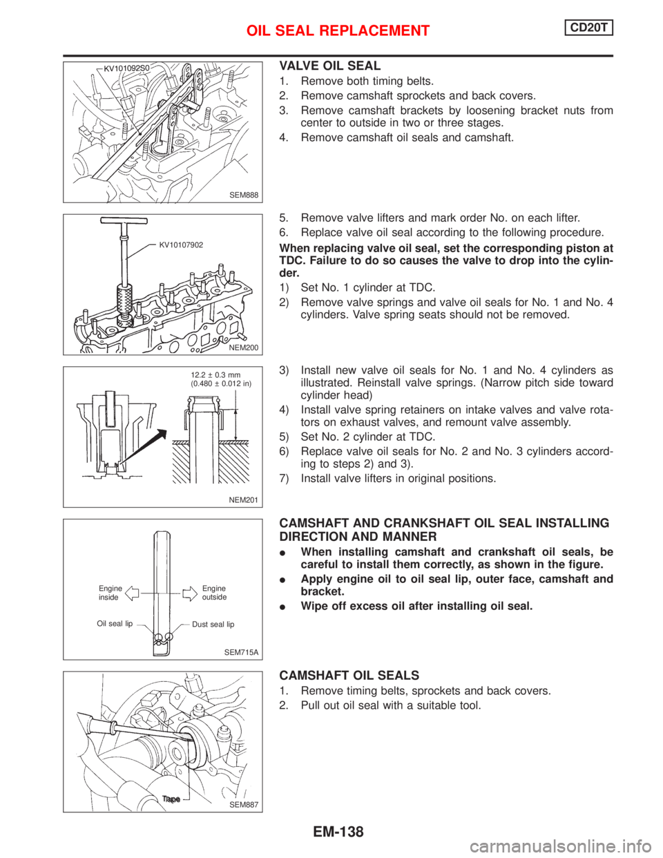
VALVE OIL SEAL
1. Remove both timing belts.
2. Remove camshaft sprockets and back covers.
3. Remove camshaft brackets by loosening bracket nuts from
center to outside in two or three stages.
4. Remove camshaft oil seals and camshaft.
5. Remove valve lifters and mark order No. on each lifter.
6. Replace valve oil seal according to the following procedure.
When replacing valve oil seal, set the corresponding piston at
TDC. Failure to do so causes the valve to drop into the cylin-
der.
1) Set No. 1 cylinder at TDC.
2) Remove valve springs and valve oil seals for No. 1 and No. 4
cylinders. Valve spring seats should not be removed.
3) Install new valve oil seals for No. 1 and No. 4 cylinders as
illustrated. Reinstall valve springs. (Narrow pitch side toward
cylinder head)
4) Install valve spring retainers on intake valves and valve rota-
tors on exhaust valves, and remount valve assembly.
5) Set No. 2 cylinder at TDC.
6) Replace valve oil seals for No. 2 and No. 3 cylinders accord-
ing to steps 2) and 3).
7) Install valve lifters in original positions.
CAMSHAFT AND CRANKSHAFT OIL SEAL INSTALLING
DIRECTION AND MANNER
IWhen installing camshaft and crankshaft oil seals, be
careful to install them correctly, as shown in the figure.
IApply engine oil to oil seal lip, outer face, camshaft and
bracket.
IWipe off excess oil after installing oil seal.
CAMSHAFT OIL SEALS
1. Remove timing belts, sprockets and back covers.
2. Pull out oil seal with a suitable tool.
SEM888
NEM200 KV10107902
NEM201 12.2 0.3 mm
(0.480 0.012 in)
SEM715A Engine
inside
Oil seal lipEngine
outside
Dust seal lip
.SEM887 Tape
OIL SEAL REPLACEMENTCD20T
EM-138
Page 1703 of 2267
WARNING:
ISituate vehicle on a flat and solid surface.
IPlace chocks at front and back of rear wheels.
IDo not remove engine until exhaust system has com-
pletely cooled down.
IFor safety during subsequent steps, the tension of wires
should be slackened against the engine.
IBefore removing front axle from transaxle, place safety
stands under designated front supporting points. Refer to
GI section for lifting points and towing.
IBe sure to hoist engine and transaxle in a safe manner.
IFor engines not equipped with engine slingers, attach
proper slingers and bolts described in PARTS CATALOG
or Eurofast.
CAUTION:
IWhen lifting engine, be careful not to strike adjacent parts,
especially accelerator wire casing, brake lines, and brake
master cylinder.
IAlways use engine slingers when hoisting the engine.
IWhen removing drive shaft, be careful not to damage tran-
saxle oil seal.
1. Remove engine undercovers and splash covers.
2. Remove front exhaust tube.
3. Disconnect lower water hose from radiator and drain coolant.
4. Drain transaxle oil.
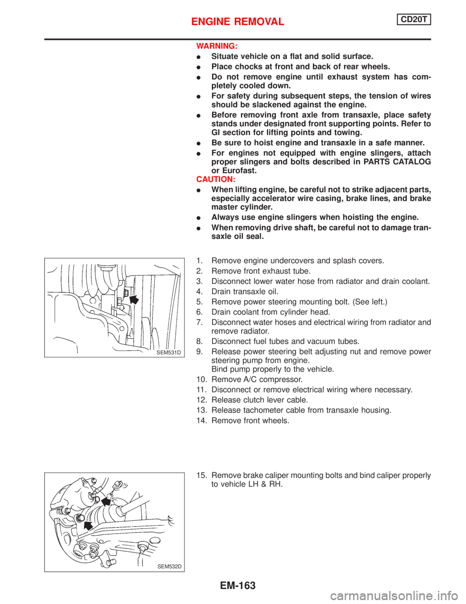
5. Remove power steering mounting bolt. (See left.)
6. Drain coolant from cylinder head.
7. Disconnect water hoses and electrical wiring from radiator and
remove radiator.
8. Disconnect fuel tubes and vacuum tubes.
9. Release power steering belt adjusting nut and remove power
steering pump from engine.
Bind pump properly to the vehicle.
10. Remove A/C compressor.
11. Disconnect or remove electrical wiring where necessary.
12. Release clutch lever cable.
13. Release tachometer cable from transaxle housing.
14. Remove front wheels.
15. Remove brake caliper mounting bolts and bind caliper properly
to vehicle LH & RH.
.SEM531D
SEM532D
ENGINE REMOVALCD20T
EM-163
Page 1715 of 2267
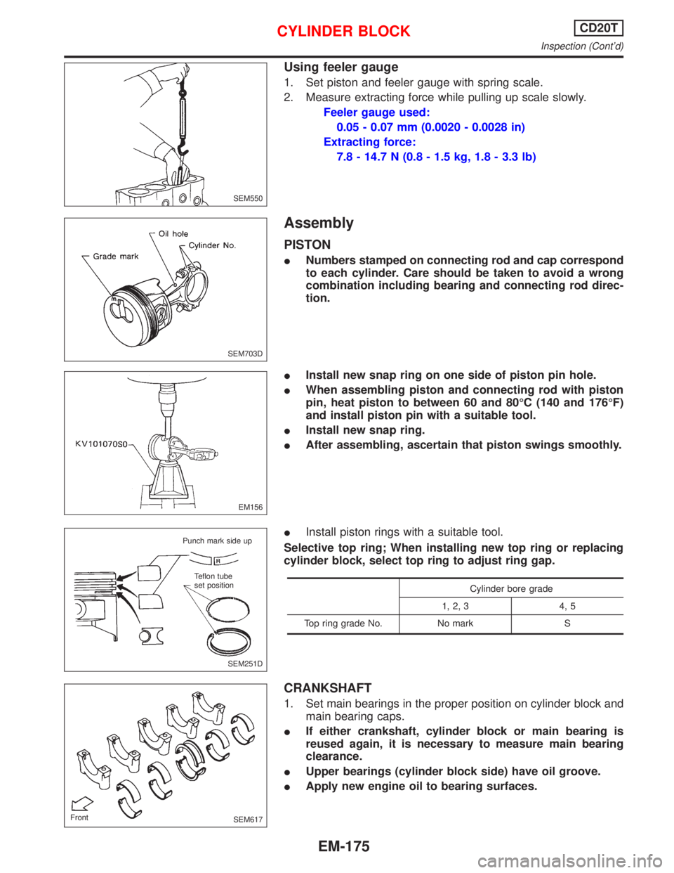
Using feeler gauge
1. Set piston and feeler gauge with spring scale.
2. Measure extracting force while pulling up scale slowly.
Feeler gauge used:
0.05 - 0.07 mm (0.0020 - 0.0028 in)
Extracting force:
7.8 - 14.7 N (0.8 - 1.5 kg, 1.8 - 3.3 lb)
Assembly
PISTON
INumbers stamped on connecting rod and cap correspond
to each cylinder. Care should be taken to avoid a wrong
combination including bearing and connecting rod direc-
tion.
IInstall new snap ring on one side of piston pin hole.
IWhen assembling piston and connecting rod with piston
pin, heat piston to between 60 and 80ÉC (140 and 176ÉF)
and install piston pin with a suitable tool.
IInstall new snap ring.
IAfter assembling, ascertain that piston swings smoothly.
IInstall piston rings with a suitable tool.
Selective top ring; When installing new top ring or replacing
cylinder block, select top ring to adjust ring gap.
Cylinder bore grade
1, 2, 3 4, 5
Top ring grade No. No mark S
CRANKSHAFT
1. Set main bearings in the proper position on cylinder block and
main bearing caps.
IIf either crankshaft, cylinder block or main bearing is
reused again, it is necessary to measure main bearing
clearance.
IUpper bearings (cylinder block side) have oil groove.
IApply new engine oil to bearing surfaces.
SEM550
SEM703D
EM156
SEM251D Punch mark side up
Teflon tube
set position
SEM617 Front
CYLINDER BLOCKCD20T
Inspection (Cont'd)
EM-175
Page 1717 of 2267
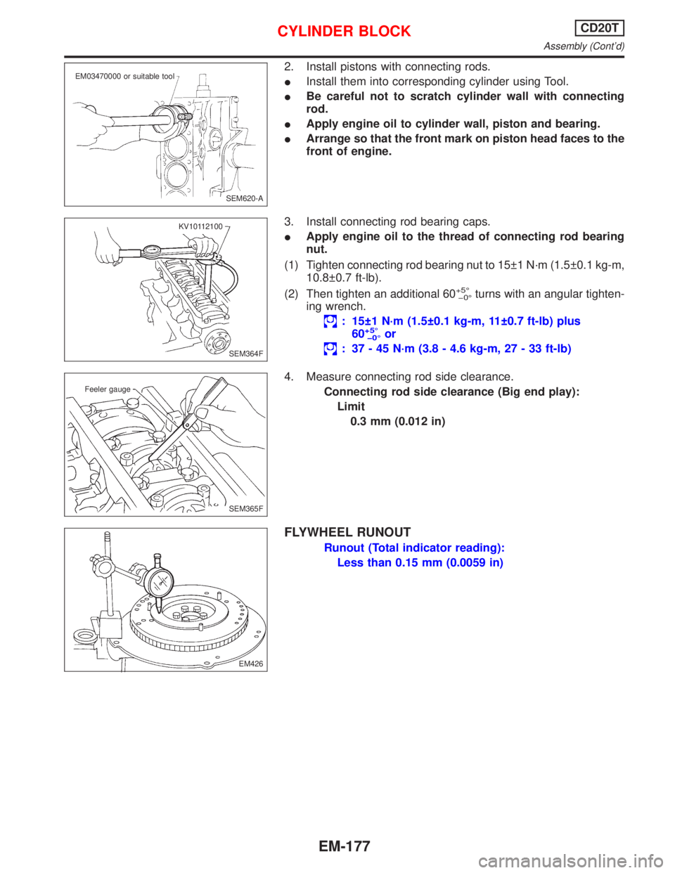
2. Install pistons with connecting rods.
IInstall them into corresponding cylinder using Tool.
IBe careful not to scratch cylinder wall with connecting
rod.
IApply engine oil to cylinder wall, piston and bearing.
IArrange so that the front mark on piston head faces to the
front of engine.
3. Install connecting rod bearing caps.
IApply engine oil to the thread of connecting rod bearing
nut.
(1) Tighten connecting rod bearing nut to 15 1 N´m (1.5 0.1 kg-m,
10.8 0.7 ft-lb).
(2) Then tighten an additional 60
+5É
þ0Éturns with an angular tighten-
ing wrench.
: 15 1 N´m (1.5 0.1 kg-m, 11 0.7 ft-lb) plus
60+5É
þ0Éor
: 37 - 45 N´m (3.8 - 4.6 kg-m, 27 - 33 ft-lb)
4. Measure connecting rod side clearance.
Connecting rod side clearance (Big end play):
Limit
0.3 mm (0.012 in)
FLYWHEEL RUNOUT
Runout (Total indicator reading):
Less than 0.15 mm (0.0059 in)
SEM620-A EM03470000 or suitable tool
SEM364F KV10112100
SEM365F Feeler gauge
EM426
CYLINDER BLOCKCD20T
Assembly (Cont'd)
EM-177
Page 1799 of 2267
Regarding the procedures of NATS initialisation and NATS igni-
tion key ID registration, refer to CONSULT-II operation manual
for NATS.
Therefore, CONSULT-II NATS software (program card and
operation manual) must be kept strictly confidential to main-
tain the integrity of the anti-theft function.
lWhen servicing NATS (trouble diagnoses, system initialisa-
tion and additional registration of other NATS ignition key
IDs), it may be necessary to re-register original key identifi-
cation. Therefore, be sure to obtain all keys from vehicle
owner.
A maximum of four key IDs can be registered into NATS.
Precautions for Super Lock System
Locking the driver's door or front passenger's door with the key
or remote control will lock all doors and activate the Super Lock
System.
The Super Lock System is designed to prevent theft as it can
only be released when a front door is unlocked using a key or
remote control.
This means, none of the door locks can be operated from the
inside using the door lock knob when the Super Lock System is
activated.
General Precautions
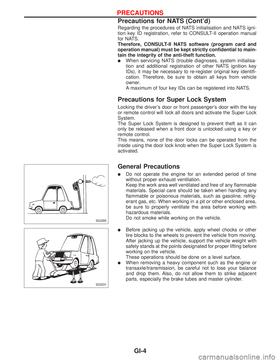
lDo not operate the engine for an extended period of time
without proper exhaust ventilation.
Keep the work area well ventilated and free of any flammable
materials. Special care should be taken when handling any
flammable or poisonous materials, such as gasoline, refrig-
erant gas, etc. When working in a pit or other enclosed area,
be sure to properly ventilate the area before working with
hazardous materials.
Do not smoke while working on the vehicle.
lBefore jacking up the vehicle, apply wheel chocks or other
tire blocks to the wheels to prevent the vehicle from moving.
After jacking up the vehicle, support the vehicle weight with
safety stands at the points designated for proper lifting before
working on the vehicle.
These operations should be done on a level surface.
lWhen removing a heavy component such as the engine or
transaxle/transmission, be careful not to lose your balance
and drop them. Also, do not allow them to strike adjacent
parts, especially the brake tubes and master cylinder.
SGI285
SGI231
PRECAUTIONS
Precautions for NATS (Cont'd)
GI-4
Page 1809 of 2267
Number Item Description
p19Current flow arrow
lArrow indicates electric current flow, especially where the direction of stan-
dard flow (vertically downward or horizontally from left to right) is difficult to
follow.
lA double arrow ªFÐ
Eº shows that current can flow in either direction depend-
ing on circuit operation.
p20System branchlThis shows that the system branches to another system identified by cell
code (section and system).
p21Page crossing
lThis arrow shows that the circuit continues to another page identified by cell
code.
lThe C will match with the C on another page within the system other than the
next or preceding pages.
p22Shielded linelThe line enclosed by broken line circle shows shield wire.
p23Component box in wave
linelThis shows that another part of the component is also shown on another
page (indicated by wave line) within the system.
p24Component namelThis shows the name of a component.
p25Connector number
lThis shows the connector number.
lThe letter shows which harness the connector is located in.
Example:M: main harness. For details and to locate the connector, refer to
EL section (ªMain Harnessº, ªHARNESS LAYOUTº). A coordinate grid is
included for complex harnesses to aid in locating connectors.
p26Ground (GND)lThe line spliced and grounded under wire color shows that ground line is
spliced at the grounded connector.
p27Ground (GND)lThis shows the ground connection.
p28Connector viewslThis area shows the connector faces of the components in the wiring diagram
on the page.
p29Common componentlConnectors enclosed in broken line show that these connectors belong to the
same component.
p30Connector colorlThis shows a code for the color of the connector. For code meaning, refer to
wire color codes, Number
p14of this chart.
p31Fusible link and fuse box
lThis shows the arrangement of fusible link(s) and fuse(s), used for connector
views of ªPOWER SUPPLY ROUTINGº in EL section.
The open square shows current flow in, and the shaded square shows cur-
rent flow out.
p32Reference arealThis shows that more information on the Super Multiple Junction (SMJ) and
Joint Connectors (J/C) exists on the foldout page.
HOW TO READ WIRING DIAGRAMS
Description (Cont'd)
GI-14
Page 1831 of 2267
HOW TO FOLLOW THIS FLOW CHART
Work and diagnostic procedure
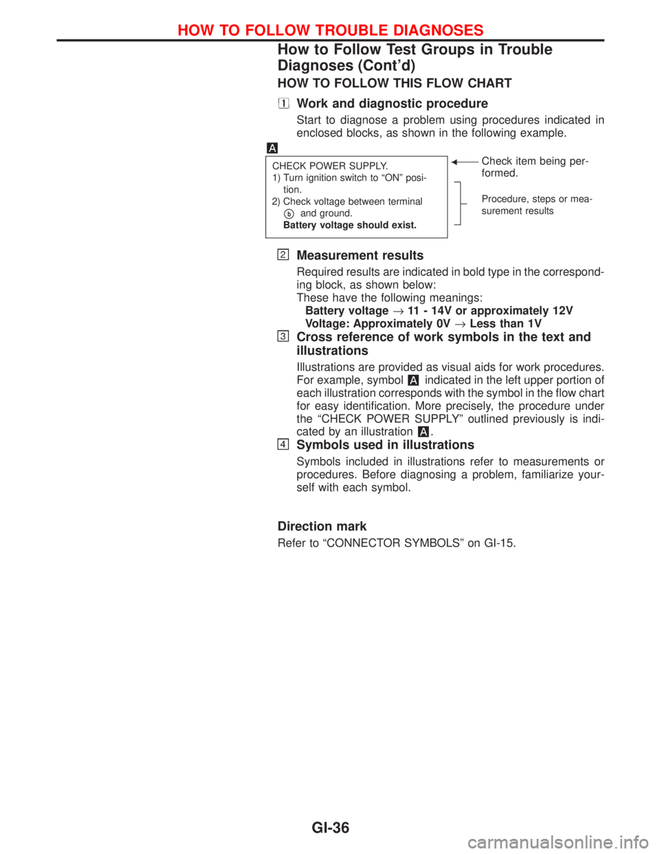
Start to diagnose a problem using procedures indicated in
enclosed blocks, as shown in the following example.
CHECK POWER SUPPLY.
1) Turn ignition switch to ªONº posi-
tion.
2) Check voltage between terminal
pband ground.
Battery voltage should exist.
FCheck item being per-
formed.
Procedure, steps or mea-
surement results
Measurement results
Required results are indicated in bold type in the correspond-
ing block, as shown below:
These have the following meanings:
Battery voltage®11 - 14V or approximately 12V
Voltage: Approximately 0V®Less than 1V
Cross reference of work symbols in the text and
illustrations
Illustrations are provided as visual aids for work procedures.
For example, symbol
indicated in the left upper portion of
each illustration corresponds with the symbol in the flow chart
for easy identification. More precisely, the procedure under
the ªCHECK POWER SUPPLYº outlined previously is indi-
cated by an illustration
.
Symbols used in illustrations
Symbols included in illustrations refer to measurements or
procedures. Before diagnosing a problem, familiarize your-
self with each symbol.
Direction mark
Refer to ªCONNECTOR SYMBOLSº on GI-15.
HOW TO FOLLOW TROUBLE DIAGNOSES
How to Follow Test Groups in Trouble
Diagnoses (Cont'd)
GI-36
Page 1864 of 2267
DESCRIPTION
General
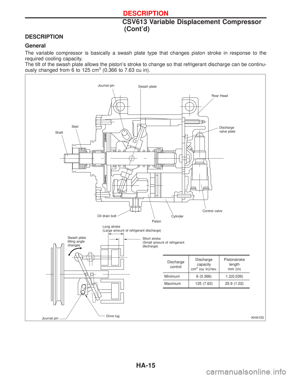
The variable compressor is basically a swash plate type that changes piston stroke in response to the
required cooling capacity.
The tilt of the swash plate allows the piston's stroke to change so that refrigerant discharge can be continu-
ously changed from 6 to 125 cm
3(0.366 to 7.63 cu in).
KHA103 ShaftSealJournal pin
Swash plate
Rear Head
Discharge
valve plate
Control valve
Cylinder
Piston Oil drain bolt
Swash plate
tilting angle
changesLong stroke
(Large amount of refrigerant discharge)
Short stroke
(Small amount of refrigerant
discharge)
Drive lug
Journal pin
Discharge
controlDischarge
capacity
cm
3(cu in)/rev.Pistonstroke
length
mm (in)
Minimum 6 (0.366) 1.2(0.039)
Maximum 125 (7.63) 25.9 (1.02)
DESCRIPTION
CSV613 Variable Displacement Compressor
(Cont'd)
HA-15