Page 1865 of 2267
Operation
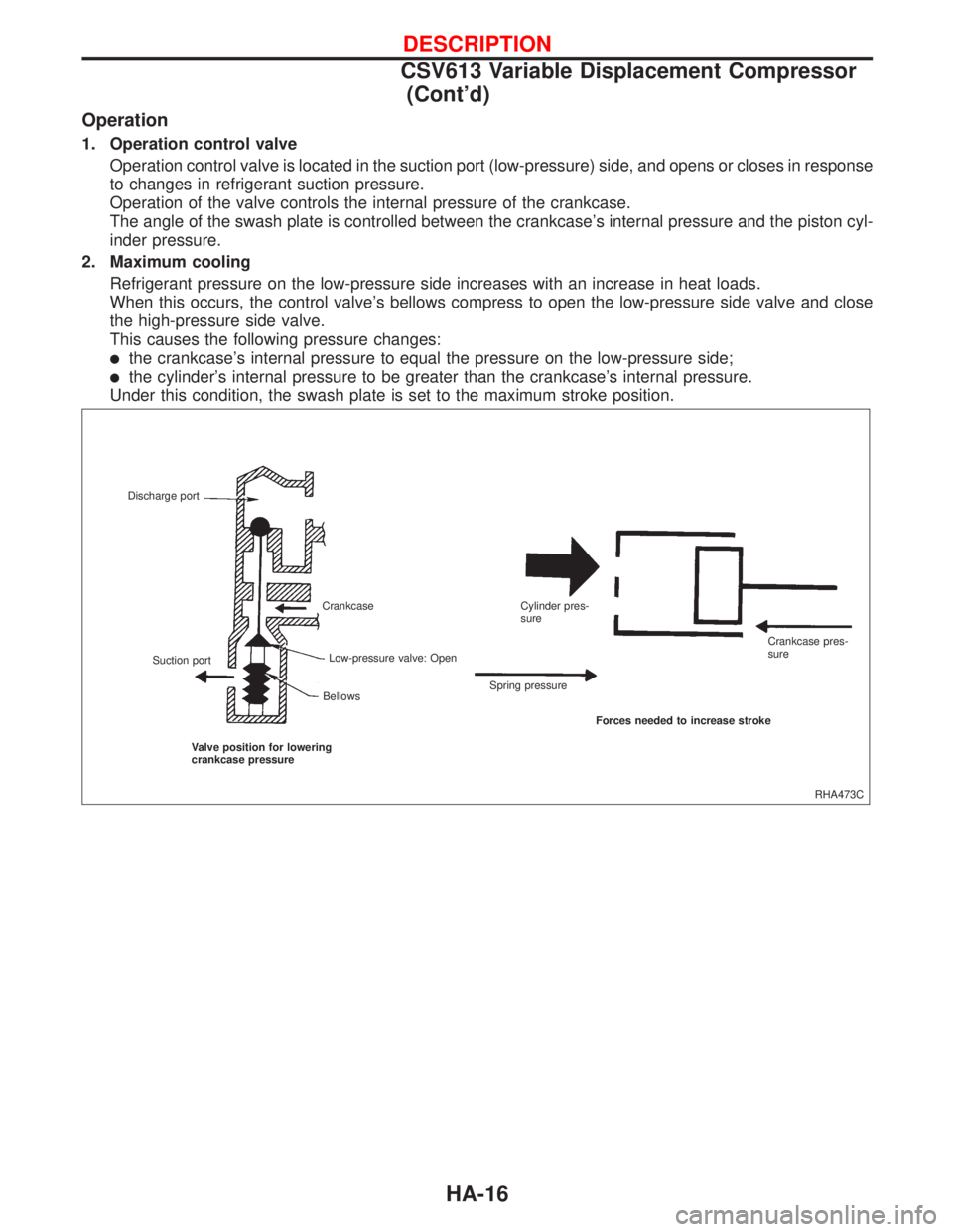
1. Operation control valve
Operation control valve is located in the suction port (low-pressure) side, and opens or closes in response
to changes in refrigerant suction pressure.
Operation of the valve controls the internal pressure of the crankcase.
The angle of the swash plate is controlled between the crankcase's internal pressure and the piston cyl-
inder pressure.
2. Maximum cooling
Refrigerant pressure on the low-pressure side increases with an increase in heat loads.
When this occurs, the control valve's bellows compress to open the low-pressure side valve and close
the high-pressure side valve.
This causes the following pressure changes:
lthe crankcase's internal pressure to equal the pressure on the low-pressure side;
lthe cylinder's internal pressure to be greater than the crankcase's internal pressure.
Under this condition, the swash plate is set to the maximum stroke position.
RHA473C Discharge port
Suction portCrankcase
Low-pressure valve: Open
Bellows
Valve position for lowering
crankcase pressureSpring pressureCylinder pres-
sure
Crankcase pres-
sure
Forces needed to increase stroke
DESCRIPTION
CSV613 Variable Displacement Compressor
(Cont'd)
HA-16
Page 1866 of 2267
3. Capacity control
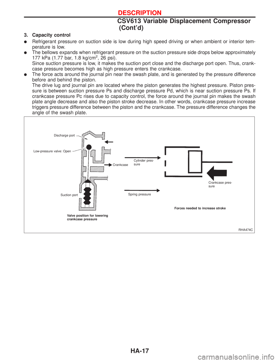
lRefrigerant pressure on suction side is low during high speed driving or when ambient or interior tem-
perature is low.
lThe bellows expands when refrigerant pressure on the suction pressure side drops below approximately
177 kPa (1.77 bar, 1.8 kg/cm2, 26 psi).
Since suction pressure is low, it makes the suction port close and the discharge port open. Thus, crank-
case pressure becomes high as high pressure enters the crankcase.
lThe force acts around the journal pin near the swash plate, and is generated by the pressure difference
before and behind the piston.
The drive lug and journal pin are located where the piston generates the highest pressure. Piston pres-
sure is between suction pressure Ps and discharge pressure Pd, which is near suction pressure Ps. If
crankcase pressure Pc rises due to capacity control, the force around the journal pin makes the swash
plate angle decrease and also the piston stroke decrease. In other words, crankcase pressure increase
triggers pressure difference between the piston and the crankcase. The pressure difference changes the
angle of the swash plate.
RHA474C Discharge port
Suction portCrankcase Low-pressure valve: Open
Valve position for lowering
crankcase pressureSpring pressureCylinder pres-
sure
Crankcase pres-
sure
Forces needed to increase stroke
DESCRIPTION
CSV613 Variable Displacement Compressor
(Cont'd)
HA-17
Page 1879 of 2267
Checking Resistor
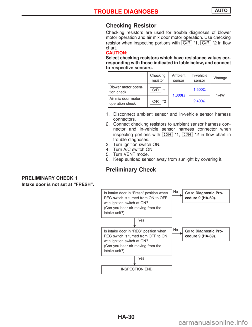
Checking resistors are used for trouble diagnoses of blower
motor operation and air mix door motor operation. Use checking
resistor when inspecting portions with C/R
*1, C/R*2 in flow
chart.
CAUTION:
Select checking resistors which have resistance values cor-
responding with those indicated in table below, and connect
to respective sensors.
Checking
resistorAmbient
sensorIn-vehicle
sensorWattage
Blower motor opera-
tion checkC/R
*1
1,000W1,500W
1/4W
Air mix door motor
operation checkC/R
*22,490W
1. Disconnect ambient sensor and in-vehicle sensor harness
connectors.
2. Connect checking resistors to ambient sensor harness con-
nector and in-vehicle sensor harness connector when
inspecting portions with C/R
*1, C/R*2 in flow chart in
trouble diagnoses.
3. Turn ignition switch ON.
4. Turn A/C switch ON.
5. Turn VENT mode.
6. Keep sunload sensor away from sunlight by covering it.
Preliminary Check
PRELIMINARY CHECK 1
Intake door is not set at ªFRESHº.
Is intake door in ªFreshº position when
REC switch is turned from ON to OFF
with ignition switch at ON?
(Can you hear air moving from the
intake unit?)
Ye s
ENo
Go toDiagnostic Pro-
cedure 9 (HA-69).
Is intake door in ªRECº position when
REC switch is turned from OFF to ON
with ignition switch at ON?
(Can you hear air moving from the
intake unit?)
Ye s
ENo
Go toDiagnostic Pro-
cedure 9 (HA-69).
INSPECTION END
H
H
TROUBLE DIAGNOSESAUTO
HA-30
Page 1882 of 2267
Performance Test Diagnoses
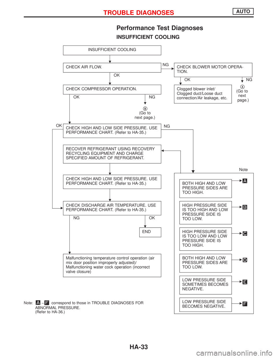
INSUFFICIENT COOLING
INSUFFICIENT COOLING
CHECK AIR FLOW.
OK
ENG
CHECK BLOWER MOTOR OPERA-
TION.
OK NG
CHECK COMPRESSOR OPERATION.
OK NGClogged blower inlet/
Clogged duct/Loose duct
connection/Air leakage, etc.
pA(Go to
next
page.)
pB(Go to
next page.)
OK
CHECK HIGH AND LOW SIDE PRESSURE. USE
PERFORMANCE CHART. (Refer to HA-35.)NG
H RECOVER REFRIGERANT USING RECOVERY
RECYCLING EQUIPMENT AND CHARGE
SPECIFIED AMOUNT OF REFRIGERANT.
F
Note
CHECK HIGH AND LOW SIDE PRESSURE. USE
PERFORMANCE CHART. (Refer to HA-35.)
BOTH HIGH AND LOW
PRESSURE SIDES ARE
TOO HIGH.E
ECHECK DISCHARGE AIR TEMPERATURE. USE
PERFORMANCE CHART. (Refer to HA-35.)
NG OKHIGH PRESSURE SIDE
IS TOO HIGH AND LOW
PRESSURE SIDE IS
TOO LOW.
E
ENDHIGH PRESSURE SIDE
IS TOO LOW AND LOW
PRESSURE SIDE IS
TOO HIGH.E
Malfunctioning temperature control operation (air
mix door position improperly adjusted)/
Malfunctioning water cock operation (incorrect
valve closure)BOTH HIGH AND LOW
PRESSURE SIDES ARE
TOO LOW.E
LOW PRESSURE SIDE
SOMETIMES BECOMES
NEGATIVE.E
LOW PRESSURE SIDE
BECOMES NEGATIVE.ENote:þcorrespond to those in TROUBLE DIAGNOSES FOR
ABNORMAL PRESSURE.
(Refer to HA-36.)
H
HHH
H
H
H
H
H
H
TROUBLE DIAGNOSESAUTO
HA-33
Page 1929 of 2267
PRESSURE SENSOR
THERMO CONTROL AMP.
Evaporator outlet air temperature
ÉC (ÉF)Thermo amp.
operationTester
Decreasing to 0.1 - 0.9 (32 - 34) Turn OFFApprox. 12V
Increasing to 2.5 - 3.5 (37 - 38) Turn ONApprox. 0V
Control Panel System
This control panel system operates the intake door motor to activate their corresponding doors.
SWITCHES AND THEIR CONTROL FUNCTIONS
Knob/Switch position
Air outlet Intake airCom-
pressor
Knob/Switch A/C
A/CqON*1
Mode
qVENT
qB/L
qFOOT
qF/D
qDEF FRE ON*1
qREC
*1: Compressor is operated by thermo control amp. (With diesel engine)
Compressor is operated by ECM (with SR engine and QG engine).
KHA121 Dual-pressure switch
GND
V out
VccV out (V)
(3.882)
(0.362)Vcc = 5.0 (VDC)
0.278 (1.8) 2.65 (26)Pg
Kpa
(kgf/cm
2G)
RHA329F
TROUBLE DIAGNOSESAUTO
Electrical Components Inspection (Cont'd)
HA-80
Page 2093 of 2267
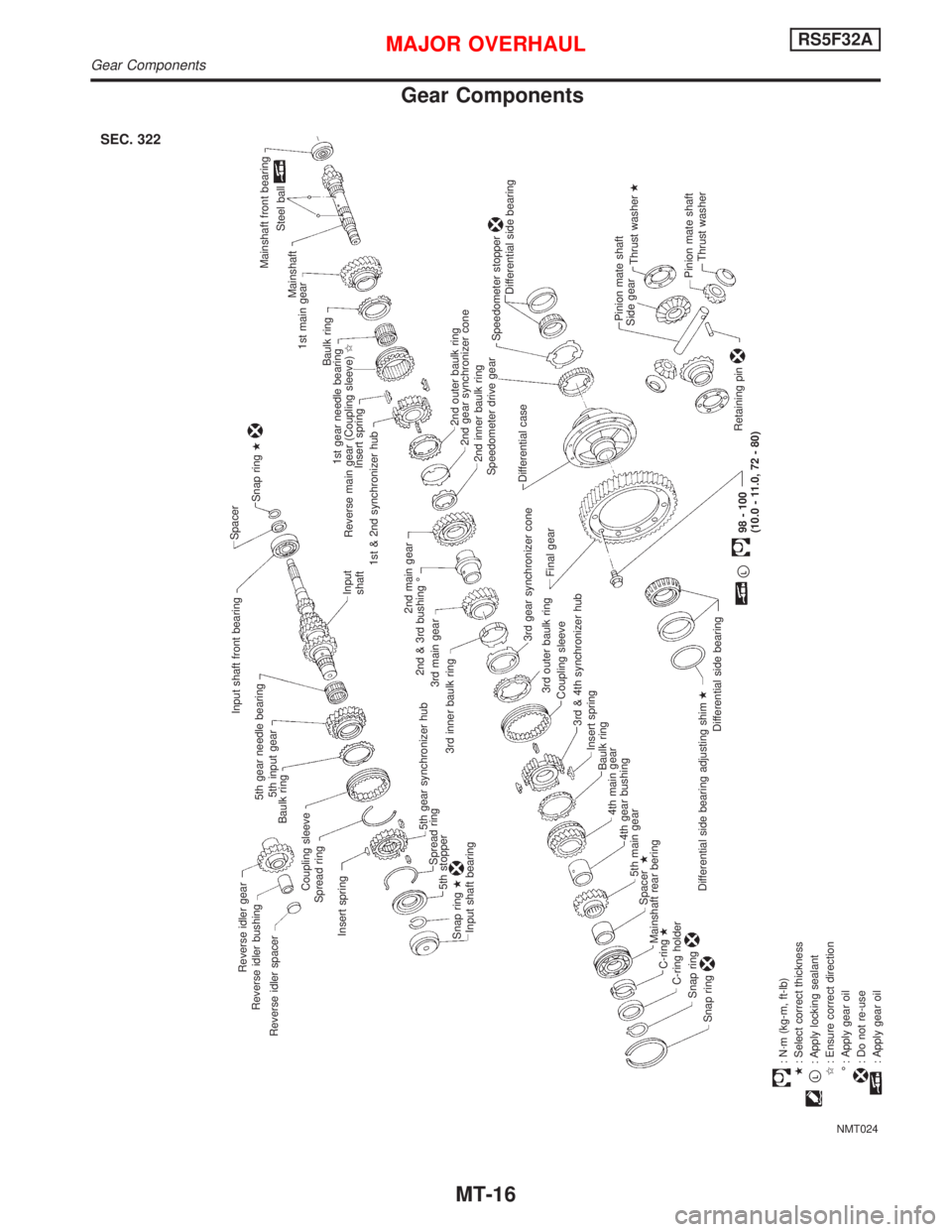
Gear Components
NMT024
.
Reverse idler gear
Reverse idler bushing
Reverse idler spacerInput shaft front bearing
5th gear needle bearing
5th input gear
Baulk ring
Spread ring
Insert springCoupling sleeveSpacer
Snap ringH
Input
shaft
5th gear synchronizer hub
Spread ring
5th stopper
Snap ringH
Input shaft bearing.
Mainshaft front bearing
Steel ball
Mainshaft
1st main gear
Baulk ring
1st gear needle bearing
Reverse main gear (Coupling sleeve)I
Insert spring
1st & 2nd synchronizer hub
2nd main gear
2nd & 3rd bushing É
3rd main gear
3rd inner baulk ring
2nd outer baulk ring
2nd gear synchronizer cone
2nd inner baulk ring
3rd gear synchronizer cone
.3rd outer baulk ring
Coupling sleeve
3rd & 4th synchronizer hub
Insert spring
Baulk ring
4th main gear
4th gear bushing
5th main gear
SpacerH
Mainshaft rear bering
C-ringH
C-ring holder
Snap ring
Snap ring
Differential side bearing Speedometer stopper
.
Speedometer drive gear
pL
98 - 100
(10.0 - 11.0, 72 - 80) Differential side bearing adjusting shimH
Differential side bearingFinal gearDifferential case
Pinion mate shaft
.
Side gear
Thrust washerH
Pinion mate shaft
Thrust washer
Retaining pin
: N´m (kg-m, ft-lb)
H: Select correct thickness
pL: Apply locking sealant
I: Ensure correct direction
É : Apply gear oil: Do not re-use: Apply gear oil
SEC. 322
MAJOR OVERHAULRS5F32A
Gear Components
MT-16
Page 2210 of 2267
DISPOSING OF AIR BAG MODULE AND SEAT BELT
PRE-TENSIONER
Deployed air bag modules and seat belt pre-tensioners are very
hot. Before disposing of air bag module, and seat belt pre-
tensioner, wait at least 30 minutes, and 10 minutes, respectively.
Seal them in a plastic bag before disposal.
CAUTION:
lNever apply water to a deployed air bag module and seat
belt pre-tensioner.
lBe sure to wear gloves when handling a deployed air
bag module and seat belt pre-tensioner.
lNo poisonous gas is produced upon air bag module
deployment. However, be careful not to inhale gas since
it irritates throat and can cause choking.
lDo not attempt to disassemble air bag module and seat
belt pre-tensioner.
lAir bag module and seat belt pre-tensioner cannot be
re-used.
lWash your hands clean after finishing work.
SBF276H
SUPPLEMENTAL RESTRAINT SYSTEM (SRS)
Disposal of Air Bag Module and Seat Belt
Pre-tensioner (Cont'd)
RS-27
Page 2222 of 2267
![NISSAN PRIMERA 1999 Electronic Repair Manual If no malfunction is detected on ªSELF-DIAG [CURRENT]º but
malfunction is indicated by the ªAIR BAGº, warning lamp, go to
DIAGNOSTIC PROCEDURE 4, page RS-43, to diagnose the
following situations:
NISSAN PRIMERA 1999 Electronic Repair Manual If no malfunction is detected on ªSELF-DIAG [CURRENT]º but
malfunction is indicated by the ªAIR BAGº, warning lamp, go to
DIAGNOSTIC PROCEDURE 4, page RS-43, to diagnose the
following situations:](/manual-img/5/57377/w960_57377-2221.png)
If no malfunction is detected on ªSELF-DIAG [CURRENT]º but
malfunction is indicated by the ªAIR BAGº, warning lamp, go to
DIAGNOSTIC PROCEDURE 4, page RS-43, to diagnose the
following situations:
lSelf-diagnostic result ªSELF-DIAG [PAST]º (previously
stored in the memory) might not be erased after repair.
lThe SRS system malfunctions intermittently.
8. Touch ªPRINTº.
9. Compare diagnostic codes to ªCONSULT-II Diagnostic Code
Chartº, page RS-39.
10. Touch ªBACKº key of CONSULT-II until ªSELECT SYSTEM º
appears in order to return to User mode from Diagnosis
mode.
11. Turn ignition switch ªOFFº, then turn off and disconnect CON-
SULT-II and both battery cables.
12. Repair the system as outlined by the ªRepair orderº in ªCON-
SULT-II Diagnostic Code Chartº, that corresponds to the self-
diagnostic result. For replacement procedure of component
parts, refer to RS-13.
13. After repairing the system, go to DIAGNOSTIC PROCE-
DURE 3, page RS-42 for final checking.
CONSULT-II Diagnostic Code Chart
(ªSELF-DIAGNOSISº)
Diagnostic item ExplanationRepair order
Recheck SRS at each
replacement.
NO DTC IS DETECTED. When malfunction is indi-
cated by the ªAIR BAGº
warning lamp in User mode
lLow battery voltage (Less
than 9V).lGo to DIAGNOSTIC PRO-
CEDURE 3 (RS-42) after
charging battery.
lSelf-diagnostic result
ªSELF-DIAG [PAST]º (pre-
viously stored in the
memory) might not be
erased after repair.
lIntermittent malfunction has
been detected in the past.Go to DIAGNOSTIC PROCE-
DURE 4 (RS-43).
No malfunction is detected.
lGo to DIAGNOSTIC PRO-
CEDURE 3 (RS-42).
AIRBAG MODULE
[OPEN]
lDriver's air bag module circuit is open. (including the spiral
cable)1. Visually check the wiring
harness connection.
2. Replace the harness if it
has visible damage.
3. Replace driver's air bag
module.
(Before disposing of it, it
must be deployed.)
4. Replace the spiral cable.
5. Replace the diagnosis
sensor unit.
6. Replace the related har-
ness.
C2SDC02
TROUBLE DIAGNOSES Ð Supplemental Restraint System (SRS)
Trouble Diagnoses with CONSULT-II
(Cont'd)
RS-39