Page 372 of 2267
Electric Governor
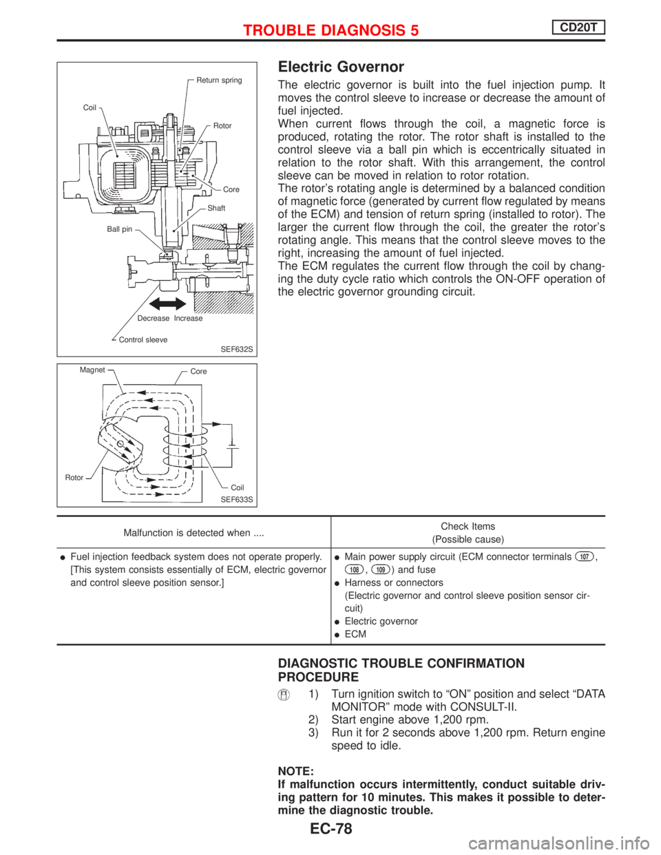
The electric governor is built into the fuel injection pump. It
moves the control sleeve to increase or decrease the amount of
fuel injected.
When current flows through the coil, a magnetic force is
produced, rotating the rotor. The rotor shaft is installed to the
control sleeve via a ball pin which is eccentrically situated in
relation to the rotor shaft. With this arrangement, the control
sleeve can be moved in relation to rotor rotation.
The rotor's rotating angle is determined by a balanced condition
of magnetic force (generated by current flow regulated by means
of the ECM) and tension of return spring (installed to rotor). The
larger the current flow through the coil, the greater the rotor's
rotating angle. This means that the control sleeve moves to the
right, increasing the amount of fuel injected.
The ECM regulates the current flow through the coil by chang-
ing the duty cycle ratio which controls the ON-OFF operation of
the electric governor grounding circuit.
Malfunction is detected when ....Check Items
(Possible cause)
lFuel injection feedback system does not operate properly.
[This system consists essentially of ECM, electric governor
and control sleeve position sensor.]lMain power supply circuit (ECM connector terminals107,
108,109) and fuse
lHarness or connectors
(Electric governor and control sleeve position sensor cir-
cuit)
lElectric governor
lECM
DIAGNOSTIC TROUBLE CONFIRMATION
PROCEDURE
1) Turn ignition switch to ªONº position and select ªDATA
MONITORº mode with CONSULT-II.
2) Start engine above 1,200 rpm.
3) Run it for 2 seconds above 1,200 rpm. Return engine
speed to idle.
NOTE:
If malfunction occurs intermittently, conduct suitable driv-
ing pattern for 10 minutes. This makes it possible to deter-
mine the diagnostic trouble.
SEF632S Return spring
Coil
Rotor
Core
Shaft
Ball pin
Decrease Increase
Control sleeve
SEF633S Magnet
Core
Rotor
Coil
TROUBLE DIAGNOSIS 5CD20T
EC-78
Page 378 of 2267
DIAGNOSTIC PROCEDURE
INSPECTION START
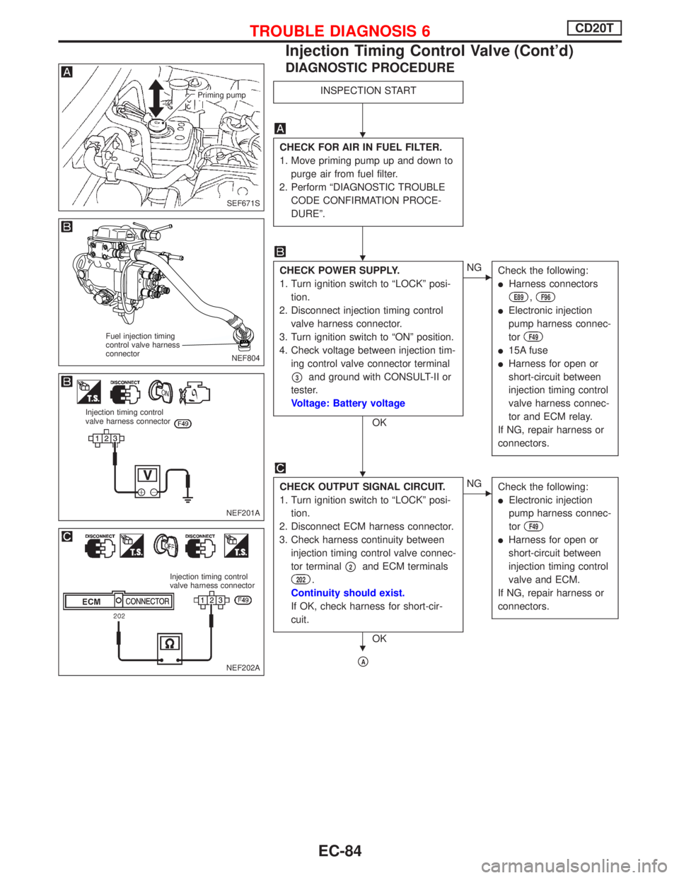
CHECK FOR AIR IN FUEL FILTER.
1. Move priming pump up and down to
purge air from fuel filter.
2. Perform ªDIAGNOSTIC TROUBLE
CODE CONFIRMATION PROCE-
DUREº.
CHECK POWER SUPPLY.
1. Turn ignition switch to ªLOCKº posi-
tion.
2. Disconnect injection timing control
valve harness connector.
3. Turn ignition switch to ªONº position.
4. Check voltage between injection tim-
ing control valve connector terminal
p3and ground with CONSULT-II or
tester.
Voltage: Battery voltage
OK
ENG
Check the following:
lHarness connectors
E89,F96
lElectronic injection
pump harness connec-
tor
F49
l15A fuse
lHarness for open or
short-circuit between
injection timing control
valve harness connec-
tor and ECM relay.
If NG, repair harness or
connectors.
CHECK OUTPUT SIGNAL CIRCUIT.
1. Turn ignition switch to ªLOCKº posi-
tion.
2. Disconnect ECM harness connector.
3. Check harness continuity between
injection timing control valve connec-
tor terminal
p2and ECM terminals
202.
Continuity should exist.
If OK, check harness for short-cir-
cuit.
OK
ENG
Check the following:
lElectronic injection
pump harness connec-
tor
F49
lHarness for open or
short-circuit between
injection timing control
valve and ECM.
If NG, repair harness or
connectors.
pA
SEF671S
Priming pump
NEF804
Fuel injection timing
control valve harness
connector
NEF201A
Injection timing control
valve harness connector
NEF202A
Injection timing control
valve harness connector
H
H
H
H
TROUBLE DIAGNOSIS 6CD20T
Injection Timing Control Valve (Cont'd)
EC-84
Page 383 of 2267
YEC805
BATTERYIGNITION SWITCH
ON or START
FUSE
BLOCK
(J/B)Refer to EL-POWER.
: Detectable line for DTC
: Non-detectable line for DTC
COOLING
FA N
RELAY-3COOLING
FA N
RELAY-2COOLING
FA N
RELAY-1
COOLING
FA N
MOTOR-1
LOWHIGHTRIPLE-
PRESSURE
SWITCHCOOLING
FA N
MOTOR-2
ECM
REFER TO THE FOLLOWING
FUSE BLOCK - Junction Box (J/B)
TROUBLE DIAGNOSIS 8CD20T
Cooling Fan (Overheat) (Cont'd)
EC-89
Page 385 of 2267
PROCEDURE A
INSPECTION START
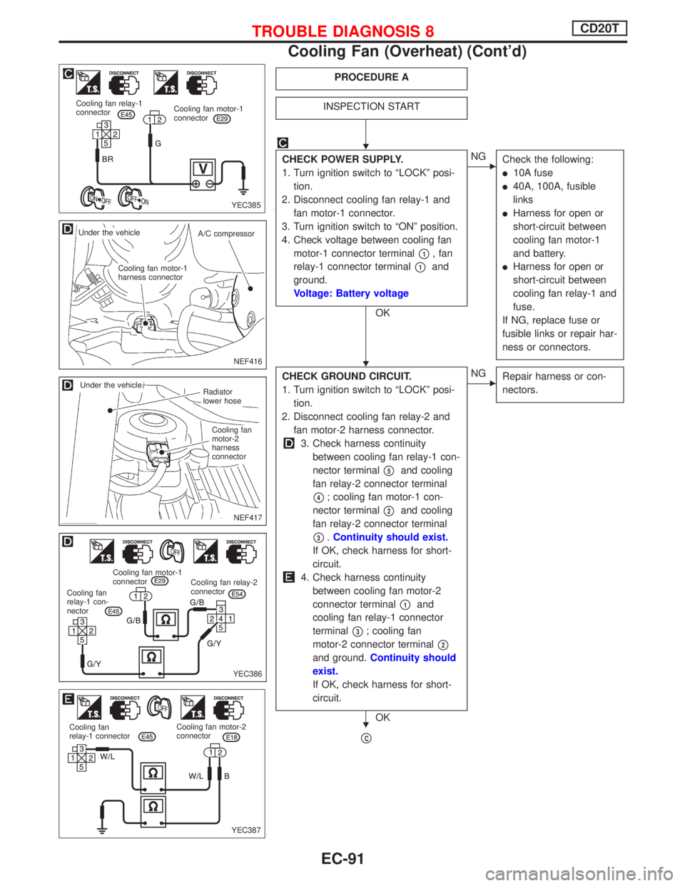
CHECK POWER SUPPLY.
1. Turn ignition switch to ªLOCKº posi-
tion.
2. Disconnect cooling fan relay-1 and
fan motor-1 connector.
3. Turn ignition switch to ªONº position.
4. Check voltage between cooling fan
motor-1 connector terminal
p1, fan
relay-1 connector terminal
p1and
ground.
Voltage: Battery voltage
OK
ENG
Check the following:
l10A fuse
l40A, 100A, fusible
links
lHarness for open or
short-circuit between
cooling fan motor-1
and battery.
lHarness for open or
short-circuit between
cooling fan relay-1 and
fuse.
If NG, replace fuse or
fusible links or repair har-
ness or connectors.
CHECK GROUND CIRCUIT.
1. Turn ignition switch to ªLOCKº posi-
tion.
2. Disconnect cooling fan relay-2 and
fan motor-2 harness connector.
3. Check harness continuity
between cooling fan relay-1 con-
nector terminal
p5and cooling
fan relay-2 connector terminal
p4; cooling fan motor-1 con-
nector terminal
p2and cooling
fan relay-2 connector terminal
p3.Continuity should exist.
If OK, check harness for short-
circuit.
4. Check harness continuity
between cooling fan motor-2
connector terminal
p1and
cooling fan relay-1 connector
terminal
p3; cooling fan
motor-2 connector terminal
p2
and ground.Continuity should
exist.
If OK, check harness for short-
circuit.
OK
ENG
Repair harness or con-
nectors.
pC
YEC385 Cooling fan relay-1
connectorCooling fan motor-1
connector
NEF416
.Under the vehicle
A/C compressor
.Cooling fan motor-1
harness connector
NEF417
.Radiator
lower hose
.Cooling fan
motor-2
harness
connector
.Under the vehicle
YEC386
Cooling fan relay-2
connector Cooling fan motor-1
connector
Cooling fan
relay-1 con-
nector
YEC387 Cooling fan
relay-1 connectorCooling fan motor-2
connector
H
H
H
TROUBLE DIAGNOSIS 8CD20T
Cooling Fan (Overheat) (Cont'd)
EC-91
Page 386 of 2267
pC
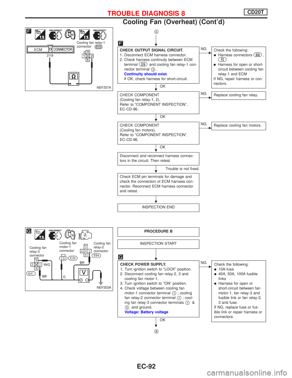
CHECK OUTPUT SIGNAL CIRCUIT.
1. Disconnect ECM harness connector.
2. Check harness continuity between ECM
terminal
219and cooling fan relay-1 con-
nector terminal
p2.
Continuity should exist.
If OK, check harness for short-circuit.
OK
ENG
Check the following:
lHarness connectorsE43,F2
lHarness for open or short-
circuit between cooling fan
relay-1 and ECM
If NG, repair harness or con-
nectors.
CHECK COMPONENT
(Cooling fan relay-1, 2).
Refer to ªCOMPONENT INSPECTIONº,
EC-CD-96.
OK
ENG
Replace cooling fan relay.
CHECK COMPONENT
(Cooling fan motors).
Refer to ªCOMPONENT INSPECTIONº,
EC-CD-96.
OK
ENG
Replace cooling fan motors.
Disconnect and reconnect harness connec-
tors in the circuit. Then retest.
Trouble is not fixed.
Check ECM pin terminals for damage and
check the connection of ECM harness con-
nector. Reconnect ECM harness connector
and retest.
INSPECTION END
PROCEDURE B
INSPECTION START
CHECK POWER SUPPLY.
1. Turn ignition switch to ªLOCKº position.
2. Disconnect cooling fan relay-2, 3 and
cooling fan motor-1.
3. Turn ignition switch to ªONº position.
4. Check voltage between cooling fan
motor-1 connector terminal
p1; cooling
fan relay-2 connector terminal
p1; cool-
ing fan relay-3 connector terminals
p1&
p3and ground.
Voltage: Battery voltage
OK
ENG
Check the following:
l10A-fusel40A, 50A, 100A fusible
links
lHarness for open or
short-circuit between fan
motor-1, fan relay-3 and
fusible link or fan relay-2,
3 and fuse.
If NG, replace fuse or fus-
ible link or repair harness or
connectors.
pD
NEF207A
Cooling fan relay-1
connector
NEF203A
Cooling fan
relay-2
connector Cooling fan
motor-1
connector Cooling fan
relay-3
connector
H
H
H
H
H
H
H
H
TROUBLE DIAGNOSIS 8CD20T
Cooling Fan (Overheat) (Cont'd)
EC-92
Page 390 of 2267
COMPONENT INSPECTION
Cooling fan relays-1, -2, -3
Check continuity between terminalsp3andp5.
Conditions Continuity
12V direct current supply between relay
terminals
p1andp2Ye s
No current supplyNo
If NG, replace cooling fan relay.
Cooling fan relay-2
Check continuity between terminalsp3andp4.
Conditions Continuity
No current supplyYe s
12V direct current supply between relay
terminals
p1andp2No
Cooling fan motors-1 and -2
1. Disconnect cooling fan motor harness connectors.
2. Supply cooling fan motor terminals with battery voltage and
check operation.
Terminals
(!)(@)
Cooling fan motor-1 and -2
p1p2
Cooling fan motor should operate.
If NG, replace cooling fan motor.
3 5
12
3 5
1 4 2
3 5
1 4 2
YEC391
Cooling fan relay 1
Cooling fan relay 3
Cooling fan relay 2
AEC781
FUSE
Cooling fan
motor-1 & -2
TROUBLE DIAGNOSIS 8CD20T
Cooling Fan (Overheat) (Cont'd)
EC-96
Page 397 of 2267
COMPONENT INSPECTION
Fuel cut solenoid valve
1. Remove fuel cut solenoid valve.
2. Check for lifting shaft when applying 12V direct current to
terminals.
If NG, replace fuel cut solenoid valve.
SEF859S ShaftFUSE
TROUBLE DIAGNOSIS 10CD20T
Fuel Cut Solenoid Valve (Cont'd)
EC-103
Page 415 of 2267
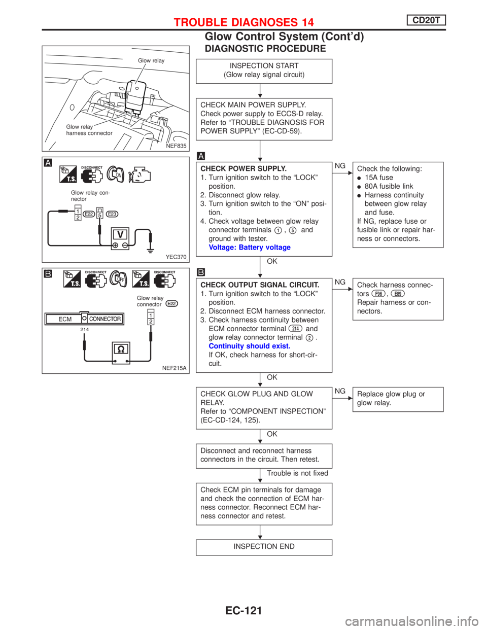
DIAGNOSTIC PROCEDURE
INSPECTION START
(Glow relay signal circuit)
CHECK MAIN POWER SUPPLY.
Check power supply to ECCS-D relay.
Refer to ªTROUBLE DIAGNOSIS FOR
POWER SUPPLYº (EC-CD-59).
CHECK POWER SUPPLY.
1. Turn ignition switch to the ªLOCKº
position.
2. Disconnect glow relay.
3. Turn ignition switch to the ªONº posi-
tion.
4. Check voltage between glow relay
connector terminals
p1,p5and
ground with tester.
Voltage: Battery voltage
OK
ENG
Check the following:
l15A fuse
l80A fusible link
lHarness continuity
between glow relay
and fuse.
If NG, replace fuse or
fusible link or repair har-
ness or connectors.
CHECK OUTPUT SIGNAL CIRCUIT.
1. Turn ignition switch to the ªLOCKº
position.
2. Disconnect ECM harness connector.
3. Check harness continuity between
ECM connector terminal
214and
glow relay connector terminal
p2.
Continuity should exist.
If OK, check harness for short-cir-
cuit.
OK
ENG
Check harness connec-
tors
F96,E89
Repair harness or con-
nectors.
CHECK GLOW PLUG AND GLOW
RELAY.
Refer to ªCOMPONENT INSPECTIONº
(EC-CD-124, 125).
OK
ENG
Replace glow plug or
glow relay.
Disconnect and reconnect harness
connectors in the circuit. Then retest.
Trouble is not fixed
Check ECM pin terminals for damage
and check the connection of ECM har-
ness connector. Reconnect ECM har-
ness connector and retest.
INSPECTION END
NEF835 Glow relay
Glow relay
harness connector
YEC370
Glow relay con-
nector
NEF215A
Glow relay
connector
H
H
H
H
H
H
H
TROUBLE DIAGNOSES 14CD20T
Glow Control System (Cont'd)
EC-121