Page 210 of 2267
lApplying brake gradually when shifting or operating clutch.
lLow friction (slippery) road.
lHigh speed concerning.
lDriving over bumps and pot holes.
lEngine speed is over 5,000 rpm with vehicle stopped.
Diagnostic Procedure 11 (ABS Warning lamp
does not come on when ignition switch is
turned ON)
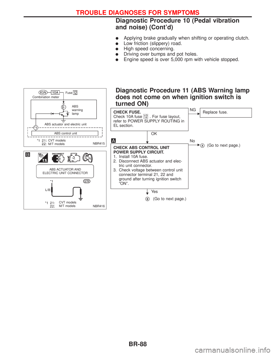
CHECK FUSE.
Check 10A fuse12. For fuse layout,
refer to POWER SUPPLY ROUTING in
EL section.
OK
ENG
Replace fuse.
CHECK ABS CONTROL UNIT
POWER SUPPLY CIRCUIT.
1. Install 10A fuse.
2. Disconnect ABS actuator and elec-
tric unit connector.
3. Check voltage between control unit
connector terminal 21, 22 and
ground after turning ignition switch
ªONº.
Ye s
ENo
pA(Go to next page.)
pB(Go to next page.)
NBR415
.Fuse
Combination meter
ABS
warning
lamp
CVT models
M/T modelsABS control unit ABS actuator and electric unit
NBR416
ABS ACTUATOR AND
ELECTRIC UNIT CONNECTOR
CVT models
M/T models
H
H
TROUBLE DIAGNOSES FOR SYMPTOMS
Diagnostic Procedure 10 (Pedal vibration
and noise) (Cont'd)
BR-88
Page 211 of 2267
pA
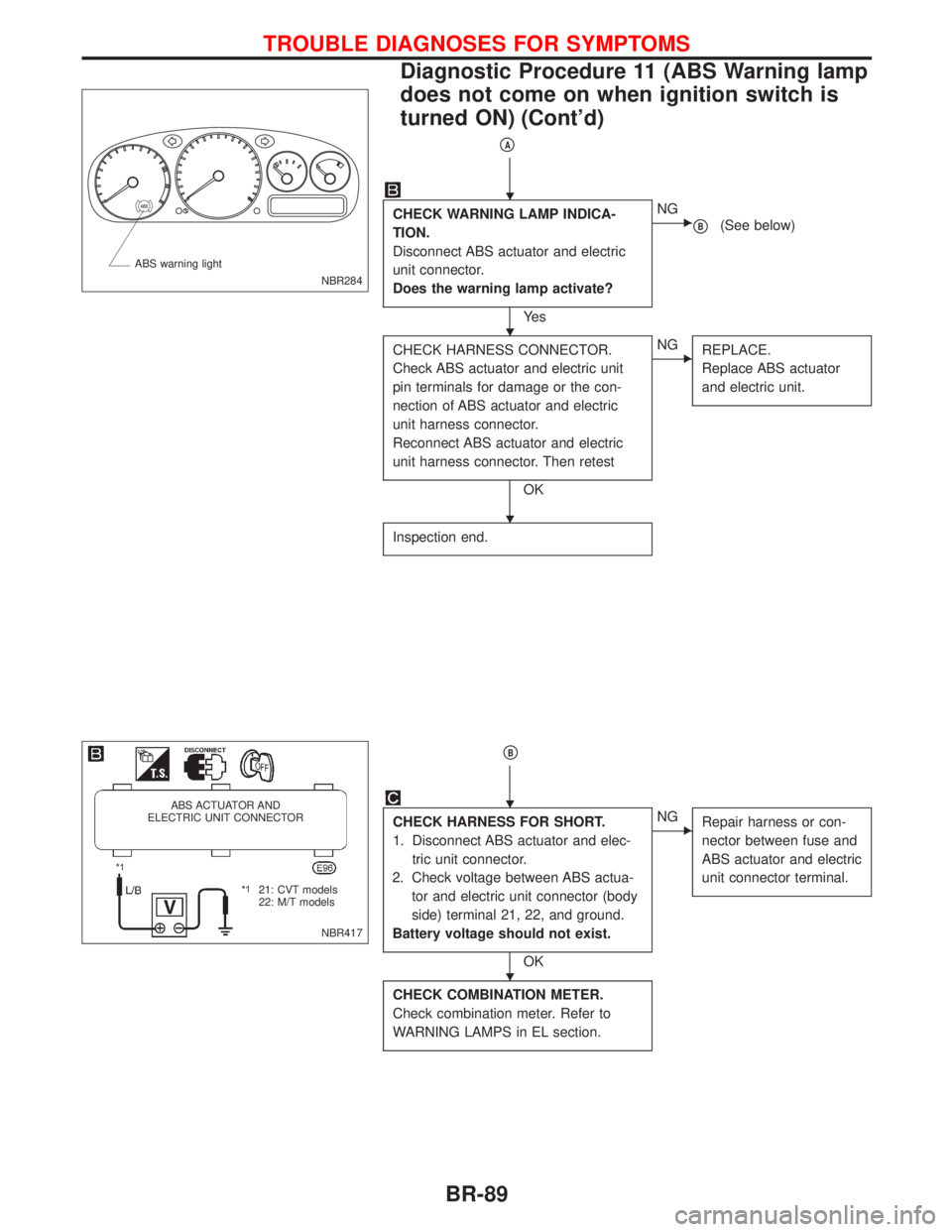
CHECK WARNING LAMP INDICA-
TION.
Disconnect ABS actuator and electric
unit connector.
Does the warning lamp activate?
Ye s
ENG
pB(See below)
CHECK HARNESS CONNECTOR.
Check ABS actuator and electric unit
pin terminals for damage or the con-
nection of ABS actuator and electric
unit harness connector.
Reconnect ABS actuator and electric
unit harness connector. Then retest
OK
ENG
REPLACE.
Replace ABS actuator
and electric unit.
Inspection end.
pB
CHECK HARNESS FOR SHORT.
1. Disconnect ABS actuator and elec-
tric unit connector.
2. Check voltage between ABS actua-
tor and electric unit connector (body
side) terminal 21, 22, and ground.
Battery voltage should not exist.
OK
ENG
Repair harness or con-
nector between fuse and
ABS actuator and electric
unit connector terminal.
CHECK COMBINATION METER.
Check combination meter. Refer to
WARNING LAMPS in EL section.
NBR284 ABS warning light
NBR417
ABS ACTUATOR AND
ELECTRIC UNIT CONNECTOR
.21: CVT models
22: M/T models
H
H
H
H
H
TROUBLE DIAGNOSES FOR SYMPTOMS
Diagnostic Procedure 11 (ABS Warning lamp
does not come on when ignition switch is
turned ON) (Cont'd)
BR-89
Page 212 of 2267
Diagnostic Procedure 12 (Warning lamp
stays on when ignition switch is turned ON)
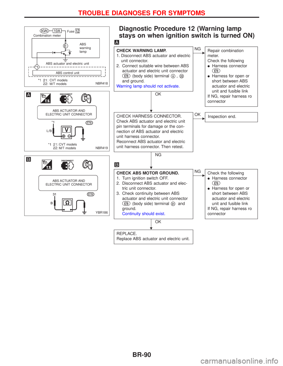
CHECK WARNING LAMP.
1. Disconnect ABS actuator and electric
unit connector.
2. Connect suitable wire between ABS
actuator and electric unit connector
E78(body side) terminalp6,p22
and ground.
Warning lamp should not activate.
OK
ENG
Repair combination
meter.
Check the following
lHarness connector
E78
lHarness for open or
short between ABS
actuator and electric
unit and fusible link
If NG, repair harness ro
connector
CHECK HARNESS CONNECTOR.
Check ABS actuator and electric unit
pin terminals for damage or the con-
nection of ABS actuator and electric
unit harness connector.
Reconnect ABS actuator and electric
unit harness connector. Then retest.
NG
EOK
Inspection end.
CHECK ABS MOTOR GROUND.
1. Turn ignition switch OFF.
2. Disconnect ABS actuator and elec-
tric unit connector.
3. Check continuity between ABS
actuator and electric unit connector
E78(body side) terminalp31and
ground.
Continuity should exist.
OK
ENG
Check the following
lHarness connector
E78
lHarness for open or
short between ABS
actuator and electric
unit and fusible link
If NG, repair harness ro
connector
REPLACE.
Replace ABS actuator and electric unit.
NBR418
.Fuse
Combination meter
ABS
warning
lamp
CVT models
M/T modelsABS control unit ABS actuator and electric unit
NBR419
ABS ACTUATOR AND
ELECTRIC UNIT CONNECTOR
CVT models
M/T models
YBR186
ABS ACTUATOR AND
ELECTRIC UNIT CONNECTOR
H
H
H
TROUBLE DIAGNOSES FOR SYMPTOMS
BR-90
Page 321 of 2267
CONSULT-II
CONSULT-II INSPECTION PROCEDURE
1. Turn off ignition switch.
2. Connect ªCONSULT-IIº to data link connector for CONSULT-
II.
(Data link connector for CONSULT-II is located behind the
fuse box cover.)
3. Turn on ignition switch.
4. Touch ªSTARTº.
5. Touch ªENGINEº.
6. Perform each diagnostic test mode according to each service
procedure.
For further information, see the CONSULT-II Operation
Manual.
NEF225A Fuse box
Data link connector
for CONSULT-II
PEF895K
PEF216U
ON BOARD DIAGNOSTIC SYSTEM DESCRIPTIONCD20T
EC-27
Page 334 of 2267
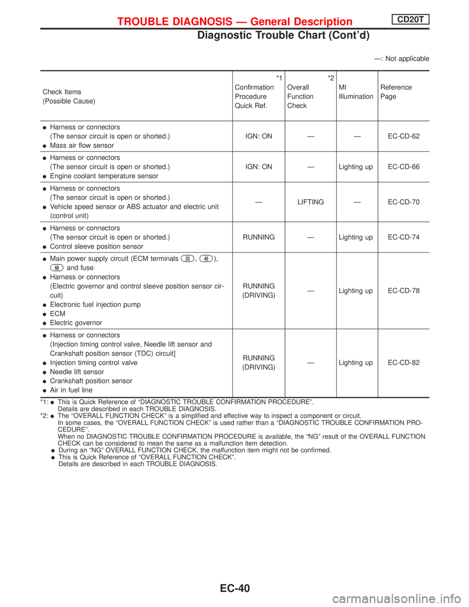
Ð: Not applicable
Check Items
(Possible Cause)*1
Confirmation
Procedure
Quick Ref.*2
Overall
Function
CheckMI
IlluminationReference
Page
lHarness or connectors
(The sensor circuit is open or shorted.)
lMass air flow sensorIGN: ON Ð Ð EC-CD-62
lHarness or connectors
(The sensor circuit is open or shorted.)
lEngine coolant temperature sensorIGN: ON Ð Lighting up EC-CD-66
lHarness or connectors
(The sensor circuit is open or shorted.)
lVehicle speed sensor or ABS actuator and electric unit
(control unit)Ð LIFTING Ð EC-CD-70
lHarness or connectors
(The sensor circuit is open or shorted.)
lControl sleeve position sensorRUNNING Ð Lighting up EC-CD-74
lMain power supply circuit (ECM terminals23,45),
68and fuse
lHarness or connectors
(Electric governor and control sleeve position sensor cir-
cuit)
lElectronic fuel injection pump
lECM
lElectric governorRUNNING
(DRIVING)Ð Lighting up EC-CD-78
lHarness or connectors
(Injection timing control valve, Needle lift sensor and
Crankshaft position sensor (TDC) circuit]
lInjection timing control valve
lNeedle lift sensor
lCrankshaft position sensor
lAir in fuel lineRUNNING
(DRIVING)Ð Lighting up EC-CD-82
*1:lThis is Quick Reference of ªDIAGNOSTIC TROUBLE CONFIRMATION PROCEDUREº.
Details are described in each TROUBLE DIAGNOSIS.
*2:
lThe ªOVERALL FUNCTION CHECKº is a simplified and effective way to inspect a component or circuit.
In some cases, the ªOVERALL FUNCTION CHECKº is used rather than a ªDIAGNOSTIC TROUBLE CONFIRMATION PRO-
CEDUREº.
When no DIAGNOSTIC TROUBLE CONFIRMATION PROCEDURE is available, the ªNGº result of the OVERALL FUNCTION
CHECK can be considered to mean the same as a malfunction item detection.
lDuring an ªNGº OVERALL FUNCTION CHECK, the malfunction item might not be confirmed.lThis is Quick Reference of ªOVERALL FUNCTION CHECKº.
Details are described in each TROUBLE DIAGNOSIS.
TROUBLE DIAGNOSIS Ð General DescriptionCD20T
Diagnostic Trouble Chart (Cont'd)
EC-40
Page 354 of 2267
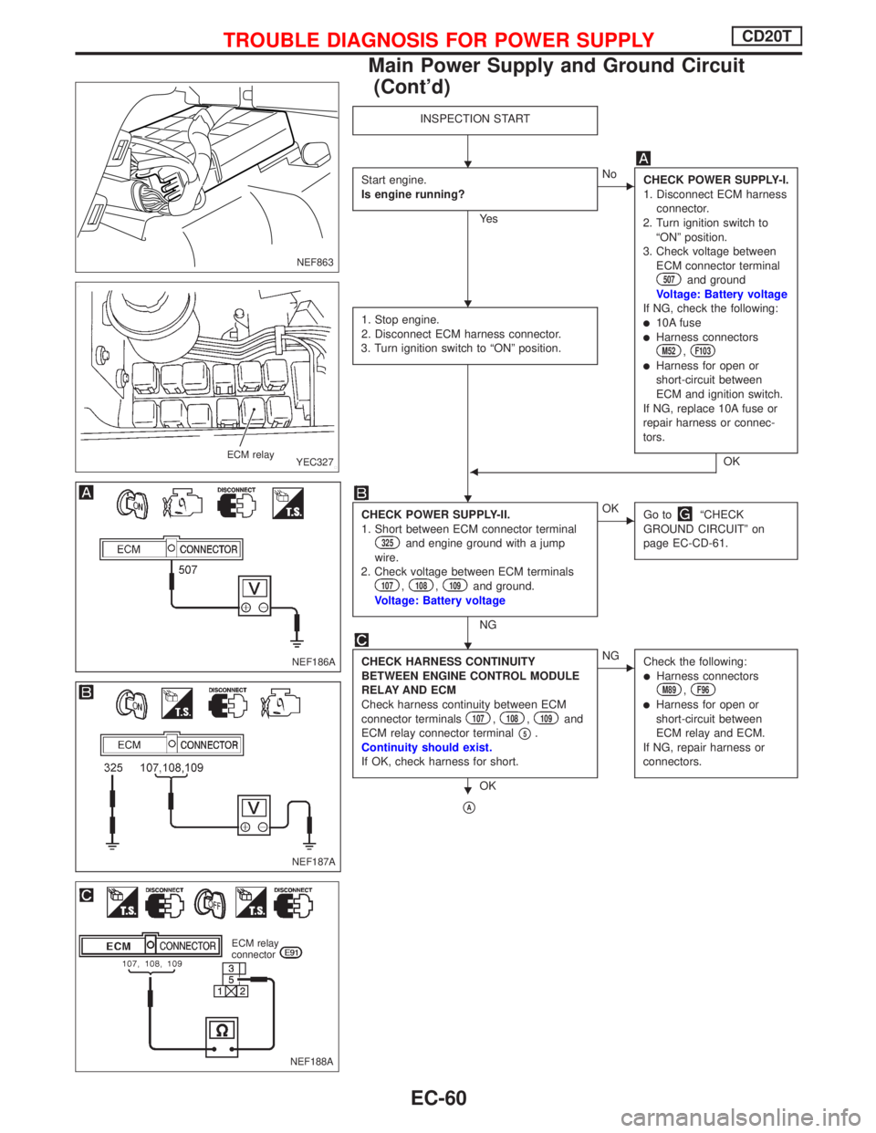
INSPECTION START
Start engine.
Is engine running?
Ye s
ENo
CHECK POWER SUPPLY-I.
1. Disconnect ECM harness
connector.
2. Turn ignition switch to
ªONº position.
3. Check voltage between
ECM connector terminal
507and ground
Voltage: Battery voltage
If NG, check the following:
l10A fuselHarness connectorsM52,F103
lHarness for open or
short-circuit between
ECM and ignition switch.
If NG, replace 10A fuse or
repair harness or connec-
tors.
OK 1. Stop engine.
2. Disconnect ECM harness connector.
3. Turn ignition switch to ªONº position.F
CHECK POWER SUPPLY-II.
1. Short between ECM connector terminal
325and engine ground with a jump
wire.
2. Check voltage between ECM terminals
107,108,109and ground.
Voltage: Battery voltage
NG
EOK
Go toªCHECK
GROUND CIRCUITº on
page EC-CD-61.
CHECK HARNESS CONTINUITY
BETWEEN ENGINE CONTROL MODULE
RELAY AND ECM
Check harness continuity between ECM
connector terminals
107,108,109and
ECM relay connector terminal
p5.
Continuity should exist.
If OK, check harness for short.
OK
ENG
Check the following:
lHarness connectorsM89,F96
lHarness for open or
short-circuit between
ECM relay and ECM.
If NG, repair harness or
connectors.
pA
NEF863
YEC327 ECM relay
NEF186A
NEF187A
NEF188A
ECM relay
connector
H
H
H
H
H
TROUBLE DIAGNOSIS FOR POWER SUPPLYCD20T
Main Power Supply and Ground Circuit
(Cont'd)
EC-60
Page 355 of 2267
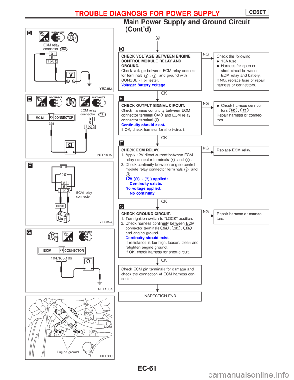
pA
CHECK VOLTAGE BETWEEN ENGINE
CONTROL MODULE RELAY AND
GROUND.
Check voltage between ECM relay connec-
tor terminals
p2,p3and ground with
CONSULT-II or tester.
Voltage: Battery voltage
OK
ENG
Check the following:
l15A fuselHarness for open or
short-circuit between
ECM relay and battery.
If NG, replace fuse or repair
harness or connectors.
CHECK OUTPUT SIGNAL CIRCUIT.
Check harness continuity between ECM
connector terminal
325and ECM relay
connector terminal
p1.
Continuity should exist.
If OK, check harness for short-circuit.
OK
ENGlCheck harness connec-
torsE43,F2
Repair harness or connec-
tors.
CHECK ECM RELAY.
1. Apply 12V direct current between ECM
relay connector terminals
p1andp2.
2. Check continuity between engine control
module relay connector terminals
p3and
p5.
12V (
p1-p2) applied:
Continuity exists.
No voltage applied:
No continuity
OK
ENG
Replace ECM relay.
CHECK GROUND CIRCUIT.
1. Turn ignition switch to ªLOCKº position.
2. Check harness continuity between ECM
connector terminals
104,105,106
and engine ground.
Continuity should exist.
If resistance is too high, loosen, clean and
retighten engine ground.
If OK, check harness for short-circuit.
OK
ENG
Repair harness or connec-
tors.
Check ECM pin terminals for damage and
check the connection of ECM harness con-
nector.
INSPECTION END
YEC352 ECM relay
connector
NEF189A ECM relay
connector
YEC354 ECM relay
connector
NEF190A
NEF399 Engine ground
H
H
H
H
H
H
TROUBLE DIAGNOSIS FOR POWER SUPPLYCD20T
Main Power Supply and Ground Circuit
(Cont'd)
EC-61
Page 365 of 2267
MODELS BEFORE VIN - P11U0583350
YEC801
BATTERYIGNITION SWITCH
ON or START
FUSE
BLOCK
(J/B)Refer to EL-POWER.
: Dectable line for DTC
: Non-detectable line for DTC
VEHICLE
SPEED
SENSOR COMBINATION
METER
(SPEEDOMETER)
ECM
REFER TO THE FOLLOWING
FUSE BLOCK - Junction Box (J/B)
TROUBLE DIAGNOSIS 3CD20T
Vehicle Speed Sensor (VSS) (Cont'd)
EC-71