Page 184 of 2267
Wiring Diagram Ð ABS Ð
MODELS WITH SELF-DIAGNOSIS FUNCTION
YBR208 BATTERYIGNITION SWITCH
ON or START
FUSE
BLOCK
(J/B)Refer to EL-POWER.
: LHD models
: RHD models: CVT models
: M/T models
RELEASEDDEPRESSEDSTOP LAMP
SWITCH
FUSE
BLOCK
(J/B)COMBINATION METER
(ABS WARNING LAMP)
ABS ACTUATOR
AND ELECTRIC
UNIT
(CONTROL UNIT)
TCM
(TRANSMISSION CON-
TROL MODULE)DATA LINK CON-
NECTOR
Refer to las page (Foldout page).
TROUBLE DIAGNOSES
BR-62
Page 192 of 2267
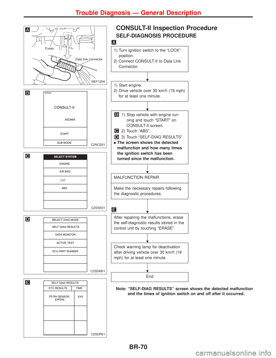
CONSULT-II Inspection Procedure
SELF-DIAGNOSIS PROCEDURE
1) Turn ignition switch to the ªLOCKº
position.
2) Connect CONSULT-II to Data Link
Connector.
1) Start engine.
2) Drive vehicle over 30 km/h (19 mph)
for at least one minute.
1) Stop vehicle with engine run-
ning and touch ªSTARTº on
CONSULT-II screen.
2) Touch ªABSº.
3) Touch ªSELF-DIAG RESULTSº.
lThe screen shows the detected
malfunction and how many times
the ignition switch has been
turned since the malfunction.
MALFUNCTION REPAIR
----------------------------------------------------------------------------------------------------------------------------------------------------------------------------------------------------------------------------------------------------------------------------------------------------------
Make the necessary repairs following
the diagnostic procedures.
After repairing the malfunctions, erase
the self-diagnostic results stored in the
control unit by touching ªERASEº.
Check warning lamp for deactivation
after driving vehicle over 30 km/h (19
mph) for at least one minute.
End
Note: ªSELF-DIAG RESULTSº screen shows the detected malfunction
and the times of ignition switch on and off after it occurred.
.NEF125A
Fuses
Data link connector
C2NCS01
C2SSE01
.CVT
C2SDM01
C2SDR01
H
H
H
H
H
H
Trouble Diagnosis Ð General Description
BR-70
Page 198 of 2267
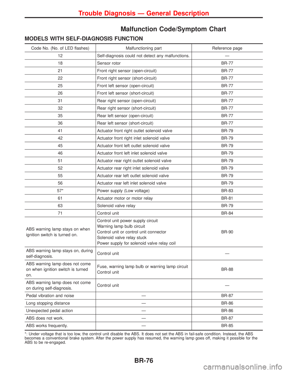
Malfunction Code/Symptom Chart
MODELS WITH SELF-DIAGNOSIS FUNCTION
Code No. (No. of LED flashes) Malfunctioning part Reference page
12 Self-diagnosis could not detect any malfunctions. Ð
18 Sensor rotor BR-77
21 Front right sensor (open-circuit) BR-77
22 Front right sensor (short-circuit) BR-77
25 Front left sensor (open-circuit) BR-77
26 Front left sensor (short-circuit) BR-77
31 Rear right sensor (open-circuit) BR-77
32 Rear right sensor (short-circuit) BR-77
35 Rear left sensor (open-circuit) BR-77
36 Rear left sensor (short-circuit) BR-77
41 Actuator front right outlet solenoid valve BR-79
42 Actuator front right inlet solenoid valve BR-79
45 Actuator front left outlet solenoid valve BR-79
46 Actuator front left inlet solenoid valve BR-79
51 Actuator rear right outlet solenoid valve BR-79
52 Actuator rear right inlet solenoid valve BR-79
55 Actuator rear left outlet solenoid valve BR-79
56 Actuator rear left inlet solenoid valve BR-79
57* Power supply (Low voltage) BR-83
61 Actuator motor or motor relay BR-81
63 Solenoid valve relay BR-79
71 Control unit BR-84
ABS warning lamp stays on when
ignition switch is turned on.Control unit power supply circuit
Warning lamp bulb circuit
Control unit or control unit connector
Solenoid valve relay stuck
Power supply for solenoid valve relay coilBR-90
ABS warning lamp stays on, during
self-diagnosis.Control unit Ð
ABS warning lamp does not come
on when ignition switch is turned
on.Fuse, warning lamp bulb or warning lamp circuit
Control unitBR-88
ABS warning lamp does not come
on during self-diagnosis.Control unit Ð
Pedal vibration and noise Ð BR-87
Long stopping distance Ð BR-86
Unexpected pedal action Ð BR-86
ABS does not work. Ð BR-87
ABS works frequently. Ð BR-85
*: Under voltage that is too low, the control unit disable the ABS. It does not set the ABS in fail-safe condition. Instead, the ABS
becomes a conventional brake system. After the power supply has resumed, the warning lamp goes off, making it possible for the
ABS to be re-engaged.
Trouble Diagnosis Ð General Description
BR-76
Page 201 of 2267
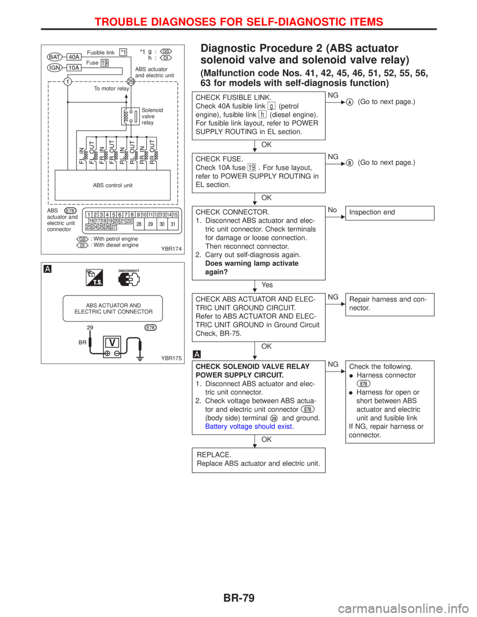
Diagnostic Procedure 2 (ABS actuator
solenoid valve and solenoid valve relay)
(Malfunction code Nos. 41, 42, 45, 46, 51, 52, 55, 56,
63 for models with self-diagnosis function)
CHECK FUSIBLE LINK.
Check 40A fusible link
g(petrol
engine), fusible link
h(diesel engine).
For fusible link layout, refer to POWER
SUPPLY ROUTING in EL section.
OK
ENGpA(Go to next page.)
CHECK FUSE.
Check 10A fuse
19. For fuse layout,
refer to POWER SUPPLY ROUTING in
EL section.
OK
ENGpB(Go to next page.)
CHECK CONNECTOR.
1. Disconnect ABS actuator and elec-
tric unit connector. Check terminals
for damage or loose connection.
Then reconnect connector.
2. Carry out self-diagnosis again.
Does warning lamp activate
again?
Ye s
ENo
Inspection end
CHECK ABS ACTUATOR AND ELEC-
TRIC UNIT GROUND CIRCUIT.
Refer to ABS ACTUATOR AND ELEC-
TRIC UNIT GROUND in Ground Circuit
Check, BR-75.
OK
ENG
Repair harness and con-
nector.
CHECK SOLENOID VALVE RELAY
POWER SUPPLY CIRCUIT.
1. Disconnect ABS actuator and elec-
tric unit connector.
2. Check voltage between ABS actua-
tor and electric unit connector
E78
(body side) terminalp29and ground.
Battery voltage should exist.
OK
ENG
Check the following.
lHarness connector
E78
lHarness for open or
short between ABS
actuator and electric
unit and fusible link
If NG, repair harness or
connector.
REPLACE.
Replace ABS actuator and electric unit.
YBR174 Fusible link
Fuse
ABS actuator
and electric unit
To motor relay
Solenoid
valve
relay
ABS control unit
ABS
actuator and
electric unit
connector
: With petrol engine
: With diesel engine
YBR175
ABS ACTUATOR AND
ELECTRIC UNIT CONNECTOR
H
H
H
H
H
TROUBLE DIAGNOSES FOR SELF-DIAGNOSTIC ITEMS
BR-79
Page 202 of 2267
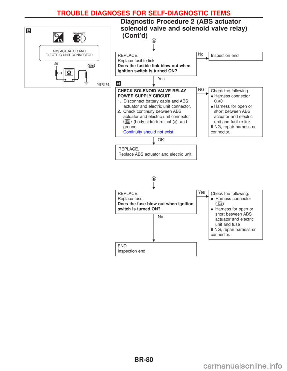
pA
REPLACE.
Replace fusible link.
Does the fusible link blow out when
ignition switch is turned ON?
Ye s
ENo
Inspection end
CHECK SOLENOID VALVE RELAY
POWER SUPPLY CIRCUIT.
1. Disconnect battery cable and ABS
actuator and electric unit connector.
2. Check continuity between ABS
actuator and electric unit connector
E78(body side) terminalp29and
ground.
Continuity should not exist.
OK
ENG
Check the following
lHarness connector
E78
lHarness for open or
short between ABS
actuator and electric
unit and fusible link
If NG, repair harness or
connector.
REPLACE.
Replace ABS actuator and electric unit.
pB
REPLACE.
Replace fuse.
Does the fuse blow out when ignition
switch is turned ON?
No
EYe s
Check the following.
lHarness connector
E78
lHarness for open or
short between ABS
actuator and electric
unit and fuse
If NG, repair harness or
connector.
END
Inspection end
YBR176
ABS ACTUATOR AND
ELECTRIC UNIT CONNECTORH
H
H
H
H
TROUBLE DIAGNOSES FOR SELF-DIAGNOSTIC ITEMS
Diagnostic Procedure 2 (ABS actuator
solenoid valve and solenoid valve relay)
(Cont'd)
BR-80
Page 203 of 2267
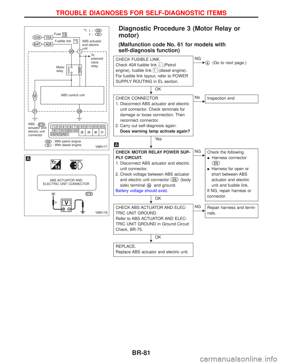
Diagnostic Procedure 3 (Motor Relay or
motor)
(Malfunction code No. 61 for models with
self-diagnosis function)
CHECK FUSIBLE LINK.
Check 40A fusible link
i(Petrol
engine), fusible link
f(diesel engine).
For fusible link layout, refer to POWER
SUPPLY ROUTING in EL section.
OK
ENG
pA(Go to next page.)
CHECK CONNECTOR
1. Disconnect ABS actuator and electric
unit connector. Check terminals for
damage or loose connection. Then
reconnect connector.
2. Carry out self-diagnosis again.
Does warning lamp activate again?
Ye s
ENo
Inspection end
CHECK MOTOR RELAY POWER SUP-
PLY CIRCUIT.
1. Disconnect ABS actuator and electric
unit connector.
2. Check voltage between ABS actuator
and electric unit connector
E78(body
side) terminal
p30and ground.
Battery voltage should exist.
OK
ENG
Check the following.
lHarness connector
E78
lHarness for open or
short between ABS
actuator and electric
unit and fusible link.
If NG, repair harness or
connector.
CHECK ABS ACTUATOR AND ELEC-
TRIC UNIT GROUND.
Refer to ABS ACTUATOR AND ELEC-
TRIC UNIT GROUND in Ground Circuit
Check, BR-75.
OK
ENG
Repair harness and termi-
nals.
REPLACE.
Replace ABS actuator and electric unit.
YBR177 Fusible link Fuse
ABS actuator
and electric
unit
Motor
relayTo
solenoid
valve
relay
ABS control unit
ABS
actuator and
electric unit
connector
: With petrol engine
: With diesel engine
YBR178
ABS ACTUATOR AND
ELECTRIC UNIT CONNECTOR
H
H
H
H
TROUBLE DIAGNOSES FOR SELF-DIAGNOSTIC ITEMS
BR-81
Page 205 of 2267
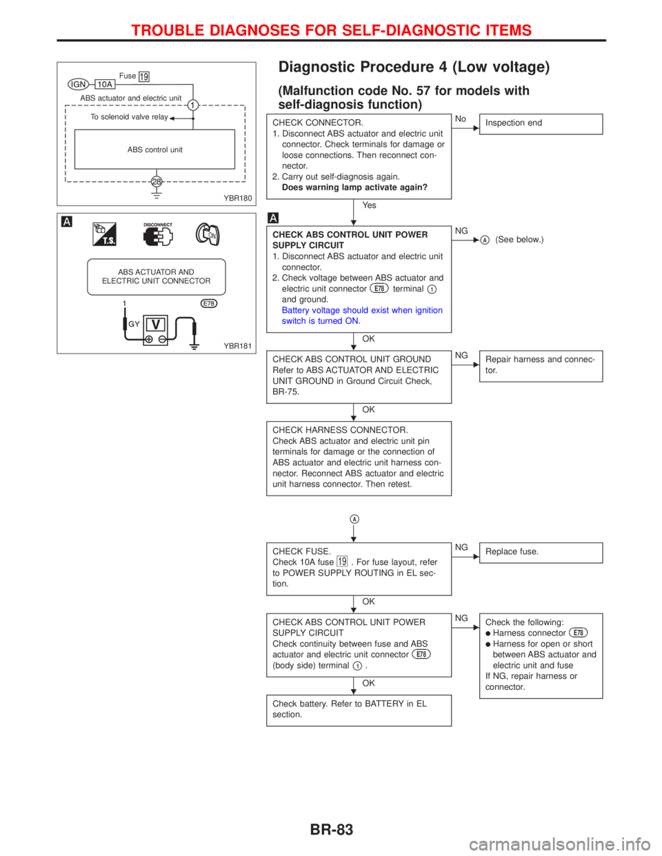
Diagnostic Procedure 4 (Low voltage)
(Malfunction code No. 57 for models with
self-diagnosis function)
CHECK CONNECTOR.
1. Disconnect ABS actuator and electric unit
connector. Check terminals for damage or
loose connections. Then reconnect con-
nector.
2. Carry out self-diagnosis again.
Does warning lamp activate again?
Ye s
ENo
Inspection end
CHECK ABS CONTROL UNIT POWER
SUPPLY CIRCUIT
1. Disconnect ABS actuator and electric unit
connector.
2. Check voltage between ABS actuator and
electric unit connector
E78terminalp1and ground.
Battery voltage should exist when ignition
switch is turned ON.
OK
ENGpA(See below.)
CHECK ABS CONTROL UNIT GROUND
Refer to ABS ACTUATOR AND ELECTRIC
UNIT GROUND in Ground Circuit Check,
BR-75.
OK
ENG
Repair harness and connec-
tor.
CHECK HARNESS CONNECTOR.
Check ABS actuator and electric unit pin
terminals for damage or the connection of
ABS actuator and electric unit harness con-
nector. Reconnect ABS actuator and electric
unit harness connector. Then retest.
pA
CHECK FUSE.
Check 10A fuse19. For fuse layout, refer
to POWER SUPPLY ROUTING in EL sec-
tion.
OK
ENG
Replace fuse.
CHECK ABS CONTROL UNIT POWER
SUPPLY CIRCUIT
Check continuity between fuse and ABS
actuator and electric unit connector
E78
(body side) terminalp1.
OK
ENG
Check the following:
lHarness connectorE78
lHarness for open or short
between ABS actuator and
electric unit and fuse
If NG, repair harness or
connector.
Check battery. Refer to BATTERY in EL
section.
YBR180 ABS control unit To solenoid valve relay ABS actuator and electric unit
.Fuse
YBR181
ABS ACTUATOR AND
ELECTRIC UNIT CONNECTOR
H
H
H
H
H
H
TROUBLE DIAGNOSES FOR SELF-DIAGNOSTIC ITEMS
BR-83
Page 206 of 2267
Diagnostic Procedure 5 (Control unit)
(Malfunctioning code No. 71 for models with
self-diagnosis function)
CHECK CONNECTOR.
1. Disconnect ABS actuator and electric unit
connector.
Check terminals for damage or loose con-
nections. Then reconnect connector.
2. Carry out self-diagnosis again.
Does warning lamp activate again?
Ye s
ENo
Inspection end
ABS CONTROL UNIT POWER SUPPLY
CHECK
Check voltage. Refer to
in Diagnostic
Procedure 4, BR-83.
CHECK SELF-DIAGNOSTIC RESULTS
Does warning lamp indicate code No. 71
again?
No
EYe s
Replace ABS actuator and
electric unit.
INSPECTION
Inspect the system according to the code
No.
YBR182 ABS control unit ABS actuator and electric unit
.Fuse
H
H
H
TROUBLE DIAGNOSES FOR SELF-DIAGNOSTIC ITEMS
BR-84