Page 47 of 2267
Wiring Diagram Ð CVT Ð MAINNCAT0031
YAT201
BATTERY
ENGINE
CONTROL
MODULE
RELAY
OFFONSTOP
LAMP
SWITCH
FUSE
BLOCK
(J/B)OFFONSTOP
LAMP
SWITCH: Detectable line for DTC
: Non-detectable line for DTC
: LHD models
: RHD models Refer to EL-POWER. FUSE
BLOCK
(J/B)
TCM
(TRANSMISSION
CONTROL
MODULE)
Refer to last page
(foldout page). ECM
TROUBLE DIAGNOSIS FOR POWER SUPPLY
Wiring Diagram Ð CVT Ð MAIN
AT-45
Page 48 of 2267
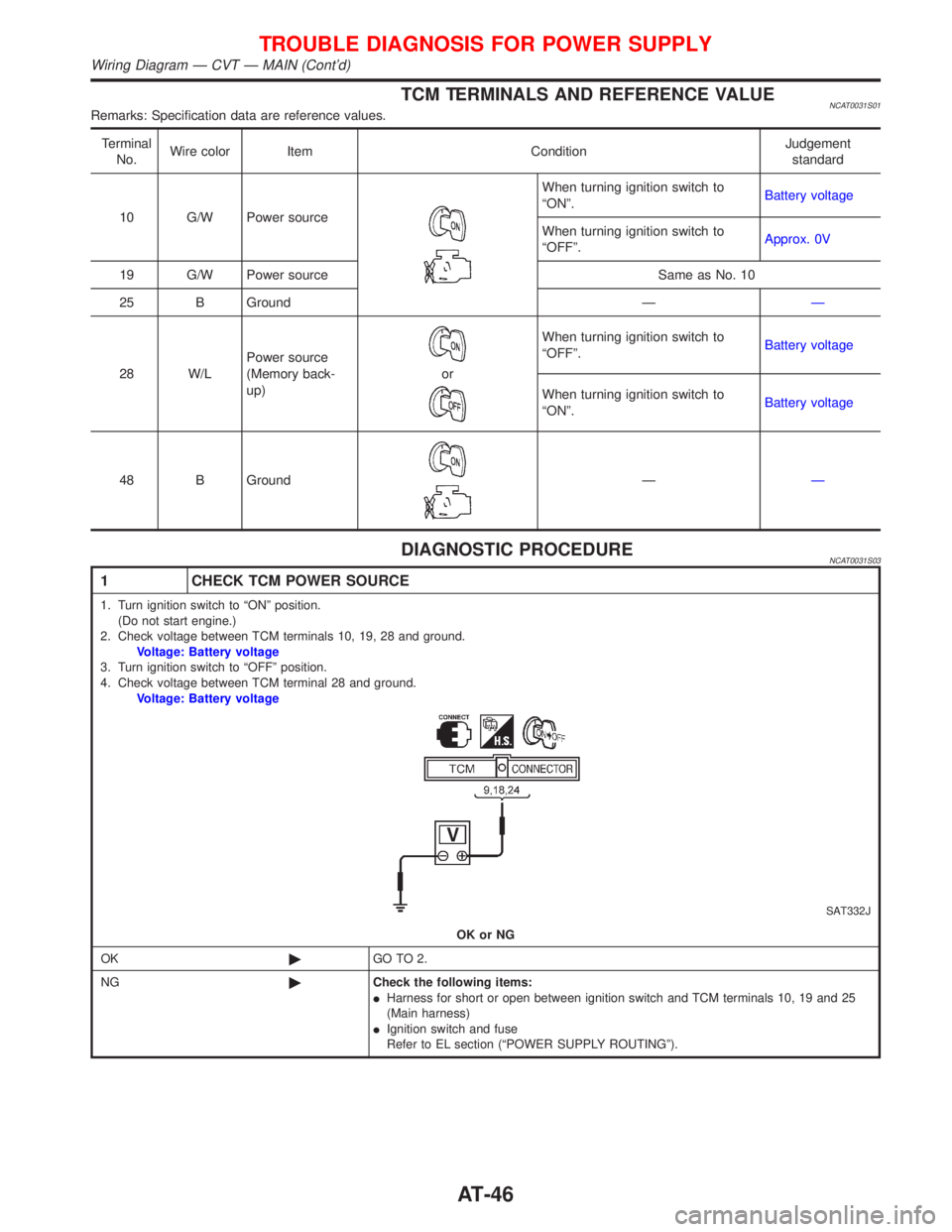
TCM TERMINALS AND REFERENCE VALUENCAT0031S01Remarks: Specification data are reference values.
Terminal
No.Wire color Item ConditionJudgement
standard
10 G/W Power source
When turning ignition switch to
ªONº.Battery voltage
When turning ignition switch to
ªOFFº.Approx. 0V
19 G/W Power source Same as No. 10
25 B Ground ÐÐ
28 W/LPower source
(Memory back-
up)
or
When turning ignition switch to
ªOFFº.Battery voltage
When turning ignition switch to
ªONº.Battery voltage
48 B Ground
ÐÐ
DIAGNOSTIC PROCEDURENCAT0031S03
1 CHECK TCM POWER SOURCE
1. Turn ignition switch to ªONº position.
(Do not start engine.)
2. Check voltage between TCM terminals 10, 19, 28 and ground.
Voltage: Battery voltage
3. Turn ignition switch to ªOFFº position.
4. Check voltage between TCM terminal 28 and ground.
Voltage: Battery voltage
SAT332J
OK or NG
OK©GO TO 2.
NG©Check the following items:
IHarness for short or open between ignition switch and TCM terminals 10, 19 and 25
(Main harness)
IIgnition switch and fuse
Refer to EL section (ªPOWER SUPPLY ROUTINGº).
TROUBLE DIAGNOSIS FOR POWER SUPPLY
Wiring Diagram Ð CVT Ð MAIN (Cont'd)
AT-46
Page 53 of 2267
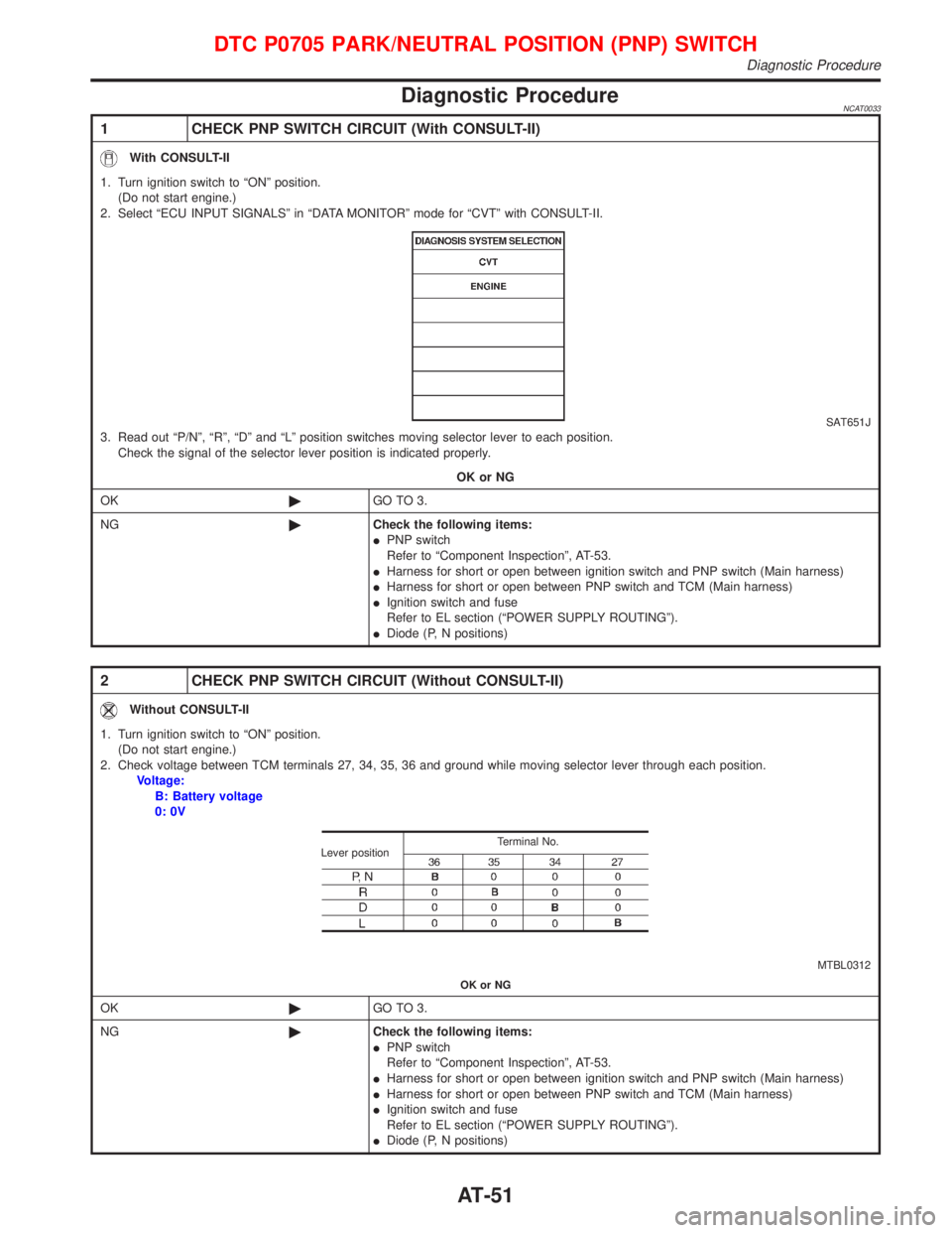
Diagnostic ProcedureNCAT0033
1 CHECK PNP SWITCH CIRCUIT (With CONSULT-II)
With CONSULT-II
1. Turn ignition switch to ªONº position.
(Do not start engine.)
2. Select ªECU INPUT SIGNALSº in ªDATA MONITORº mode for ªCVTº with CONSULT-II.
SAT651J3. Read out ªP/Nº, ªRº, ªDº and ªLº position switches moving selector lever to each position.
Check the signal of the selector lever position is indicated properly.
OK or NG
OK©GO TO 3.
NG©Check the following items:
IPNP switch
Refer to ªComponent Inspectionº, AT-53.
IHarness for short or open between ignition switch and PNP switch (Main harness)
IHarness for short or open between PNP switch and TCM (Main harness)
IIgnition switch and fuse
Refer to EL section (ªPOWER SUPPLY ROUTINGº).
IDiode (P, N positions)
2 CHECK PNP SWITCH CIRCUIT (Without CONSULT-II)
Without CONSULT-II
1. Turn ignition switch to ªONº position.
(Do not start engine.)
2. Check voltage between TCM terminals 27, 34, 35, 36 and ground while moving selector lever through each position.
Voltage:
B: Battery voltage
0: 0V
MTBL0312 Terminal No.
Lever position
OK or NG
OK©GO TO 3.
NG©Check the following items:
IPNP switch
Refer to ªComponent Inspectionº, AT-53.
IHarness for short or open between ignition switch and PNP switch (Main harness)
IHarness for short or open between PNP switch and TCM (Main harness)
IIgnition switch and fuse
Refer to EL section (ªPOWER SUPPLY ROUTINGº).
IDiode (P, N positions)
DTC P0705 PARK/NEUTRAL POSITION (PNP) SWITCH
Diagnostic Procedure
AT-51
Page 108 of 2267
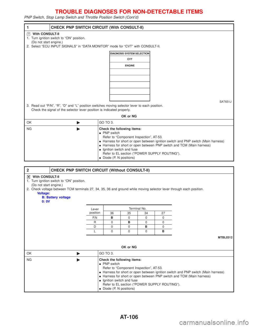
1 CHECK PNP SWITCH CIRCUIT (With CONSULT-II)
With CONSULT-II
1. Turn ignition switch to ªONº position.
(Do not start engine.)
2. Select ªECU INPUT SIGNALSº in ªDATA MONITORº mode for ªCVTº with CONSULT-II.
SAT651J3. Read out ªP/Nº, ªRº, ªDº and ªLº position switches moving selector lever to each position.
Check the signal of the selector lever position is indicated properly.
OK or NG
OK©GO TO 3.
NG©Check the following items:
IPNP switch
Refer to ªComponent Inspectionº, AT-53.
IHarness for short or open between ignition switch and PNP switch (Main harness)
IHarness for short or open between PNP switch and TCM (Main harness)
IIgnition switch and fuse
Refer to EL section (ªPOWER SUPPLY ROUTINGº).
IDiode (P, N positions)
2 CHECK PNP SWITCH CIRCUIT (Without CONSULT-II)
With CONSULT-II
1. Turn ignition switch to ªONº position.
(Do not start engine.)
2. Check voltage between TCM terminals 27, 34, 35, 36 and ground while moving selector lever through each position.
Voltage:
B: Battery voltage
0: 0V
OK or NG
OK©GO TO 3.
NG©Check the following items:
IPNP switch
Refer to ªComponent Inspectionº, AT-53.
IHarness for short or open between ignition switch and PNP switch (Main harness)
IHarness for short or open between PNP switch and TCM (Main harness)
IIgnition switch and fuse
Refer to EL section (ªPOWER SUPPLY ROUTINGº).
IDiode (P, N positions)
Lever
positionTerminal No.
36 35 34 27
P, NB000
R0B00
D0 0B0
L000B
MTBL0312
TROUBLE DIAGNOSES FOR NON-DETECTABLE ITEMS
PNP Switch, Stop Lamp Switch and Throttle Position Switch (Cont'd)
AT-106
Page 109 of 2267
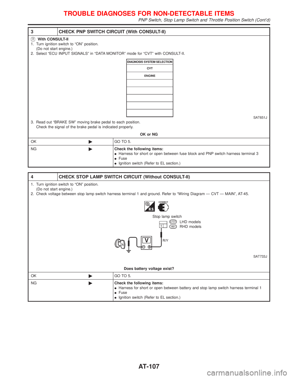
3 CHECK PNP SWITCH CIRCUIT (With CONSULT-II)
With CONSULT-II
1. Turn ignition switch to ªONº position.
(Do not start engine.)
2. Select ªECU INPUT SIGNALSº in ªDATA MONITORº mode for ªCVTº with CONSULT-II.
SAT651J3. Read out ªBRAKE SWº moving brake pedal to each position.
Check the signal of the brake pedal is indicated properly.
OK or NG
OK©GO TO 5.
NG©Check the following items:
IHarness for short or open between fuse block and PNP switch harness terminal 3
IFuse
IIgnition switch (Refer to EL section.)
4 CHECK STOP LAMP SWITCH CIRCUIT (Without CONSULT-II)
1. Turn ignition switch to ªONº position.
(Do not start engine.)
2. Check voltage between stop lamp switch harness terminal 1 and ground. Refer to ªWiring Diagram Ð CVT Ð MAINº, AT-45.
SAT733J
Stop lamp switch
LHD models
RHD models
Does battery voltage exist?
OK©GO TO 5.
NG©Check the following items:
IHarness for short or open between battery and stop lamp switch harness terminal 1
IFuse
IIgnition switch (Refer to EL section.)
TROUBLE DIAGNOSES FOR NON-DETECTABLE ITEMS
PNP Switch, Stop Lamp Switch and Throttle Position Switch (Cont'd)
AT-107
Page 112 of 2267
Wiring Diagram Ð AT Ð NONDTC
MODELS BEFORE VIN - P11U0548750NCAT0237
YAT155
BATTERYIGNITION SWITCH
ON or START
FUSE
BLOCK
(J/B)Refer to
EL-POWER.TCM
(TRANSMISSION
CONTROL MODULE)
Detectable line for DTC
Non-detectable line for DTC
Hyper CVT models
Hyper CVT M6 models
SPORT indicator lamp
CVT warning lamp
UNIFIED METER CONTROL UNITCOMBINATION
METER
INDICATOR
CONTROL
UNIT
REFER TO THE FOLLOWING
FUSE BLOCK - Junction Box (J/B)
TROUBLE DIAGNOSES FOR NON-DETECTABLE ITEMS
Wiring Diagram Ð AT Ð NONDTC
AT-110
Page 130 of 2267
2. Use medium brake pedal/foot effort to bring the vehicle to a
complete stop from 50 km/h (31 MPH). Adjust brake pedal/
foot pressure such that vehicle stopping time equals 3 to 5
seconds.
3. To cool the brake system, drive the vehicle at 50 km/h (31
MPH) for 1 minute without stopping.
4. Repeat steps 1 to 3, 10 times or more to complete the bur-
nishing procedure.
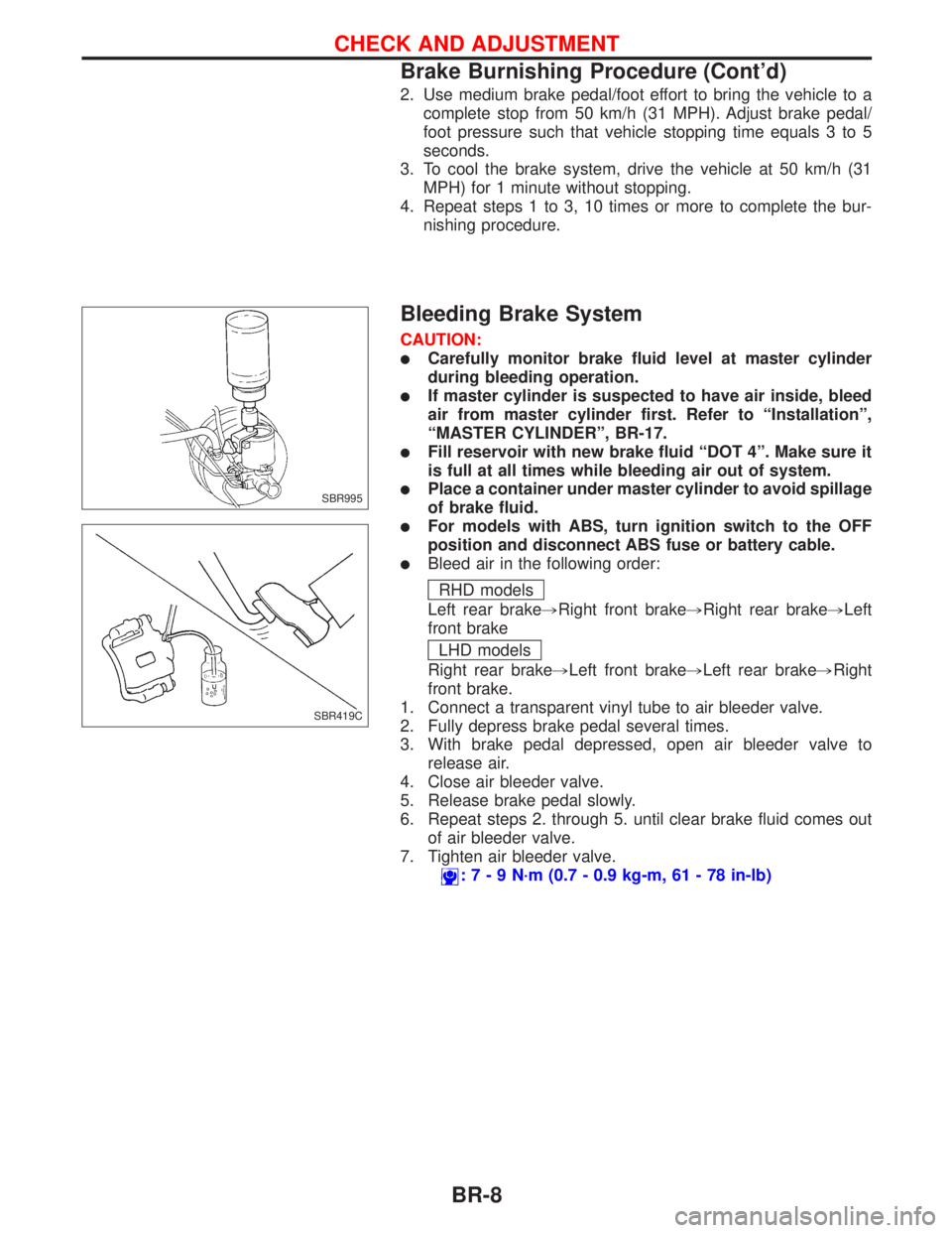
Bleeding Brake System
CAUTION:
lCarefully monitor brake fluid level at master cylinder
during bleeding operation.
lIf master cylinder is suspected to have air inside, bleed
air from master cylinder first. Refer to ªInstallationº,
ªMASTER CYLINDERº, BR-17.
lFill reservoir with new brake fluid ªDOT 4º. Make sure it
is full at all times while bleeding air out of system.
lPlace a container under master cylinder to avoid spillage
of brake fluid.
lFor models with ABS, turn ignition switch to the OFF
position and disconnect ABS fuse or battery cable.
lBleed air in the following order:
RHD models
Left rear brake,Right front brake,Right rear brake,Left
front brake
LHD models
Right rear brake,Left front brake,Left rear brake,Right
front brake.
1. Connect a transparent vinyl tube to air bleeder valve.
2. Fully depress brake pedal several times.
3. With brake pedal depressed, open air bleeder valve to
release air.
4. Close air bleeder valve.
5. Release brake pedal slowly.
6. Repeat steps 2. through 5. until clear brake fluid comes out
of air bleeder valve.
7. Tighten air bleeder valve.
:7-9N´m(0.7 - 0.9 kg-m, 61 - 78 in-lb)
SBR995
SBR419C
CHECK AND ADJUSTMENT
Brake Burnishing Procedure (Cont'd)
BR-8
Page 181 of 2267
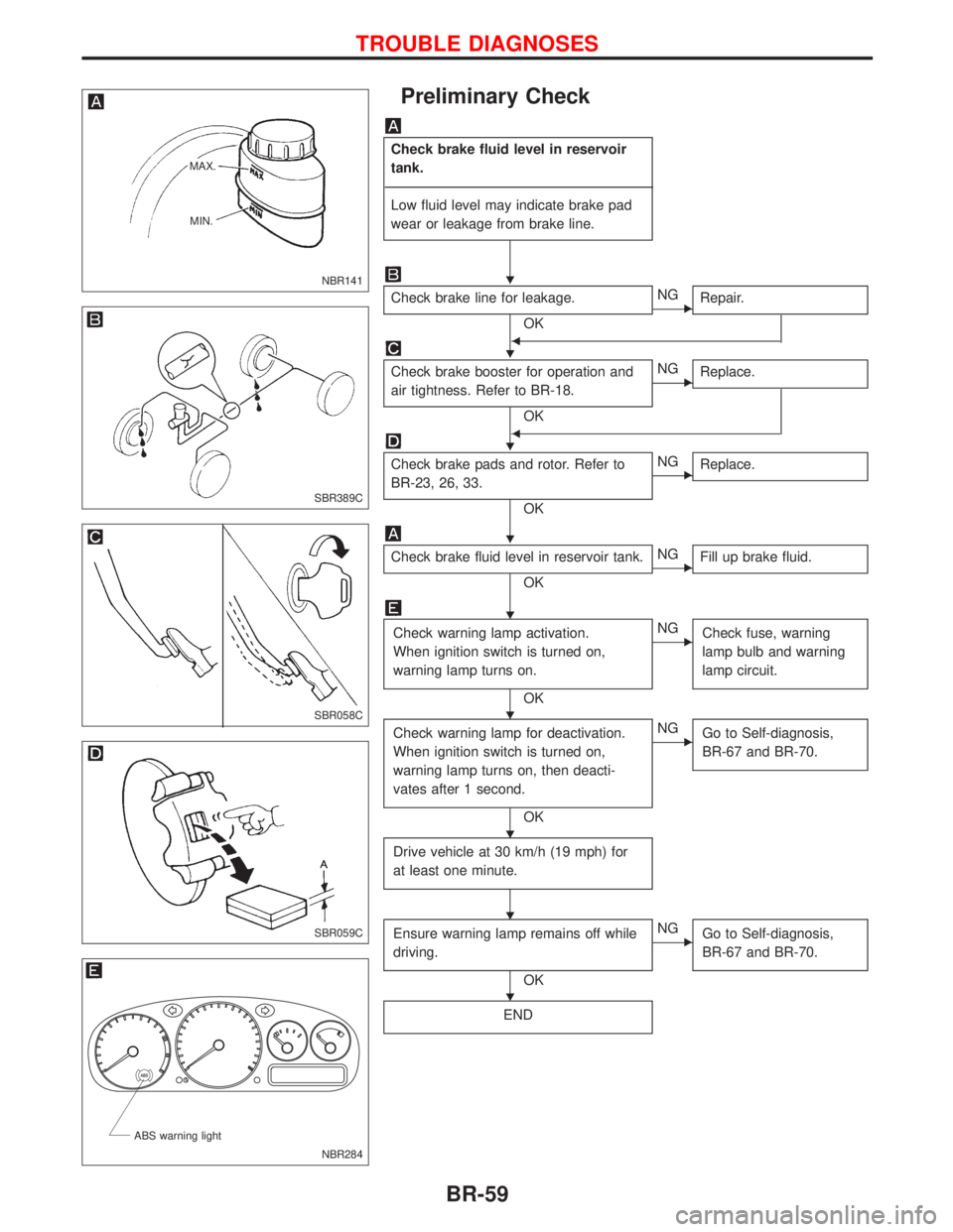
Preliminary Check
Check brake fluid level in reservoir
tank.
------------------------------------------------------------------------------------------------------------------------------------------------------------------------------------------------------------------------------------------------------------------------------------------------------------
Low fluid level may indicate brake pad
wear or leakage from brake line.
Check brake line for leakage.
OK
ENG
Repair.
F
Check brake booster for operation and
air tightness. Refer to BR-18.
OK
ENG
Replace.
F
Check brake pads and rotor. Refer to
BR-23, 26, 33.
OK
ENG
Replace.
Check brake fluid level in reservoir tank.
OK
ENG
Fill up brake fluid.
Check warning lamp activation.
When ignition switch is turned on,
warning lamp turns on.
OK
ENG
Check fuse, warning
lamp bulb and warning
lamp circuit.
Check warning lamp for deactivation.
When ignition switch is turned on,
warning lamp turns on, then deacti-
vates after 1 second.
OK
ENG
Go to Self-diagnosis,
BR-67 and BR-70.
Drive vehicle at 30 km/h (19 mph) for
at least one minute.
Ensure warning lamp remains off while
driving.
OK
ENG
Go to Self-diagnosis,
BR-67 and BR-70.
END
NBR141 MAX.
MIN.
SBR389C
SBR058C
SBR059C
.
NBR284 ABS warning light
H
H
H
H
H
H
H
H
H
TROUBLE DIAGNOSES
BR-59