Page 416 of 2267
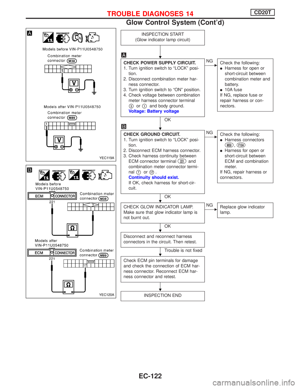
INSPECTION START
(Glow indicator lamp circuit)
CHECK POWER SUPPLY CIRCUIT.
1. Turn ignition switch to ªLOCKº posi-
tion.
2. Disconnect combination meter har-
ness connector.
3. Turn ignition switch to ªONº position.
4. Check voltage between combination
meter harness connector terminal
p5orp1and body ground.
Voltage: Battery voltage
OK
ENG
Check the following:
lHarness for open or
short-circuit between
combination meter and
battery.
l10A fuse
If NG, replace fuse or
repair harness or con-
nectors.
CHECK GROUND CIRCUIT.
1. Turn ignition switch to ªLOCKº posi-
tion.
2. Disconnect ECM harness connector.
3. Check harness continuity between
ECM connector terminal
221and
combination meter connector termi-
nal
p7orp17.
Continuity should exist.
If OK, check harness for short-cir-
cuit.
OK
ENG
Check the following:
lHarness connectors
M50,F104
lHarness for open or
short-circuit between
ECM and combination
meter.
If NG, repair harness or
connectors.
CHECK GLOW INDICATOR LAMP.
Make sure that glow indicator lamp is
not burnt out.
OK
ENG
Replace glow indicator
lamp.
Disconnect and reconnect harness
connectors in the circuit. Then retest.
Trouble is not fixed
Check ECM pin terminals for damage
and check the connection of ECM har-
ness connector. Reconnect ECM har-
ness connector and retest.
INSPECTION END
YEC119A
YEC120A
H
H
H
H
H
H
TROUBLE DIAGNOSES 14CD20T
Glow Control System (Cont'd)
EC-122
Page 421 of 2267
YEC813
IGNITION SWITCH
ON or START
FUSE
BLOCK
(J/B)
Refer to EL-POWER.
: Detectable line for DTC
: Non-detectable line for DTC
AIR CONDITIONER
RELAY
To compressor
(Refer to HA-A/C.)
A/C
CONTROL
PANEL
LOWHIGH
NORMALTRIPLE-
PRESSURE
SWITCH
THERMISTORTHERMO
CONTROL
AMP.
ECM
REFER TO THE FOLLOWING
FUSE BLOCK - Junction Box (J/B)
FUSE BLOCK - Junction Box (J/B)
TROUBLE DIAGNOSES 15CD20T
Air Conditioner Cut Control (Cont'd)
EC-127
Page 422 of 2267
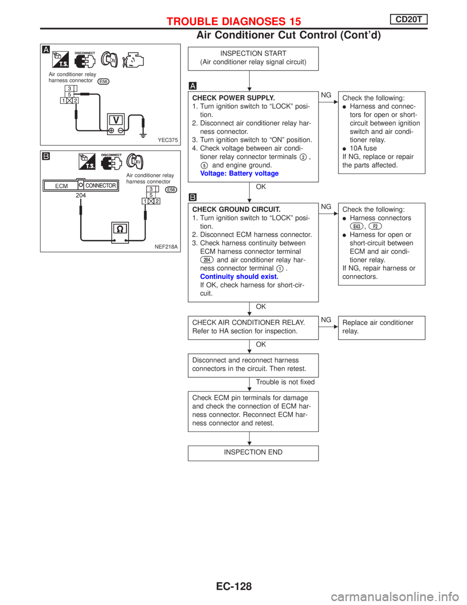
INSPECTION START
(Air conditioner relay signal circuit)
CHECK POWER SUPPLY.
1. Turn ignition switch to ªLOCKº posi-
tion.
2. Disconnect air conditioner relay har-
ness connector.
3. Turn ignition switch to ªONº position.
4. Check voltage between air condi-
tioner relay connector terminals
p2,
p5and engine ground.
Voltage: Battery voltage
OK
ENG
Check the following:
lHarness and connec-
tors for open or short-
circuit between ignition
switch and air condi-
tioner relay.
l10A fuse
If NG, replace or repair
the parts affected.
CHECK GROUND CIRCUIT.
1. Turn ignition switch to ªLOCKº posi-
tion.
2. Disconnect ECM harness connector.
3. Check harness continuity between
ECM harness connector terminal
204and air conditioner relay har-
ness connector terminal
p1.
Continuity should exist.
If OK, check harness for short-cir-
cuit.
OK
ENG
Check the following:
lHarness connectors
E43,F2
lHarness for open or
short-circuit between
ECM and air condi-
tioner relay.
If NG, repair harness or
connectors.
CHECK AIR CONDITIONER RELAY.
Refer to HA section for inspection.
OK
ENG
Replace air conditioner
relay.
Disconnect and reconnect harness
connectors in the circuit. Then retest.
Trouble is not fixed
Check ECM pin terminals for damage
and check the connection of ECM har-
ness connector. Reconnect ECM har-
ness connector and retest.
INSPECTION END
YEC375 Air conditioner relay
harness connector
Air conditioner relay
harness connector
NEF218A
H
H
H
H
H
H
TROUBLE DIAGNOSES 15CD20T
Air Conditioner Cut Control (Cont'd)
EC-128
Page 429 of 2267
COMPONENT INSPECTION
EGR valve
Apply vacuum to EGR vacuum port with a hand vacuum pump.
EGR valve spring should lift.
If NG, replace EGR valve.
EGRC-solenoid valve
Check air passage continuity.
ConditionAir passage
continuity
between
pAandpB
Air passage
continuity
between
pAandpC
12V direct current sup-
ply between terminals
p1andp2
Ye s N o
No supplyNo Yes
If NG, replace solenoid valve.
MEF137D EGR valve
MEC488B BATTERY FUSE
TROUBLE DIAGNOSES 16CD20T
EGRC-Solenoid Valve (Cont'd)
EC-135
Page 437 of 2267
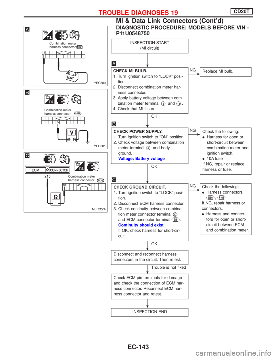
DIAGNOSTIC PROCEDURE: MODELS BEFORE VIN -
P11U0548750
INSPECTION START
(MI circuit)
CHECK MI BULB.
1. Turn ignition switch to ªLOCKº posi-
tion.
2. Disconnect combination meter har-
ness connector.
3. Apply battery voltage between com-
bination meter terminal
p5andp13.
4. Check that MI lits on.
OK
ENG
Replace MI bulb.
CHECK POWER SUPPLY.
1. Turn ignition switch to ªONº position.
2. Check voltage between combination
meter terminal
p5and body
ground.
Voltage: Battery voltage
OK
ENG
Check the following:
lHarness for open or
short-circuit between
combination meter and
ignition switch.
l10A fuse
If NG, repair or replace
harness or fuse.
CHECK GROUND CIRCUIT.
1. Turn ignition switch to ªLOCKº posi-
tion.
2. Disconnect ECM harness connector.
3. Check continuity between combina-
tion meter connector terminal
p13
and ECM connector terminal215.
Continuity should exist.
If OK, check harness for short-cir-
cuit.
OK
ENG
Check the following:
lHarness connectors
M50,F104
If NG, repair harness or
connectors.
lHarness and connec-
tors for open or short-
circuit between ECM
and combination meter.
Disconnect and reconnect harness
connectors in the circuit. Then retest.
Trouble is not fixed
Check ECM pin terminals for damage
and check the connection of ECM har-
ness connector. Reconnect ECM har-
ness connector and retest.
INSPECTION END
YEC380
Combination meter
harness connector
YEC381
Combination meter
harness connector
NEF222A
Combination meter
harness connector
H
H
H
H
H
H
TROUBLE DIAGNOSES 19CD20T
MI & Data Link Connectors (Cont'd)
EC-143
Page 438 of 2267
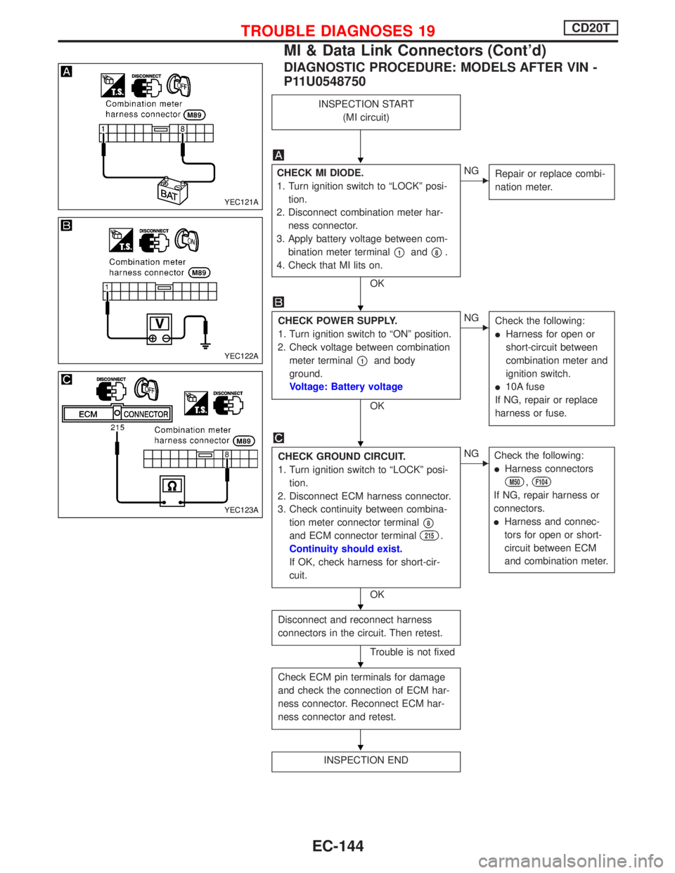
DIAGNOSTIC PROCEDURE: MODELS AFTER VIN -
P11U0548750
INSPECTION START
(MI circuit)
CHECK MI DIODE.
1. Turn ignition switch to ªLOCKº posi-
tion.
2. Disconnect combination meter har-
ness connector.
3. Apply battery voltage between com-
bination meter terminal
p1andp8.
4. Check that MI lits on.
OK
ENG
Repair or replace combi-
nation meter.
CHECK POWER SUPPLY.
1. Turn ignition switch to ªONº position.
2. Check voltage between combination
meter terminal
p1and body
ground.
Voltage: Battery voltage
OK
ENG
Check the following:
lHarness for open or
short-circuit between
combination meter and
ignition switch.
l10A fuse
If NG, repair or replace
harness or fuse.
CHECK GROUND CIRCUIT.
1. Turn ignition switch to ªLOCKº posi-
tion.
2. Disconnect ECM harness connector.
3. Check continuity between combina-
tion meter connector terminal
p8
and ECM connector terminal215.
Continuity should exist.
If OK, check harness for short-cir-
cuit.
OK
ENG
Check the following:
lHarness connectors
M50,F104
If NG, repair harness or
connectors.
lHarness and connec-
tors for open or short-
circuit between ECM
and combination meter.
Disconnect and reconnect harness
connectors in the circuit. Then retest.
Trouble is not fixed
Check ECM pin terminals for damage
and check the connection of ECM har-
ness connector. Reconnect ECM har-
ness connector and retest.
INSPECTION END
YEC121A
YEC122A
YEC123A
H
H
H
H
H
H
TROUBLE DIAGNOSES 19CD20T
MI & Data Link Connectors (Cont'd)
EC-144
Page 439 of 2267
Start Signal
YEC817 BATTERY
Refer to EL-POWER.
: Detectable line for DTC
: Non-detectable line for DTC
IGNITION
SWITCH
FUSE
BLOCK
(J/B)
ECM
REFER TO THE FOLLOWING
FUSE BLOCK - Junction Box (J/B)
FUSE BLOCK - Junction Box (J/B)
OFF
ST
ACC
ON
Refer to EL-POWER.
TROUBLE DIAGNOSES 20CD20T
EC-145
Page 440 of 2267
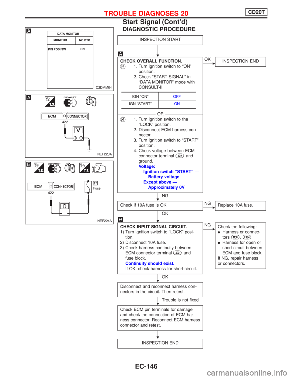
DIAGNOSTIC PROCEDURE
INSPECTION START
CHECK OVERALL FUNCTION.
1. Turn ignition switch to ªONº
position.
2. Check ªSTART SIGNALº in
ªDATA MONITORº mode with
CONSULT-II.
----------------------------------------------------------------------------------------------------------------------------------------OR----------------------------------------------------------------------------------------------------------------------------------------
1. Turn ignition switch to the
ªLOCKº position.
2. Disconnect ECM harness con-
nector.
3. Turn ignition switch to ªSTARTº
position.
4. Check voltage between ECM
connector terminal
422and
ground.
Voltage:
Ignition switch ªSTARTº Ð
Battery voltage
Except above Ð
Approximately 0V
NG
EOK
INSPECTION END
Check if 10A fuse is OK.
OK
ENG
Replace 10A fuse.
CHECK INPUT SIGNAL CIRCUIT.
1) Turn ignition switch to ªLOCKº posi-
tion.
2) Disconnect 10A fuse.
3) Check harness continuity between
ECM connector terminal
422and
fuse block.
Continuity should exist.
If OK, check harness for short-circuit.
OK
ENG
Check the following:
lHarness or connec-
tors
M50,F104
lHarness for open or
short-circuit between
ECM and fuse block.
If NG, repair harness
or connectors.
Disconnect and reconnect harness con-
nectors in the circuit. Then retest.
Trouble is not fixed
Check ECM pin terminals for damage
and check the connection of ECM har-
ness connector. Reconnect ECM harness
connector and retest.
INSPECTION END
IGN ªONºOFF
IGN ªSTARTºON
C2DMM04
NEF223A
NEF224A
Fuse
H
H
H
H
H
H
TROUBLE DIAGNOSES 20CD20T
Start Signal (Cont'd)
EC-146