Page 729 of 2267

Diagnostic ProcedureNCEC0520
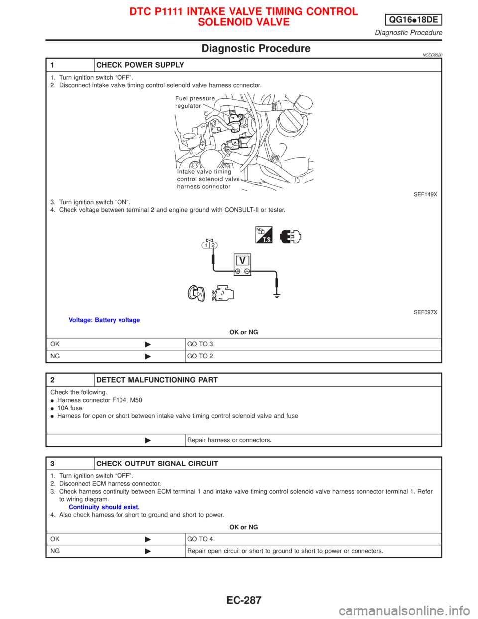
1 CHECK POWER SUPPLY
1. Turn ignition switch ªOFFº.
2. Disconnect intake valve timing control solenoid valve harness connector.
SEF149X3. Turn ignition switch ªONº.
4. Check voltage between terminal 2 and engine ground with CONSULT-II or tester.
SEF097XVoltage: Battery voltage
OK or NG
OK©GO TO 3.
NG©GO TO 2.
2 DETECT MALFUNCTIONING PART
Check the following.
IHarness connector F104, M50
I10A fuse
IHarness for open or short between intake valve timing control solenoid valve and fuse
©Repair harness or connectors.
3 CHECK OUTPUT SIGNAL CIRCUIT
1. Turn ignition switch ªOFFº.
2. Disconnect ECM harness connector.
3. Check harness continuity between ECM terminal 1 and intake valve timing control solenoid valve harness connector terminal 1. Refer
to wiring diagram.
Continuity should exist.
4. Also check harness for short to ground and short to power.
OK or NG
OK©GO TO 4.
NG©Repair open circuit or short to ground to short to power or connectors.
D T C P 1111 I N TA K E VA LV ETIMING CONTROL
SOLENOID VALVEQG16I18DE
Diagnostic Procedure
EC-287
Page 730 of 2267
4 CHECK VALVE TIMING CONTROL SOLENOID VALVE
Refer to ªComponent Inspectionº, EC-QG-288.
OK or NG
OK©GO TO 5.
NG©Replace valve timing control solenoid valve.
5 CHECK INTERMITTENT INCIDENT
Perform ªTROUBLE DIAGNOSIS FOR INTERMITTENT INCIDENTº, EC-QG-102.
©INSPECTION END
Component InspectionNCEC0521INTAKE VALVE TIMING CONTROL SOLENOID VALVENCEC0521S011. Check oil passage visually for any metal debris.
2. Supply intake valve timing control solenoid valve terminals with
battery voltage.
3. Make sure that inside plunger protrudes.
If NG, replace intake valve timing control solenoid valve.
SEF524T Intake valve timing
control solenoid valve
Plunger
FUSE
D T C P 1111 I N TA K E VA LV ETIMING CONTROL
SOLENOID VALVEQG16I18DE
Diagnostic Procedure (Cont'd)
EC-288
Page 734 of 2267
Wiring DiagramNCEC0490
YEC789
: Detectable line for DTC
: Non-detectable line for DTC
COOLING
FA N
RELAY FUSE
BLOCK
(J/B)
COOLING
FA N
MOTOR-2 Refer to EL-POWER. BATTERY
COOLING
FA N
MOTOR-1 IGNITION SWITCH
ON or START
Refer to last page (Foldout page)
DTC P1217 OVERHEAT (COOLING SYSTEM)QG16I18DE
Wiring Diagram
EC-292
Page 737 of 2267

4 DETECT MALFUNCTIONING PART
Check the following.
IHarness connectors M70, E125
I10A fuse
I40A fusible link
IHarness for open or short between cooling fan relay and fuse
IHarness for open or short between cooling fan relay and battery
©Repair open circuit or short to ground or short to power in harness or connectors.
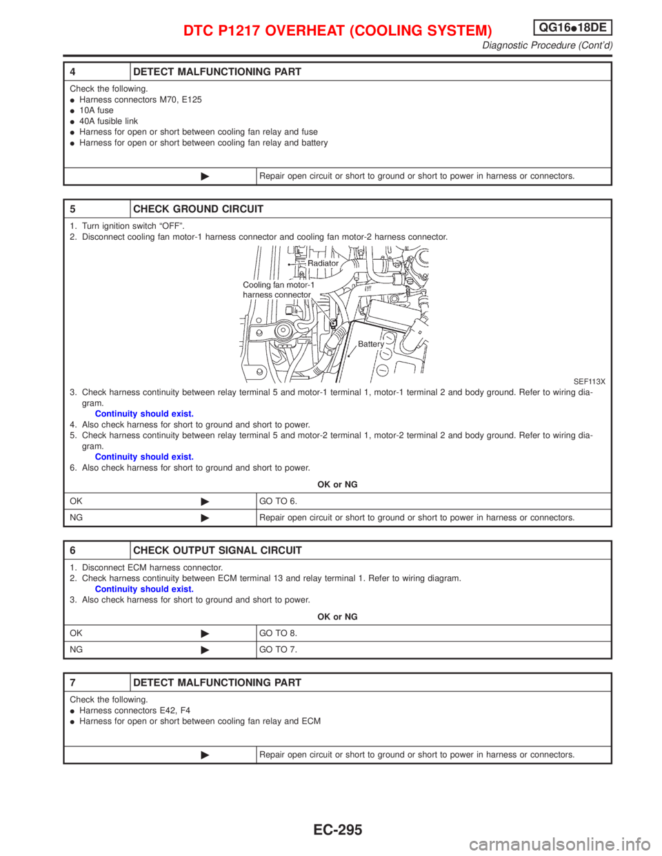
5 CHECK GROUND CIRCUIT
1. Turn ignition switch ªOFFº.
2. Disconnect cooling fan motor-1 harness connector and cooling fan motor-2 harness connector.
SEF113X3. Check harness continuity between relay terminal 5 and motor-1 terminal 1, motor-1 terminal 2 and body ground. Refer to wiring dia-
gram.
Continuity should exist.
4. Also check harness for short to ground and short to power.
5. Check harness continuity between relay terminal 5 and motor-2 terminal 1, motor-2 terminal 2 and body ground. Refer to wiring dia-
gram.
Continuity should exist.
6. Also check harness for short to ground and short to power.
OK or NG
OK©GO TO 6.
NG©Repair open circuit or short to ground or short to power in harness or connectors.
6 CHECK OUTPUT SIGNAL CIRCUIT
1. Disconnect ECM harness connector.
2. Check harness continuity between ECM terminal 13 and relay terminal 1. Refer to wiring diagram.
Continuity should exist.
3. Also check harness for short to ground and short to power.
OK or NG
OK©GO TO 8.
NG©GO TO 7.
7 DETECT MALFUNCTIONING PART
Check the following.
IHarness connectors E42, F4
IHarness for open or short between cooling fan relay and ECM
©Repair open circuit or short to ground or short to power in harness or connectors.
DTC P1217 OVERHEAT (COOLING SYSTEM)QG16I18DE
Diagnostic Procedure (Cont'd)
EC-295
Page 761 of 2267
Wiring DiagramNCEC0434
YEC792
IGNITION SWITCH
ON or START
Refer to
EL-POWER.: Detectable line for DTC
: Non-detectable line for DTC
FUSE
BLOCK
(J/B)
ECM
Refer to last page (Foldout page) INJECTOR
No.1INJECTOR
No.2INJECTOR
No.3INJECTOR
No.4
INJECTORQG16I18DE
Wiring Diagram
EC-319
Page 763 of 2267

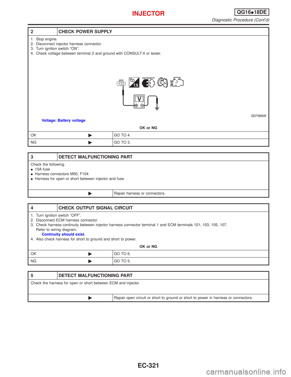
2 CHECK POWER SUPPLY
1. Stop engine.
2. Disconnect injector harness connector.
3. Turn ignition switch ªONº.
4. Check voltage between terminal 2 and ground with CONSULT-II or tester.
SEF986WVoltage: Battery voltage
OK or NG
OK©GO TO 4.
NG©GO TO 3.
3 DETECT MALFUNCTIONING PART
Check the following.
I10A fuse
IHarness connectors M50, F104
IHarness for open or short between injector and fuse
©Repair harness or connectors.
4 CHECK OUTPUT SIGNAL CIRCUIT
1. Turn ignition switch ªOFFº.
2. Disconnect ECM harness connector.
3. Check harness continuity between injector harness connector terminal 1 and ECM terminals 101, 103, 105, 107.
Refer to wiring diagram.
Continuity should exist.
4. Also check harness for short to ground and short to power.
OK or NG
OK©GO TO 6.
NG©GO TO 5.
5 DETECT MALFUNCTIONING PART
Check the harness for open or short between ECM and injector.
©Repair open circuit or short to ground or short to power in harness or connectors.
INJECTORQG16I18DE
Diagnostic Procedure (Cont'd)
EC-321
Page 770 of 2267
6 CHECK IGNITION COIL POWER SUPPLY CIRCUIT-III
1. Turn ignition switch OFF.
2. Disconnect ECM relay.
SEF984W3. Check harness continuity between ECM relay terminal 7 and condenser terminal 1. Refer to wiring diagram.
Continuity should exist.
4. Also check harness for short to ground and short to power.
OK or NG
OK©GO TO 8.
NG©GO TO 7.
7 DETECT MALFUNCTIONING PART
Check the following.
IHarness connectors F73, E90
IHarness for open or short between ECM relay and condenser
©Repair open circuit or short to ground or short to power in harness or connectors.
8 CHECK IGNITION COIL POWER SUPPLY CIRCUIT-IV
1. Check voltage between ECM relay terminal 6 and ground with CONSULT-II or tester.
SEF368X
OK or NG
OK©GO TO 10.
NG©GO TO 9.
9 DETECT MALFUNCTIONING PART
Check the following.
I15A fuses
IHarness for open and short between ECM relay and fuse
©Repair or replace harness or connectors.
IGNITION SIGNALQG16I18DE
Diagnostic Procedure (Cont'd)
EC-328
Page 775 of 2267
Wiring DiagramNCEC0440
YEC282
BATTERY
Refer to EL-POWER.
: Detectable line for DTC
: Non-detectable line for DTC
FUSE
BLOCK
(J/B) IGNITION
SWITCH
REFER TO THE FOLLOWING
FUSE BLOCK - Junction Box (J/B)
FUSE BLOCK - Junction Box (J/B) OFF
ACC
ONST
START SIGNALQG16I18DE
Wiring Diagram
EC-333