Page 917 of 2267
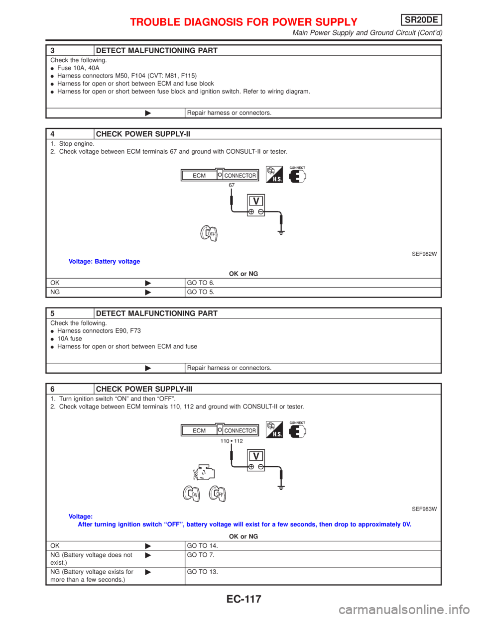
3 DETECT MALFUNCTIONING PART
Check the following.
IFuse 10A, 40A
IHarness connectors M50, F104 (CVT: M81, F115)
IHarness for open or short between ECM and fuse block
IHarness for open or short between fuse block and ignition switch. Refer to wiring diagram.
©Repair harness or connectors.
4 CHECK POWER SUPPLY-II
1. Stop engine.
2. Check voltage between ECM terminals 67 and ground with CONSULT-II or tester.
SEF982WVoltage: Battery voltage
OK or NG
OK©GO TO 6.
NG©GO TO 5.
5 DETECT MALFUNCTIONING PART
Check the following.
IHarness connectors E90, F73
I10A fuse
IHarness for open or short between ECM and fuse
©Repair harness or connectors.
6 CHECK POWER SUPPLY-III
1. Turn ignition switch ªONº and then ªOFFº.
2. Check voltage between ECM terminals 110, 112 and ground with CONSULT-II or tester.
SEF983WVoltage:
After turning ignition switch ªOFFº, battery voltage will exist for a few seconds, then drop to approximately 0V.
OK or NG
OK©GO TO 14.
NG (Battery voltage does not
exist.)©GO TO 7.
NG (Battery voltage exists for
more than a few seconds.)©GO TO 13.
TROUBLE DIAGNOSIS FOR POWER SUPPLYSR20DE
Main Power Supply and Ground Circuit (Cont'd)
EC-117
Page 918 of 2267
7 CHECK HARNESS CONTINUITY BETWEEN ECM RELAY AND ECM
1. Disconnect ECM harness connector.
2. Disconnect ECM relay.
SEF984W3. Check harness continuity between ECM terminals 110, 112 and relay terminal 5.
Refer to wiring diagram.
Continuity should exist.
4. Also check harness for short to ground and short to power.
OK or NG
OK©GO TO 9.
NG©GO TO 8.
8 DETECT MALFUNCTIONING PART
Check the following.
IHarness connectors E90, F73
IHarness for open or short between ECM relay and ECM
©Repair open circuit or short to ground or short to power in harness or connectors.
9 CHECK VOLTAGE BETWEEN ECM RELAY AND GROUND
Check voltage between relay terminals 1, 3 and ground with CONSULT-II or tester.
SEF985WVoltage: Battery voltage
OK or NG
OK©GO TO 11.
NG©GO TO 10.
10 DETECT MALFUNCTIONING PART
Check the harness for open or short between ECM relay and fuse.
©Repair harness or connectors.
TROUBLE DIAGNOSIS FOR POWER SUPPLYSR20DE
Main Power Supply and Ground Circuit (Cont'd)
EC-118
Page 978 of 2267
Diagnostic ProcedureNCEC0142
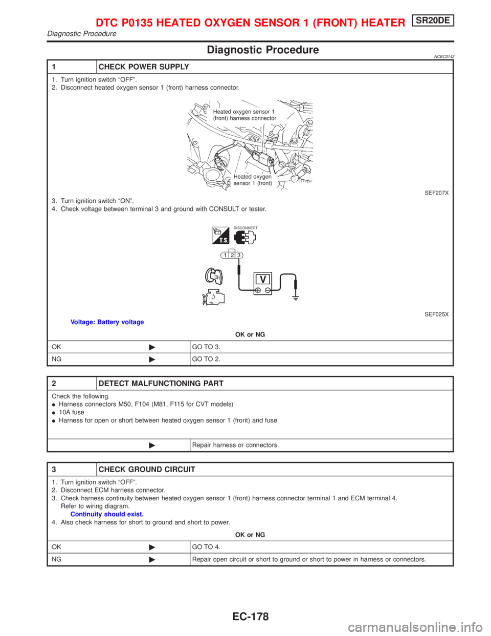
1 CHECK POWER SUPPLY
1. Turn ignition switch ªOFFº.
2. Disconnect heated oxygen sensor 1 (front) harness connector.
SEF207X3. Turn ignition switch ªONº.
4. Check voltage between terminal 3 and ground with CONSULT or tester.
SEF025XVoltage: Battery voltage
OK or NG
OK©GO TO 3.
NG©GO TO 2.
2 DETECT MALFUNCTIONING PART
Check the following.
IHarness connectors M50, F104 (M81, F115 for CVT models)
I10A fuse
IHarness for open or short between heated oxygen sensor 1 (front) and fuse
©Repair harness or connectors.
3 CHECK GROUND CIRCUIT
1. Turn ignition switch ªOFFº.
2. Disconnect ECM harness connector.
3. Check harness continuity between heated oxygen sensor 1 (front) harness connector terminal 1 and ECM terminal 4.
Refer to wiring diagram.
Continuity should exist.
4. Also check harness for short to ground and short to power.
OK or NG
OK©GO TO 4.
NG©Repair open circuit or short to ground or short to power in harness or connectors.
Heated oxygen sensor 1
(front) harness connector
Heated oxygen
sensor 1 (front)
DISCONNECT
DTC P0135 HEATED OXYGEN SENSOR 1 (FRONT) HEATERSR20DE
Diagnostic Procedure
EC-178
Page 1010 of 2267
Diagnostic ProcedureNCEC0186
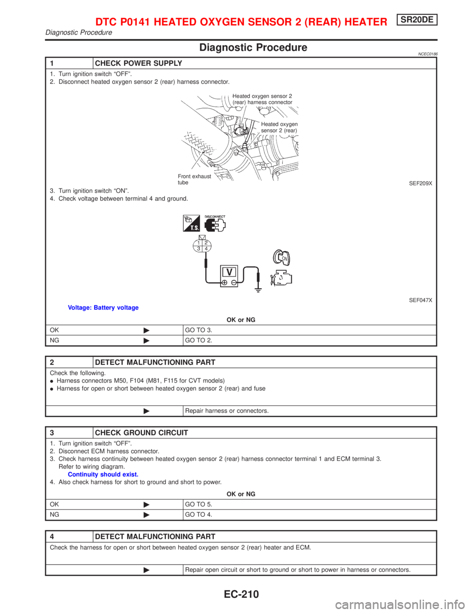
1 CHECK POWER SUPPLY
1. Turn ignition switch ªOFFº.
2. Disconnect heated oxygen sensor 2 (rear) harness connector.
SEF209X3. Turn ignition switch ªONº.
4. Check voltage between terminal 4 and ground.
SEF047XVoltage: Battery voltage
OK or NG
OK©GO TO 3.
NG©GO TO 2.
2 DETECT MALFUNCTIONING PART
Check the following.
IHarness connectors M50, F104 (M81, F115 for CVT models)
IHarness for open or short between heated oxygen sensor 2 (rear) and fuse
©Repair harness or connectors.
3 CHECK GROUND CIRCUIT
1. Turn ignition switch ªOFFº.
2. Disconnect ECM harness connector.
3. Check harness continuity between heated oxygen sensor 2 (rear) harness connector terminal 1 and ECM terminal 3.
Refer to wiring diagram.
Continuity should exist.
4. Also check harness for short to ground and short to power.
OK or NG
OK©GO TO 5.
NG©GO TO 4.
4 DETECT MALFUNCTIONING PART
Check the harness for open or short between heated oxygen sensor 2 (rear) heater and ECM.
©Repair open circuit or short to ground or short to power in harness or connectors.
Heated oxygen sensor 2
(rear) harness connector
Heated oxygen
sensor 2 (rear)
Front exhaust
tube
DTC P0141 HEATED OXYGEN SENSOR 2 (REAR) HEATERSR20DE
Diagnostic Procedure
EC-210
Page 1052 of 2267
Wiring DiagramNCEC0253
YEC843
IGNITION SWITCH
ON or START
Refer to EL-POWER.: Detectable line for DTC
: Non-detectable line for DTC
: Hyper CVT models
: M/T models FUSE
BLOCK
(J/B)
EVAP
CANISTER
PURGE
CONTROL
SOLENOID
VA LV E
.ECM
REFER TO THE FOLLOWING
FUSE BLOCK -
Junction Box (J/B)
DTC P0443 EVAP CANISTER PURGE VOLUME CONTROL
SOLENOID VALVE (CIRCUIT)SR20DE
Wiring Diagram
EC-252
Page 1057 of 2267
Wiring DiagramNCEC0277MODELS BEFORE VIN - P11U0548750
YEC844
IGNITION SWITCH
ON or START
Refer to EL-POWER.: Detectable line for DTC
: Non-detectable line for DTC
: Hyper CVT models
: M/T models FUSE
BLOCK
(J/B)
COMBINATION
METER
(SPEEDOMETER)
ECM
REFER TO THE FOLLOWING
FUSE BLOCK -
Junction Box (J/B) VEHICLE
SPEED
SENSOR BATTERY
DTC P0500 VEHICLE SPEED SENSOR (VSS)SR20DE
Wiring Diagram
EC-257
Page 1066 of 2267
Diagnostic ProcedureNCEC0285
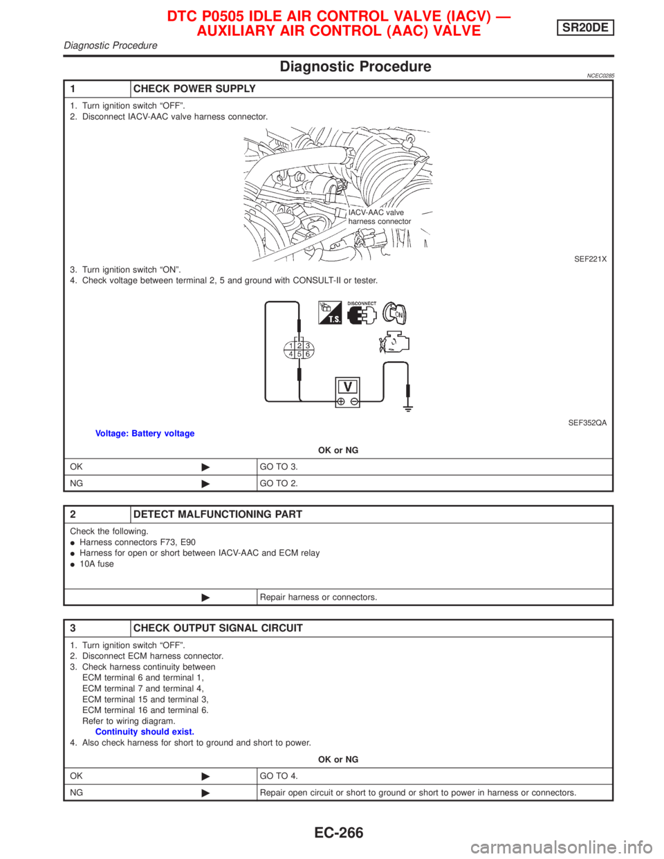
1 CHECK POWER SUPPLY
1. Turn ignition switch ªOFFº.
2. Disconnect IACV-AAC valve harness connector.
SEF221X3. Turn ignition switch ªONº.
4. Check voltage between terminal 2, 5 and ground with CONSULT-II or tester.
SEF352QAVoltage: Battery voltage
OK or NG
OK©GO TO 3.
NG©GO TO 2.
2 DETECT MALFUNCTIONING PART
Check the following.
IHarness connectors F73, E90
IHarness for open or short between IACV-AAC and ECM relay
I10A fuse
©Repair harness or connectors.
3 CHECK OUTPUT SIGNAL CIRCUIT
1. Turn ignition switch ªOFFº.
2. Disconnect ECM harness connector.
3. Check harness continuity between
ECM terminal 6 and terminal 1,
ECM terminal 7 and terminal 4,
ECM terminal 15 and terminal 3,
ECM terminal 16 and terminal 6.
Refer to wiring diagram.
Continuity should exist.
4. Also check harness for short to ground and short to power.
OK or NG
OK©GO TO 4.
NG©Repair open circuit or short to ground or short to power in harness or connectors.
IACV-AAC valve
harness connector
DTC P0505 IDLE AIR CONTROL VALVE (IACV) Ð
AUXILIARY AIR CONTROL (AAC) VALVESR20DE
Diagnostic Procedure
EC-266
Page 1074 of 2267
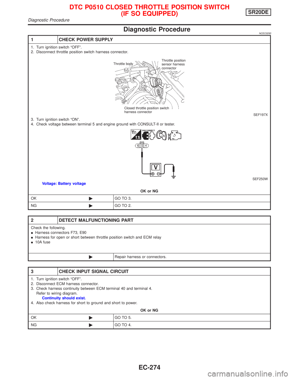
Diagnostic ProcedureNCEC0293
1 CHECK POWER SUPPLY
1. Turn ignition switch ªOFFº.
2. Disconnect throttle position switch harness connector.
SEF197X3. Turn ignition switch ªONº.
4. Check voltage between terminal 5 and engine ground with CONSULT-II or tester.
SEF250WVoltage: Battery voltage
OK or NG
OK©GO TO 3.
NG©GO TO 2.
2 DETECT MALFUNCTIONING PART
Check the following.
IHarness connectors F73, E90
IHarness for open or short between throttle position switch and ECM relay
I10A fuse
©Repair harness or connectors.
3 CHECK INPUT SIGNAL CIRCUIT
1. Turn ignition switch ªOFFº.
2. Disconnect ECM harness connector.
3. Check harness continuity between ECM terminal 40 and terminal 4.
Refer to wiring diagram.
Continuity should exist.
4. Also check harness for short to ground and short to power.
OK or NG
OK©GO TO 5.
NG©GO TO 4.
Throttle bodyThrottle position
sensor harness
connector
Closed throttle position switch
harness connector
DTC P0510 CLOSED THROTTLE POSITION SWITCH
(IF SO EQUIPPED)SR20DE
Diagnostic Procedure
EC-274