Page 1082 of 2267
Wiring DiagramNCEC0490
YEC847
Detectable line for DTC
Non-detectable line for DTC
COOLING
FA N
RELAY FUSE
BLOCK
(J/B)
COOLING
FA N
MOTOR-2 Refer to EL-POWER. BATTERY
COOLING
FA N
MOTOR-1 IGNITION SWITCH
ON or START
REFER TO THE FOLLOWING
FUSE BLOCK -
Junction Box (J/B)
DTC P1217 OVERHEAT (COOLING SYSTEM)SR20DE
Wiring Diagram
EC-282
Page 1085 of 2267

4 DETECT MALFUNCTIONING PART
Check the following.
IHarness connectors M70, E125
I10A fuse
I40A fusible link
IHarness for open or short between cooling fan relay and fuse
©Repair open circuit or short to ground or short to power in harness or connectors.
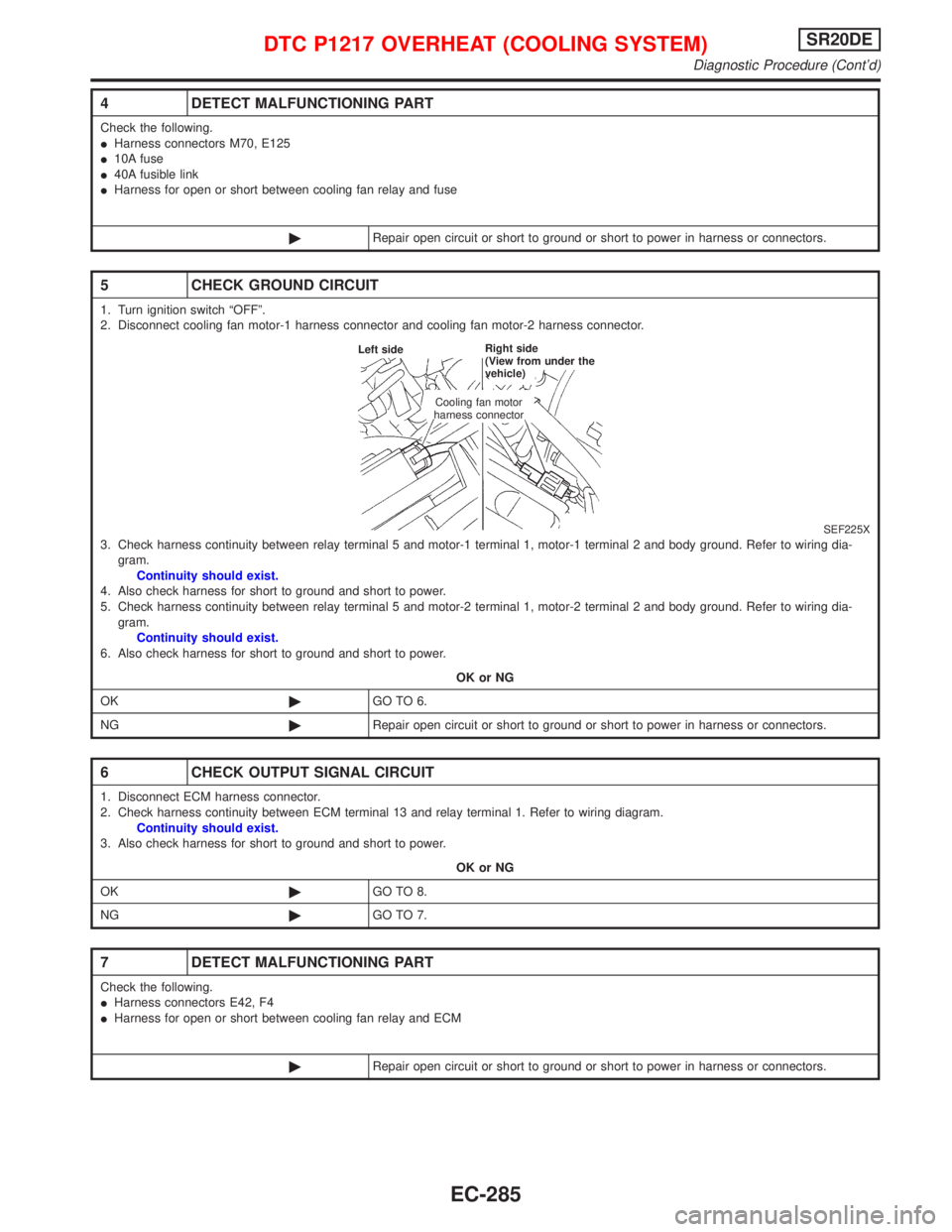
5 CHECK GROUND CIRCUIT
1. Turn ignition switch ªOFFº.
2. Disconnect cooling fan motor-1 harness connector and cooling fan motor-2 harness connector.
SEF225X3. Check harness continuity between relay terminal 5 and motor-1 terminal 1, motor-1 terminal 2 and body ground. Refer to wiring dia-
gram.
Continuity should exist.
4. Also check harness for short to ground and short to power.
5. Check harness continuity between relay terminal 5 and motor-2 terminal 1, motor-2 terminal 2 and body ground. Refer to wiring dia-
gram.
Continuity should exist.
6. Also check harness for short to ground and short to power.
OK or NG
OK©GO TO 6.
NG©Repair open circuit or short to ground or short to power in harness or connectors.
6 CHECK OUTPUT SIGNAL CIRCUIT
1. Disconnect ECM harness connector.
2. Check harness continuity between ECM terminal 13 and relay terminal 1. Refer to wiring diagram.
Continuity should exist.
3. Also check harness for short to ground and short to power.
OK or NG
OK©GO TO 8.
NG©GO TO 7.
7 DETECT MALFUNCTIONING PART
Check the following.
IHarness connectors E42, F4
IHarness for open or short between cooling fan relay and ECM
©Repair open circuit or short to ground or short to power in harness or connectors.
Cooling fan motor
harness connector Left sideRight side
(View from under the
vehicle)
DTC P1217 OVERHEAT (COOLING SYSTEM)SR20DE
Diagnostic Procedure (Cont'd)
EC-285
Page 1103 of 2267
Wiring DiagramNCEC0434
YEC251
IGNITION SWITCH
ON or START
Refer to
EL-POWER.Detectable line for DTC
Non-detectable line for DTC
Hyper CVT models
M/T models FUSE
BLOCK
(J/B)
INJECTOR
No.4
ECM
REFER TO THE FOLLOWING
FUSE BLOCK -
Junction Box (J/B) INJECTOR
No.1INJECTOR
No.2INJECTOR
No.3
INJECTORSR20DE
Wiring Diagram
EC-303
Page 1105 of 2267
![NISSAN PRIMERA 1999 Electronic Repair Manual Component InspectionNCEC0439INJECTORNCEC0439S011. Disconnect injector harness connector.
2. Check resistance between terminals as shown in the figure.
Resistance: 13.5 - 17.5W[at 25ÉC (77ÉF)]
If NG, NISSAN PRIMERA 1999 Electronic Repair Manual Component InspectionNCEC0439INJECTORNCEC0439S011. Disconnect injector harness connector.
2. Check resistance between terminals as shown in the figure.
Resistance: 13.5 - 17.5W[at 25ÉC (77ÉF)]
If NG,](/manual-img/5/57377/w960_57377-1104.png)
Component InspectionNCEC0439INJECTORNCEC0439S011. Disconnect injector harness connector.
2. Check resistance between terminals as shown in the figure.
Resistance: 13.5 - 17.5W[at 25ÉC (77ÉF)]
If NG, replace injector.
3 DETECT MALFUNCTIONING PART
Check the following.
I10A fuse
IHarness connectors F13, F60
IHarness connectors M50, F104 (CVT: M81, F115)
IHarness for open or short between injector and fuse
©Repair harness or connectors.
4 CHECK OUTPUT SIGNAL CIRCUIT
1. Turn ignition switch ªOFFº.
2. Disconnect ECM harness connector.
3. Check harness continuity between injector harness connector terminal 1 and ECM terminals 101, 103, 105, 107.
Refer to wiring diagram.
Continuity should exist.
4. Also check harness for short to ground and short to power.
OK or NG
OK©GO TO 6.
NG©GO TO 5.
5 DETECT MALFUNCTIONING PART
Check the following.
IHarness connectors F13, F60
IHarness for open or short between ECM and injector
©Repair open circuit or short to ground or short to power in harness or connectors.
6 CHECK INJECTOR
Refer to ªComponent Inspectionº, EC-SR-305.
OK or NG
OK©GO TO 7.
NG©Replace injector.
7 CHECK INTERMITTENT INCIDENT
Perform ªTROUBLE DIAGNOSIS FOR INTERMITTENT INCIDENTº, EC-SR-114.
©INSPECTION END
SEF139X
INJECTORSR20DE
Component Inspection
EC-305
Page 1113 of 2267
Wiring DiagramNCEC0440
YEC252
BATTERY
Refer to EL-POWER.
Detectable line for DTC
Non-detectable line for DTC
Hyper CVT models
M/T models
FUSE
BLOCK
(J/B) IGNITION
SWITCH
ECM
.REFER TO THE FOLLOWING
M1FUSE BLOCK -
Junction Box (J/B)
E104FUSE BLOCK -
Junction Box (J/B)
OFF
ACC
ONST
START SIGNALSR20DE
Wiring Diagram
EC-313
Page 1115 of 2267
4 DETECT MALFUNCTIONING PART
Check the following.
IHarness connectors M50, F104 (CVT: M81, F115)
I10A fuse
IHarness for open or short between ECM and ignition switch
OK or NG
OK©GO TO 5.
NG©Repair open circuit or short to ground or short to power in harness or connectors.
5 CHECK INTERMITTENT INCIDENT
Perform ªTROUBLE DIAGNOSIS FOR INTERMITTENT INCIDENTº, EC-SR-114.
©INSPECTION END
START SIGNALSR20DE
Diagnostic Procedure (Cont'd)
EC-315
Page 1117 of 2267
Wiring DiagramNCEC0447
YEC253
IGNITION SWITCH
ON or START
Refer to EL-POWER.
Detectable line for DTC
Non-detectable line for DTC
Hyper CVT models
M/T models FUSE
BLOCK
(J/B)
ECM
.REFER TO THE FOLLOWING
M1FUSE BLOCK -
Junction Box (J/B)
B8FUSE BLOCK -
Junction Box (J/B)
FUEL
PUMP
RELAY
FUEL PUMP
FUEL PUMPSR20DE
Wiring Diagram
EC-317
Page 1118 of 2267
Diagnostic ProcedureNCEC0448
1 CHECK OVERALL FUNCTION
1. Turn ignition switch ªONº.
2. Pinch fuel feed hose with fingers.
SEF241XFuel pressure pulsation should be felt on the fuel feed hose for 1 second after ignition switch is turned ªONº.
OK or NG
OK©INSPECTION END
NG©GO TO 2.
2 CHECK POWER SUPPLY
1. Turn ignition switch ªOFFº.
2. Disconnect fuel pump relay located on the fuse block.
SEF071X3. Turn ignition switch ªONº.
4. Check voltage between terminals 1, 3 and ground with CONSULT-II or tester.
SEF144XVoltage: Battery voltage
OK or NG
OK©GO TO 4.
NG©GO TO 3.
Fuel filter
Pinch
FUEL PUMPSR20DE
Diagnostic Procedure
EC-318