Page 1287 of 2267
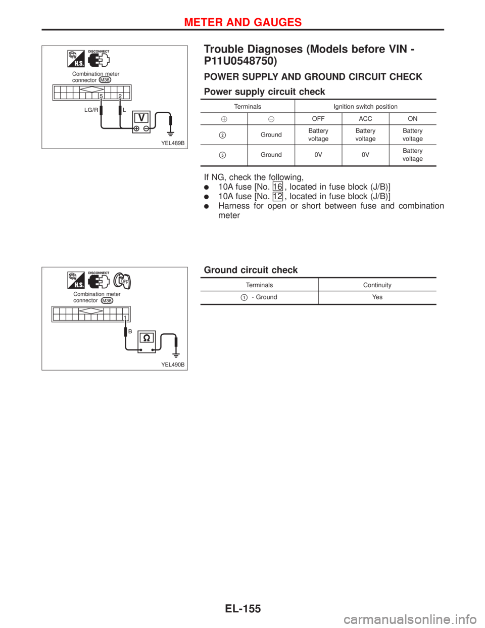
Trouble Diagnoses (Models before VIN -
P11U0548750)
POWER SUPPLY AND GROUND CIRCUIT CHECK
Power supply circuit check
Terminals Ignition switch position
��OFF ACC ON
�2GroundBattery
voltageBattery
voltageBattery
voltage
�5Ground 0V 0VBattery
voltage
If NG, check the following,
�10A fuse [No.16 , located in fuse block (J/B)]
�10A fuse [No.12 , located in fuse block (J/B)]
�Harness for open or short between fuse and combination
meter
Ground circuit check
Terminals Continuity
�1- Ground Yes
YEL489B Combination meter
connector
YEL490B Combination meter
connector
METER AND GAUGES
EL-155
Page 1291 of 2267
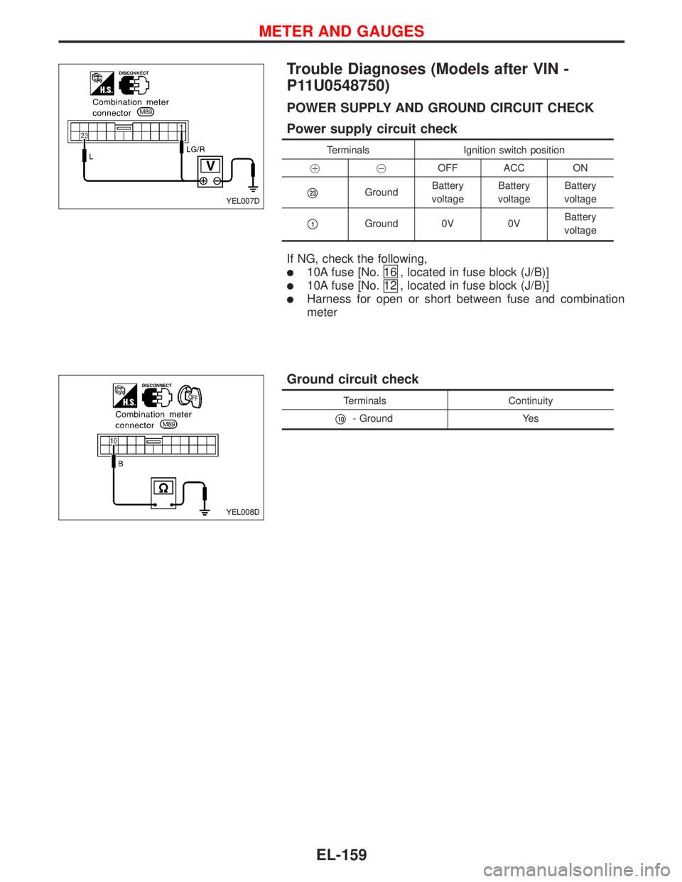
Trouble Diagnoses (Models after VIN -
P11U0548750)
POWER SUPPLY AND GROUND CIRCUIT CHECK
Power supply circuit check
Terminals Ignition switch position
��OFF ACC ON
�23GroundBattery
voltageBattery
voltageBattery
voltage
�1Ground 0V 0VBattery
voltage
If NG, check the following,
�10A fuse [No.16 , located in fuse block (J/B)]
�10A fuse [No.12 , located in fuse block (J/B)]
�Harness for open or short between fuse and combination
meter
Ground circuit check
Terminals Continuity
�10- Ground Yes
YEL007D
YEL008D
METER AND GAUGES
EL-159
Page 1297 of 2267
Warning Lamps/Schematic
MODELS BEFORE VIN - P11U0548750
YEL167C
GLOW
MALFUNCTION INDICA-
TOR LAMP
ABS
BRAKE
WASH
DOOR
CHARGE
OIL
FUELElectronic
speedometer
module
COMBINATION METER
IGNITION SWITCH
ON or START
FUSE
AIR BAG: M/T models
: CVT models
:H⋅CVT models
:H⋅CVT (M6) models
: With GA engine
: With SR engine or QG engine
: With diesel engine
TIME CON-
TROL UNIT
DIAGNOSIS
SENSOR
UNITFUEL
LEVEL
SENSOR
UNITOIL PRES-
SURE
SWITCHALTER-
NATORFRONT
DOOR
SWITCH
(DRIVER
SIDE)FRONT
DOOR
SWITCH
(PASSEN-
GER SIDE)REAR
DOOR
SWITCH
LHREAR
DOOR
SWITCH
RHWASHER
LEVEL
SWITCHBRAKE
FLUID
LEVEL
SWITCHPARKING
BRAKE
SWITCH
VACUUM
SWITCHSEDIMENTER
SENSOR
ABS
ACTUATOR
AND ELEC-
TRIC UNIT
(CONTROL
UNIT)TCM (TRANS-
MISSION CON-
TROL MODULE)
CVT WARNING LAMP
SPORT INDICATOR LAMP
TRUNK ROOM
LAMP SWITCH
OR
LUGGAGE
ROOM LAMP
SWITCH
ECM
WARNING LAMPS
EL-165
Page 1299 of 2267
Wiring Diagram—WARN—
MODELS BEFORE VIN - P11U0548750
YEL168C
IGNITION SWITCH
ON or START
FUSE BLOCK
(J/B)Refer to EL-POWER.: CVT models
: M/T models
AIR BAGFUEL
ELECTRONIC
SPEEDOMETER
MODULEOILCOMBINATION
METER
FUEL LEVEL SEN-
SOR UNIT
DIAGNOSIS
SENSOR
UNITLOWHIGHOIL PRES-
SURE SWITCH
REFER TO THE FOLLOWING
FUSE BLOCK - Junction Box (J/B)Next
page
To
EL-WARN-06
FUSE BLOCK
(J/B)
WARNING LAMPS
EL-167
Page 1301 of 2267
YEL169C
Preceding
pageTo
EL-WARN-05
DOORCOMBINATION
METER
Next page
FUSE
BLOCK
(J/B)
FRONT DOOR
SWITCH (PAS-
SENGER SIDE)
CLOSEDOPEN
FRONT DOOR
SWITCH
(DRIVER SIDE) OPEN
CLOSEDREAR DOOR
SWITCH LH
OPEN
CLOSEDREAR DOOR
SWITCH RH
OPEN
CLOSED
REFER TO THE FOLLOWING
FUSE BLOCK - Junction Box (J/B) TIME
CON-
TROL
UNIT
*: This connector is not shown in“HARNESS LAYOUT”of el section.
WARNING LAMPS
Wiring Diagram—WARN—(Cont’d)
EL-169
Page 1316 of 2267

CHECK LIGHTING SWITCH INPUT
SIGNAL.
Check voltage between control unit
terminal
�10and ground.
OK
�NG
Check the following.
�15A fuse (No.34,")
DIAGNOSTIC PROCEDURE 1
(Lighting switch input signal check)
CHECK LIGHTING SWITCH INPUT
SIGNAL.
Check voltage between control unit
terminal
�10and ground.
OK
�NG
Check the following.
�15A fuse (No.34,
located in the fuse and
fusible link box)
�Harness for open or
short between control
unit and lighting switch
Go to Procedure 3.
Condition of lighting
switchVoltage [V]
1ST or 2ND Approx. 12
OFF 0
DIAGNOSTIC PROCEDURE 2
(Key switch input signal check)
CHECK KEY SWITCH INPUT SIGNAL.
Check voltage between control unit
terminal
�22and ground.
OK
�NG
Check the following.
�Key switch
Refer to“Electrical
Components Inspec-
tion”(EL-185).
�10A fuse [No.16,
located in fuse block
(J/B)]
�Harness for open or
short between key
switch and fuse
�Harness for open or
short between control
unit and key switch
Go to Procedure 3.
Condition of key switch Voltage [V]
Key is inserted. Approx. 12
Key is withdrawn. 0
YEL432B
Time control
unit connector
YEL433B
Time control
unit connector
: Approx.
12V
:0V
�
�
WARNING CHIME
Trouble Diagnoses (Cont’d)
EL-184
Page 1317 of 2267

terminal
16Jand ground.
OK
�NG
Check the following.
�Driver side door switch
Refer to“Electrical
Compo")
DIAGNOSTIC PROCEDURE 3
CHECK DOOR SWITCH INPUT SIG-
NAL.
Check voltage between fuse block (J/B)
terminal
16Jand ground.
OK
�NG
Check the following.
�Driver side door switch
Refer to“Electrical
Components Inspec-
tion”(EL-185).
�Door switch ground
circuit
�Harness for open or
short between control
unit and door switch
Check continuity between fuse block
(J/B) terminal
16Jand control unit ter-
minal
�6.
Continuity should exist.
OK
�NG
Replace fuse block (J/B).
Replace time control unit.
Condition of driver’s door Voltage [V]
Driver side door is closed. Approx. 12
Driver side door is open. 0
Electrical Components Inspection
KEY SWITCH (insert)
Check continuity between terminals when key is inserted in igni-
tion key cylinder and key is removed from ignition key cylinder.
Terminal No. Condition Continuity
�1-�2Key is inserted. Yes
Key is removed. No
DRIVER SIDE DOOR SWITCH
Check continuity between terminals when door switch is pushed
and released.
Terminal No. Condition Continuity
�2-�3(Type-1) or
�1- Ground (Type-2)Door switch is pushed. No
Door switch is
released.Ye s
YEL434B Fuse block (J/B) connector
YEL435B
Time control unit
connectorFuse block (J/B)
connector
YEL436B Key switch connector
YEL026D
YEL025D
�
�
WARNING CHIME
Trouble Diagnoses (Cont’d)
EL-185
Page 1318 of 2267
.
With th")
System Description
WIPER OPERATION
The wiper switch is controlled by a lever built into the combination switch.
There are three wiper switch positions:
�LO speed
�HI speed
�INT (Intermittent).
With the ignition switch in the ON or START position, power is supplied
�through 20A fuse (No.located in the fuse block)
�to wiper motor terminal�6and�3.
Low and high speed wiper operation
Ground is supplied to wiper switch terminal�17through body groundsE11andE37.
When the wiper switch is placed in the LO position, ground is supplied
�Through terminal�14of the wiper switch
�to wiper motor terminal�2.
With power and ground supplied, the wiper motor operates at low speed.
When the wiper switch is placed in the HI position, ground is supplied
�Through terminal�16of the wiper switch
�to wiper motor terminal�1.
With power and ground supplied, the wiper motor operates at high speed.
Auto stop operation
With wiper switch turned OFF, wiper motor will continue to operate until wiper arms reach windshield base.
When wiper arms are not located at base of windshield with wiper switch OFF, ground is provided
�from terminal�14of the wiper switch
�to wiper motor terminal�2, in order to continue wiper motor operation at low speed.
Ground is also supplied
�through terminal�13of the wiper switch
�to front wiper relay terminal�3
�through terminal�4of the front wiper relay
�to wiper motor terminal�5
�through terminal�4of the wiper motor, and
�through body groundsE11andE37.
When wiper arms reach base of windshield, wiper motor terminals
�5and�3are connected instead of
terminals
�5and�4. Wiper motor will then stop wiper arms at the PARK position.
Intermittent operation
With variable intermittent
The wiper motor operates the wiper arms at a set interval of approximately 2 to 20 seconds. This feature is
controlled by the combination switch wiper amplifier.
When the wiper switch is placed in the INT position, ground is supplied
�to front wiper relay terminal�5
�from wiper switch terminal�13
�through body groundsE37andE11.
�to wiper motor terminal�2
�through the wiper switch terminal�14
�to wiper switch terminal�13
�through front wiper relay terminal�3
The desired interval time is input
�to front wiper relay terminal�1
�from wiper switch terminal�20.
The wiper motor operates at low speed at the desired time interval.
FRONT WIPER AND WASHER
EL-186

Refer to EL-POWER.: CVT models
: M/T models
AIR BAGFUEL
ELECTRONIC
SPEEDOMETER
MODULEOILCOM")

FRONT DOOR
SWITCH (PAS-
SENGER SIDE)
CLOSEDOPEN
FRONT DOOR
SWITCH
(DRIVER SIDE) OPEN
CLOSEDREAR DOOR
SWITCH LH
OPEN")