Page 1340 of 2267
Schematic
YEL182C
REAR WIN-
DOW DEFOG-
GER SWITCH : With door mirror heater
FUSEFUSE
REAR WINDOW
DEFOGGER
CONDENSER
DOOR MIRROR HEATER
(PASSENGER SIDE)
DOOR MIRROR HEATER
(DRIVER’S SIDE)
TIME
CONTROL UNITREAR WIN-
DOW DEFOG-
GER RELAY BATTERY IGNITION SWITCH
ON or START
FUSE
REAR WINDOW DEFOGGER AND DOOR MIRROR DEFOGGER
EL-208
Page 1341 of 2267
Wiring Diagram—DEF—
YEL183C
IGNITION SWITCH
ON or START
FUSE
BLOCK
(J/B)
To EL-DEF-03 Refer to EL-POWER.
: With door mirror heater
: 4 door models and
5 door hatchback models
: Wagon models
OFFON
INDICATOR
LAMPREAR WIN-
DOW DEFOG-
GER SWITCHREAR WINDOW
DEFOGGER
RELAY
Next page
: This connector is not shown in“HARNESS LAYOUT”of EL section.REAR WINDOW
DEFOGGER
REFER TO THE FOLLOWING
FUSE BLOCK - Junction Box (J/B)
FUSE BLOCK - Junction Box (J/B) REAR WINDOW
DEFOGGER
CONDENSER TIME
CONTROL
UNIT BATTERY
BATTERY
REAR WINDOW DEFOGGER AND DOOR MIRROR DEFOGGER
EL-209
Page 1344 of 2267

Trouble Diagnoses
DIAGNOSTIC PROCEDURE
SYMPTOM: Rear window defogger/door mirror
defogger does not activate, or does not
go off after activating.
CHECK REAR WINDOW DEFOGGER
INPUT SIGNAL.
1. Remove control unit from fuse block
(J/B).
2. Check continuity between control unit
harness terminal
�3and ground.
OK
�NG
Check the following.
�Rear window defogger
switch
�Harness for open or short
between control unit and
rear window defogger
switch
�Rear window defogger
switch ground circuit
1. Turn ignition switch to ON position.
2. Check voltage between control unit termi-
nal
�1and ground.
Battery voltage should exist.
OK
�NG
Check the following.
�10A fuse [No.26, located
in the fuse block (J/B)]
1. Turn ignition switch to ON position.
2. Check voltage between control unit termi-
nal
�13and ground.
Battery voltage should exist.
OK
�NG
Check the following.
�Rear window defogger
relay
CHECK REAR WINDOW DEFOGGER
OUTPUT SIGNAL.
1. Install control unit to fuse block (J/B).
2. Turn ignition switch to ON POSITION.
3. Check voltage between fuse block (J/B)
harness terminal
1Kand ground.
NG
�OK
Check the following.
�Rear window defogger
filament
(Refer to EL-213.)
CHECK CONTROL UNIT GROUND CIR-
CUIT.
Check continuity between fuse block (J/B)
terminal
1Band ground.
Continuity should exist.
OK
�NG
Check the following.
�15A fuse [No.14 ,15 ,
located in the fuse block
(J/B)]
�Rear window defogger
relay
OK NG
Repair harness or connectors.
Replace
relay or fuse.
Replace control unit.
Condition Continuity
Rear window defogger
switch is“OFF”.No
Rear window defogger
switch is“ON”.Ye s
Condition Voltage [V]
Rear window defogger
switch is“OFF”.0
Rear window defogger
switch is“ON”.Approx. 12
YEL438B
Time control unit connector
YEL439B
Time control unit connector
YEL440B
Time control unit connector
YEL441B
Fuse block (J/B) connector
YEL442B
Super multiple junction (SMJ) connector
�
�
�
�
��
�
REAR WINDOW DEFOGGER AND DOOR MIRROR DEFOGGER
EL-212
Page 1350 of 2267
Schematic
YEL184C
IGNITION SWITCH
ACC or ONBATTERY
FUSE
FUSEFUSE COMBINATION
SWITCH (LIGHT-
ING SWITCH): RHD models
: With steering wheel switch
: With daytime light system
: Without daytime light system
: With CD auto changer
CD AUTO
CHANGER
AUDIO
TWEETER
LHFRONT
SPEAKER
RHTWEETER
RHREAR
SPEAKER
LHREAR
SPEAKER
RHDONGLE
CONTROL
UNIT
.DAYTIME
LIGHT
CONTROL
UNITDT
SOURCE
SWITCH
SPIRAL
CABLE
FRONT
SPEAKER
LHCOMBINATION
METER
(SPEEDOMETER)
ROOF
ANTENNA
AUDIO STEERING
WHEEL SWITCH SEEK
UP
SWITCH
VOLUME
SWITCH
SEEK
DOWN
SWITCH
SPECIAL
SWITCH
NATS
IMMU
AUDIO
EL-218
Page 1352 of 2267
YEL186C
BATTERY
OFF
1ST2NDCOMBINATION
SWITCH
(LIGHTING SWITCH)
FUSE BLOCK
(J/B): LHD models
: RHD models
: With daytime light system
: Without daytime light system
DAYTIME
LIGHT CONTROL
UNIT
FRONT
SPEAKER LHTWEETER
LH
REFER TO THE FOLLOWING
FUSE BLOCK - Junction Box (J/B)
FUSE BLOCK - Junction Box (J/B)AUDIO
FRONT
SPEAKER LH
AUDIO
Wiring Diagram—AUDIO—(Cont’d)
EL-220
Page 1358 of 2267
.1. 10A Fuse
2. Poor radio case ground
3. Radio1. Check 10A fuse [No.
3 , located")
Trouble Diagnoses
Symptom Possible cause Repair order
Radio inoperative (no digital
display and no sound from
speakers).1. 10A Fuse
2. Poor radio case ground
3. Radio1. Check 10A fuse [No.
3 , located in fuse block
(J/B)]. Turn ignition switch ON and verify battery
positive voltage is present at terminal
�3of radio
2. Check radio case ground.
3. Remove radio for repair.
Radio controls are
operational, but no sound is
heard from any speaker.1. Radio output
2. Radio1. Check radio output voltages.
2. Remove radio for repair.
Radio presets are lost
when ignition switch is
turned OFF.1. 15A fuse
2. Radio1. Check 15A fuse [No.
35 , located in fuse and fus-
ible box and verify battery positive voltage is
present at terminal
�9of radio.
2. Remove radio for repair.
Individual speaker is noisy
or inoperative.1. Speaker
2. Radio output
3. Speaker circuit
4. Radio1. Check speaker
2. Check radio output voltages.
3. Check wires for open or short between radio and
speaker.
4. Remove radio for repair.
Radio stations are weak or
noisy.1. Antenna
2. Poor radio ground
3. Radio1. Check antenna.
2. Check radio ground.
3. Remove radio for repair.
Radio generates noise in
AM and FM modes with
engine running.1. Poor radio ground
2. Loose or missing ground bonding
straps
3. Ignition condenser or rear window
defogger noise suppressor con-
denser
4. Alternator
5. Ignition coil or secondary wiring
6. Radio1. Check radio ground.
2. Check ground bonding straps.
3. Replace ignition condenser or rear window defogger
noise suppressor condenser.
4. Check alternator
5. Check ignition coil and secondary wiring.
6. Remove radio for repair.
Radio generates noise in
AM and FM modes with
accessories on (switch
pops and motor noise).1. Poor radio ground
2. Antenna
3. Accessory ground
4. Faulty accessory1. Check radio ground.
2. Check antenna.
3. Check accessory ground.
4. Replace accessory.
AUDIO
EL-226
Page 1362 of 2267
Wiring Diagram—SROOF—
YEL191C
BATTERYIGNITION SWITCH
ON or START
CIRCUIT
BREAKR-1POWER
WINDOW
RELAYFUSE
BLOCK
(J/B)
: LHD models
: RHD modelsRefer to
EL-POWER.
SUNROOF
SWITCH
OPENCLOSEOPEN
SUNROOF
MOTOR
REFER TO THE FOLLOWING
FUSE BLOCK - Junction Box (J/B)
FUSE BLOCK - Junction Box (J/B)
FUSE BLOCK - Junction Box (J/B)
FUSE BLOCK - Junction Box (J/B) CLOSE
ELECTRIC SUNROOF
EL-230
Page 1366 of 2267
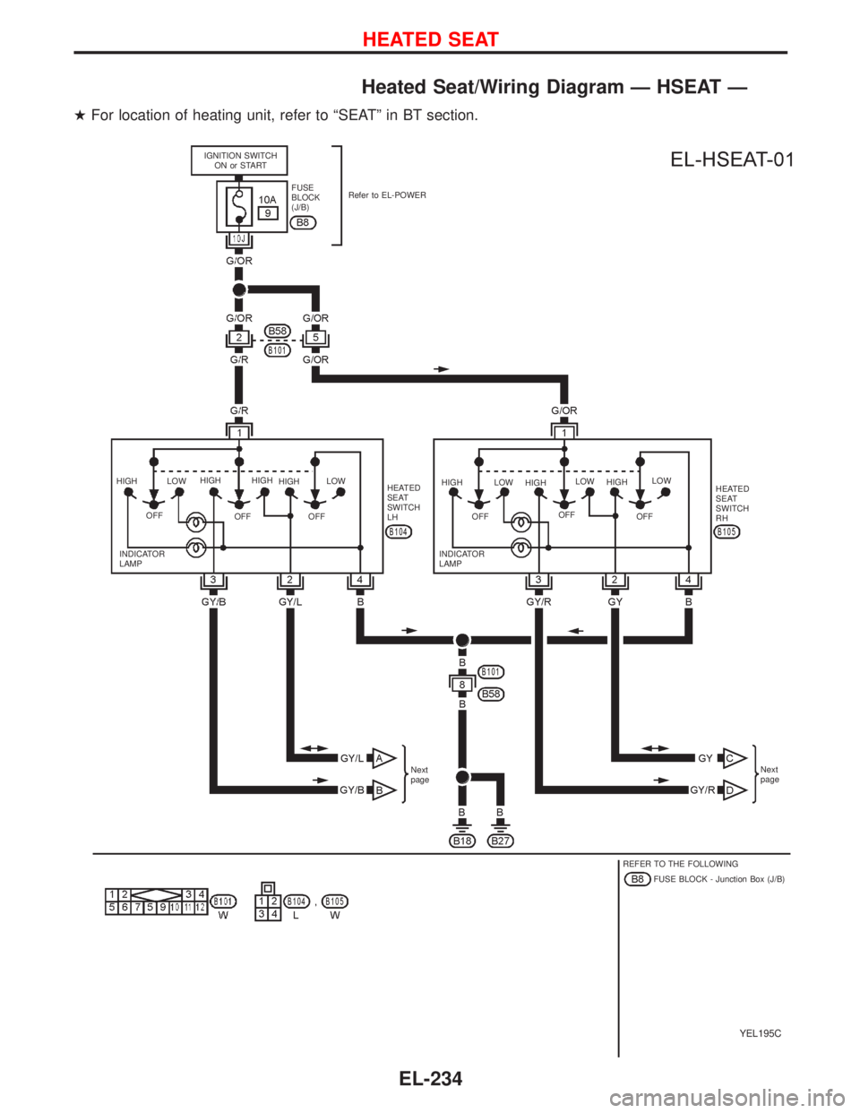
Heated Seat/Wiring Diagram—HSEAT—
�For location of heating unit, refer to“SEAT”in BT section.
YEL195C
IGNITION SWITCH
ON or START
FUSE
BLOCK
(J/B)Refer to EL-POWER
HIGH
OFFLOWHIGH
OFFHIGH
HIGH
OFFLOW
HEATED
SEAT
SWITCH
LHHIGH
OFFLOW
HIGH
OFFLOW
HIGH
OFFLOW
HEATED
SEAT
SWITCH
RH
INDICATOR
LAMPINDICATOR
LAMP
Next
pageNext
page
REFER TO THE FOLLOWING
FUSE BLOCK - Junction Box (J/B)
HEATED SEAT
EL-234

DOOR MIRROR HEATER
(DRIVER’S SIDE)
TIME
CONTRO")

To EL-DEF-03 Refer to EL-POWER.
: With door mirror heater
: 4 door models and
5 door hatchback models
: Wagon models
OFFON")
: RHD models
: With steering wheel switch
: With daytime light system
: Without daytime light sys")

FUSE BLOCK
(J/B): LHD models
: RHD models
: With daytime light system
: Without daytime light system
DAYTIME
LIGHT CONTROL
UNIT
FRONT
SPE")

: LHD models
: RHD modelsRefer to
EL-POWER.
SUNROOF
SWITCH
OPENCLOSEOPEN
SUNROOF")