Page 1319 of 2267

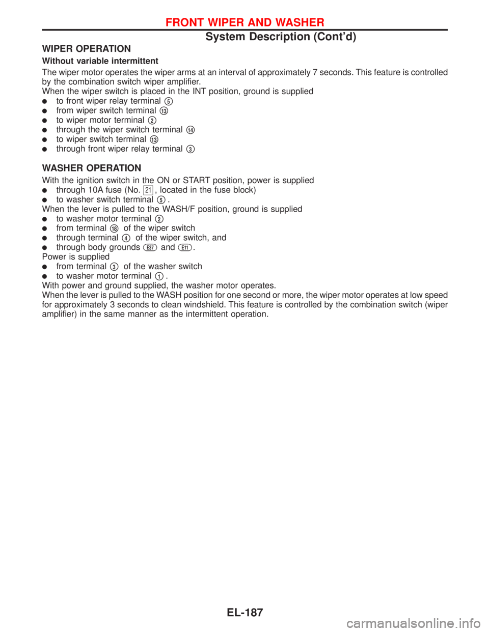
WIPER OPERATION
Without variable intermittent
The wiper motor operates the wiper arms at an interval of approximately 7 seconds. This feature is controlled
by the combination switch wiper amplifier.
When the wiper switch is placed in the INT position, ground is supplied
�to front wiper relay terminal�5
�from wiper switch terminal�13
�to wiper motor terminal�2
�through the wiper switch terminal�14
�to wiper switch terminal�13
�through front wiper relay terminal�3
WASHER OPERATION
With the ignition switch in the ON or START position, power is supplied
�through 10A fuse (No.21, located in the fuse block)
�to washer switch terminal�5.
When the lever is pulled to the WASH/F position, ground is supplied
�to washer motor terminal�2
�from terminal�18of the wiper switch
�through terminal�4of the wiper switch, and
�through body groundsE37andE11.
Power is supplied
�from terminal�3of the washer switch
�to washer motor terminal�1.
With power and ground supplied, the washer motor operates.
When the lever is pulled to the WASH position for one second or more, the wiper motor operates at low speed
for approximately 3 seconds to clean windshield. This feature is controlled by the combination switch (wiper
amplifier) in the same manner as the intermittent operation.
FRONT WIPER AND WASHER
System Description (Cont’d)
EL-187
Page 1320 of 2267
Wiring Diagram—WIPER—
YEL175C
IGNITION SWITCH
ON or START
FUSE BLOCK
(J/B)Refer to EL-POWER.
Next page
Next page
Next
pageCOMBINATION
SWITCH
(FRONT WIPER
SWITCH)
LOWHIGHFRONT WIPER
MOTOR
Next pageNext page: LHD models
: RHD models
REFER TO THE FOLLOWING
FUSE BLOCK - Junction Box (J/B) OFFMISTOFF
INT
LO HIOFF
INT
LOHI
FRONT WIPER AND WASHER
EL-188
Page 1325 of 2267

System Description
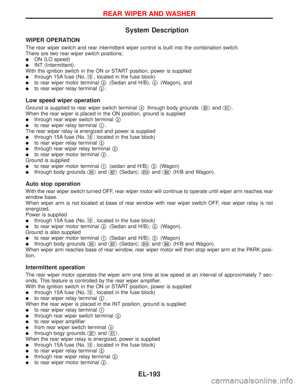
WIPER OPERATION
The rear wiper switch and rear intermittent wiper control is built into the combination switch.
There are two rear wiper switch positions:
�ON (LO speed)
�INT (Intermittent).
With the ignition switch in the ON or START position, power is supplied
�through 15A fuse (No.18, located in the fuse block)
�to rear wiper motor terminal�3(Sedan and H/B);�4(Wagon), and
�to rear wiper relay terminal�2.
Low speed wiper operation
Ground is supplied to rear wiper switch terminal�4through body groundsE37andE11.
When the rear wiper is placed in the ON position, ground is supplied
�through rear wiper switch terminal�2
�to rear wiper relay terminal�1.
The rear wiper relay is energized and power is supplied
�through 15A fuse (No.18, located in the fuse block)
�to rear wiper relay terminal�5
�through rear wiper relay terminal�3
�to rear wiper motor terminal�2.
Ground is supplied
�to rear wiper motor terminal�1(sedan and H/B);�3(Wagon)
�through body groundsB18andB27(Sedan);D110andB48(H/B and Wagon).
Auto stop operation
With the rear wiper switch turned OFF, rear wiper motor will continue to operate until wiper arm reaches rear
window base.
When wiper arm is not located at base of rear window with rear wiper switch OFF, rear wiper relay is not
energized.
Power is supplied
�through 15A fuse (No.18, located in the fuse block)
�to rear wiper motor terminal�3(Sedan and H/B);�4(Wagon).
Ground is also supplied
�to rear wiper motor terminal�1(Sedan and H/B);�3(Wagon)
�through body groundsB18andB27(Sedan);D110andB48(H/B and Wagon).
When wiper arm reaches base of rear window, rear wiper motor will then stop wiper arm at the PARK posi-
tion.
Intermittent operation
The rear wiper motor operates the wiper arm one time at low speed at an interval of approximately 7 sec-
onds. This feature is controlled by the rear wiper amplifier.
With the ignition switch in the ON or START position, power is supplied
�through 15A fuse (No.18, located in the fuse block)
�to rear wiper relay terminal�2.
When the rear wiper is placed in the INT position, ground is supplied
�to rear wiper relay terminal�1
�through rear wiper switch terminal�2
�to rear wiper amplifier
�from rear wiper switch terminal�4
�through bogy groundsE37andE11.
When the rear wiper relay is energized, power is supplied
�through 15A fuse (No.18, located in the fuse block)
�to rear wiper relay terminal�5
�through rear wiper relay terminal�3
�to rear wiper motor terminal�2.
REAR WIPER AND WASHER
EL-193
Page 1326 of 2267

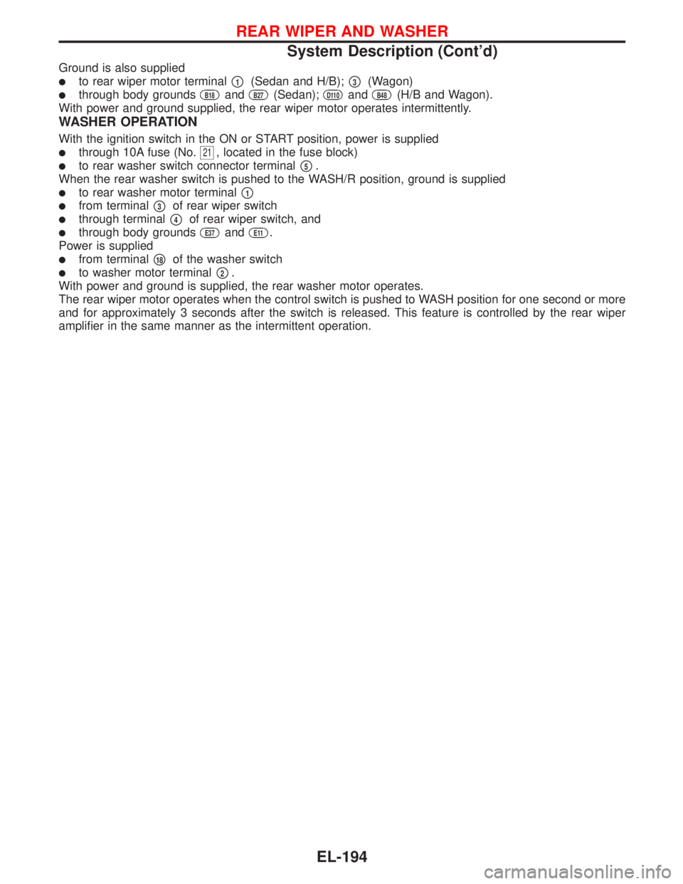
Ground is also supplied
�to rear wiper motor terminal�1(Sedan and H/B);�3(Wagon)
�through body groundsB18andB27(Sedan);D110andB48(H/B and Wagon).
With power and ground supplied, the rear wiper motor operates intermittently.
WASHER OPERATION
With the ignition switch in the ON or START position, power is supplied
�through 10A fuse (No.21, located in the fuse block)
�to rear washer switch connector terminal�5.
When the rear washer switch is pushed to the WASH/R position, ground is supplied
�to rear washer motor terminal�1
� �from terminal�3of rear wiper switch
�through terminal�4of rear wiper switch, and
�through body groundsE37andE11.
Power is supplied
�from terminal�18of the washer switch
�to washer motor terminal�2.
With power and ground is supplied, the rear washer motor operates.
The rear wiper motor operates when the control switch is pushed to WASH position for one second or more
and for approximately 3 seconds after the switch is released. This feature is controlled by the rear wiper
amplifier in the same manner as the intermittent operation.
REAR WIPER AND WASHER
System Description (Cont’d)
EL-194
Page 1332 of 2267
Wiring Diagram—HLC—
YEL319B
B
G
12
LG/Bd13GE104
2
E128
3
B R/B
B
A
5 LG/B4 G2 P/L
E126
P/L
P/L
3
OR/B1
R/B
E37E11
L
EL-HLC-01
E126
E104
E38
XH HD
HD 10A 30A
XH
HD
1 2 OR/B
BE38
M
B
B
12
E1281
36
24
5 3
241
5
BATTERYIGNITION SWITCH
ON or START
FUSE
BLOCK
(J/B)Refer to EL-POWER.: With XENON headlamp or day-
time light system
: Except
HEADLAMP
WASHER TIMERNext page
HEADLAMP
WASHER
MOTORHEADLAMP
WASHER
SWITCH
OFFON
REFER TO THE FOLLOWING
FUSE BLOCK - Junction Box (J/B)
HEADLAMP WASHER
EL-200
Page 1335 of 2267
Wiring Diagram—HORN—
Type-1
YEL180C
BATTERY
Refer to EL-POWER.: With gasoline engine
: With diesel engine
: With steering wheel switch
: Without steering wheel switch
HORN
RELAY
HORN
LOWHORN
HIGH
OFFON HORN
SWITCHHORN
SWITCH
REFER TO THE FOLLOWING
FUSE BLOCK - Junction Box (J/B)
FUSE BLOCK - Junction Box (J/B)
*: This connector is not shown in“HARNESS LAYOUT”of EL section.OFFONFUSE
BLOCK
(J/B)
SPIRAL
CABLE
HORN, CIGARETTE LIGHTER AND CLOCK
EL-203
Page 1336 of 2267
YEL181C
IGNITION SWITCH
ACC or ONBATTERYIGNITION SWITCH
ON or START
FUSE
BLOCK
(J/B)BATTERY
Refer to EL-POWER.
POWER
FUSE
15A: With gasoline engine
: With diesel engine
: With XENON headlamp,
gasoline engine
: Except
CLOCKCOMBINATION
METER
(CLOCK)
CIGARETTE
LIGHTER
SOCKET
POWER
SOCKET
REFER TO THE FOLLOWING
FUSE BLOCK - Junction Box (J/B) ACCESSORY
RELAY IGNITION
SWITCH OFF
ONST
ACC
ACC
HORN, CIGARETTE LIGHTER AND CLOCK
Wiring Diagram—HORN—(Cont’d)
EL-204
Page 1339 of 2267

System Description
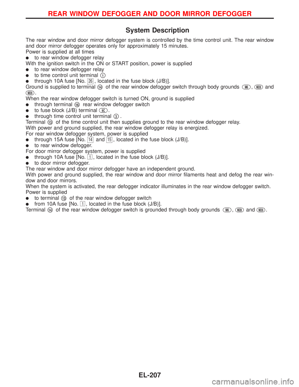
The rear window and door mirror defogger system is controlled by the time control unit. The rear window
and door mirror defogger operates only for approximately 15 minutes.
Power is supplied at all times
�to rear window defogger relay
With the ignition switch in the ON or START position, power is supplied
�to rear window defogger relay
�to time control unit terminal�1
�through 10A fuse [No.26, located in the fuse block (J/B)].
Ground is supplied to terminal
�14of the rear window defogger switch through body groundsM6,M28and
M26.
When the rear window defogger switch is turned ON, ground is supplied
�through terminal�16rear window defogger switch
�to fuse block (J/B) terminal9C.
�through time control unit terminal�3.
Terminal
�13of the time control unit then supplies ground to the rear window defogger relay.
With power and ground supplied, the rear window defogger relay is energized.
For rear window defogger system, power is supplied
�through 15A fuse [No.14and15, located in the fuse block (J/B)].
�to rear window defogger.
For door mirror defogger system, power is supplied
�through 10A fuse [No.1, located in the fuse block (J/B)].
�to door mirror defogger.
The rear window and door mirror defogger have an independent ground.
With power and ground supplied, the rear window and door mirror filaments heat and defog the rear win-
dow and door mirrors.
When the system is activated, the rear defogger indicator illuminates in the rear window defogger switch.
Power is supplied
�to terminal�13of the rear window defogger switch
�from 10A fuse [No.1, located in the fuse block (J/B)].
Terminal
�14of the rear window defogger switch is grounded through body groundsM6,M28andM26.
REAR WINDOW DEFOGGER AND DOOR MIRROR DEFOGGER
EL-207