Page 1368 of 2267

�through circuit breaker-1
�to power window relay.
With ignition switch in")
System Description
Power is supplied at all times
�from 40A fusible link (Lettere , located in the fusible link and fuse box)
�through circuit breaker-1
�to power window relay.
With ignition switch in ON or START position, power is supplied
�to power window relay.
Ground is supplied to power window relay
�through body groundsM6,M28andM26.
The power window relay is energized and power is supplied
�through power window relay.
�to power window main switch terminal�12,
�to passenger side power window sub-switch terminal�5,
�to rear power window sub-switch LH terminal�5,
�to rear power window sub-switch RH terminal�5.
MANUAL OPERATION
Driver’s door
Ground is supplied
�to front power window main switch terminals�2
�through body groundsB18andB27.
WINDOW UP
When a driver side switch in the power window main switch is pressed in the up position,
power is supplied
�to driver side power window regulator terminal�1
�through power window main switch terminal�3.
Ground is supplied
�to driver side power window regulator terminal�2
�through power window main switch terminal�4.
Then, the motor raises the window until the switch is released.
WINDOW DOWN
When a driver side switch in the power window main switch is pressed in the down position,
power is supplied
�to driver side power window regulator terminal�2
�through power window main switch terminal�4.
Ground is supplied
�to driver side power window regulator terminal�1
�through power window main switch terminal�3.
Then, the motor lowers the window until the switch is released.
Except driver’s door
Ground is supplied
�to power window main switch terminal�2
�through body groundsB18andB27.
POWER WINDOW
EL-236
Page 1375 of 2267

Trouble Diagnoses
Symptom Possible cause Repair order
None of the power windows can
be operated using any switch.1. 40A fusible link and circuit
breaker-1.
2. Grounds
B18andB27.
3. Power window relay.
4. Open/short in power window
main switch circuit.1. Check 40A fusible link (letter
e,located in fuse
and fusible link box) and circuit breaker-1. Turn
ignition switch to“ON”position and verify battery
positive voltage is present at terminal
�12of
power window main switch, and other switches as
follows.
2. Check grounds
B18andB27.
3. Check power window relay.
4. Check W/R wire between fuse block (J/B) and
power window main switch for open/short circuit.
Driver’s side power window can-
not be operated but other win-
dows can be operated.1. Driver’s side power window
regulator circuit.
2. Driver’s side power window
regulator.1. Check driver’s side power window regulator circuit
2. Check driver’s side power window regulator
One or more passenger power
windows cannot be operated.1. Power window switches (front
sub-switch, rear sub-switch
RH, rear sub-switch LH).
2. Power window regulators.
(Passenger side, rear LH,
rear LH.)
3. Power window main switch.
4. Power window circuit.1. Check power window switches (front sub-switch,
rear sub-switch RH, rear sub-switch LH)
2. Check power window regulators (front sub-switch,
rear sub-switch RH, rear sub-switch LH)
3. Check power window main switch
4-1. Check harnesses between power window main
switch and power window sub-switches for
open/short circuit.
4-2. Check harnesses between power window sub-
switches and power window regulators for open/
short circuit.
One or more passenger power
windows cannot be operated
using power window main switch
but can be operated by power
window sub-switches.1. Power window main switch. 1. Check power window main switch.
Driver’s side power window auto
function cannot be operated
using power window main switch.1. Power window main switch. 1. Check power window main switch.
Location of sub-switch Terminals
Passenger
�5
Rear RH�5
Rear LH�5
POWER WINDOW
EL-243
Page 1394 of 2267
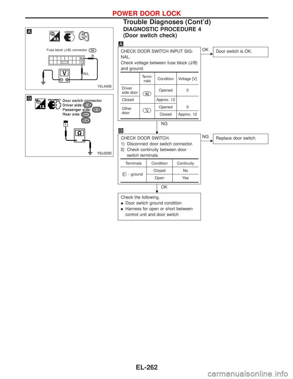
DIAGNOSTIC PROCEDURE 4
(Door switch check)
CHECK DOOR SWITCH INPUT SIG-
NAL.
Check voltage between fuse block (J/B)
and ground.
NG
�OK
Door switch is OK.
CHECK DOOR SWITCH.
1) Disconnect door switch connector.
2) Check continuity between door
switch terminals.
OK
�NG
Replace door switch.
Check the following.
�Door switch ground condition
�Harness for open or short between
control unit and door switch
Termi-
nalsCondition Voltage [V]
Driver
side door
16JOpened 0
Closed Approx. 12
Other
door
7JOpened 0
Closed Approx. 12
Terminals Condition Continuity
�1- groundClosed No
Open Yes
YEL450B
Fuse block (J/B) connector
YEL033D
�
�
POWER DOOR LOCK
Trouble Diagnoses (Cont’d)
EL-262
Page 1395 of 2267
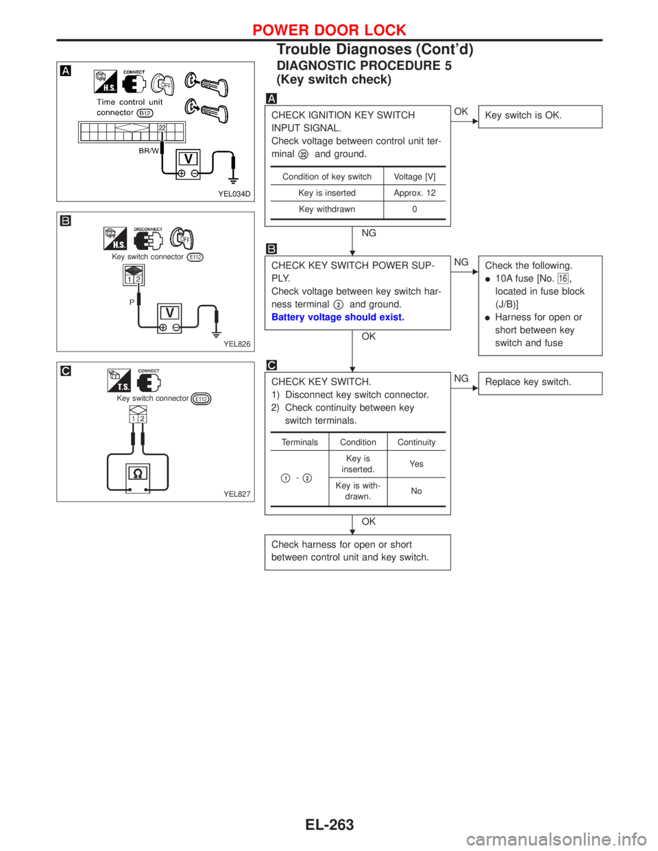
DIAGNOSTIC PROCEDURE 5
(Key switch check)
CHECK IGNITION KEY SWITCH
INPUT SIGNAL.
Check voltage between control unit ter-
minal
�22and ground.
NG
�OK
Key switch is OK.
CHECK KEY SWITCH POWER SUP-
PLY.
Check voltage between key switch har-
ness terminal
�2and ground.
Battery voltage should exist.
OK
�NG
Check the following.
�10A fuse [No.16,
located in fuse block
(J/B)]
�Harness for open or
short between key
switch and fuse
CHECK KEY SWITCH.
1) Disconnect key switch connector.
2) Check continuity between key
switch terminals.
OK
�NG
Replace key switch.
Check harness for open or short
between control unit and key switch.
Condition of key switch Voltage [V]
Key is inserted Approx. 12
Key withdrawn 0
Terminals Condition Continuity
�1-�2
Key is
inserted.Ye s
Key is with-
drawn.No
YEL034D
YEL826
Key switch connector
YEL827
Key switch connector
�
�
�
POWER DOOR LOCK
Trouble Diagnoses (Cont’d)
EL-263
Page 1397 of 2267
Component Parts Location
NEL562
Door key cylinder switch
Lock knob
Time control unit
Door lock actuator assembly
Door lock switch
Time control unitB11,B12,B96
Door key
cylinder switch
connector
D9,D17
Door lock actuator
assembly
D7,D16
Door switch
Fuse block (J/B)
POWER DOOR LOCK—Super Lock—
EL-265
Page 1424 of 2267

CHECK DOOR SWITCH INPUT SIG-
NAL.
Check voltage between fuse block (J/B)
and ground.
NG
�OK
Door switch is OK.
CHECK GRO")
DIAGNOSTIC PROCEDURE 5
—With driver door switch type-1—
(Door switch check)
CHECK DOOR SWITCH INPUT SIG-
NAL.
Check voltage between fuse block (J/B)
and ground.
NG
�OK
Door switch is OK.
CHECK GROUND CIRCUIT.
1) Disconnect driver side door switch
connector.
2) Check harness continuity between
terminal
�2and ground.
Continuity should exist.
OK
�NG
Repair harness or con-
nector.
CHECK DOOR SWITCH.
1) Disconnect door switch connector.
2) Check continuity between door
switch terminals.
OK
�NG
Replace door switch.
Check the following.
�Door switch ground condition (Except
driver side)
�Harness for open or short between
control unit and door switch
Termi-
nalsCondition Voltage [V]
Driver
side door
16JOpened 0
Closed Approx. 12
Other
door
7JOpened 0
Closed Approx. 12
Terminals ConditionContinu-
ity
Driver
side door
switch
�2-�3Closed No
Open Yes
Other
door
switches
�1-
groundClosed No
Open Yes
YEL450B
Fuse block (J/B) connector
YEL831
Door switch connector
Driver side:
YEL830
Door switch connector
Driver side:
Door switch connector
Passenger side:
Rear side:
�
�
�
POWER DOOR LOCK—Super Lock—
Trouble Diagnoses (Cont’d)
EL-292
Page 1425 of 2267
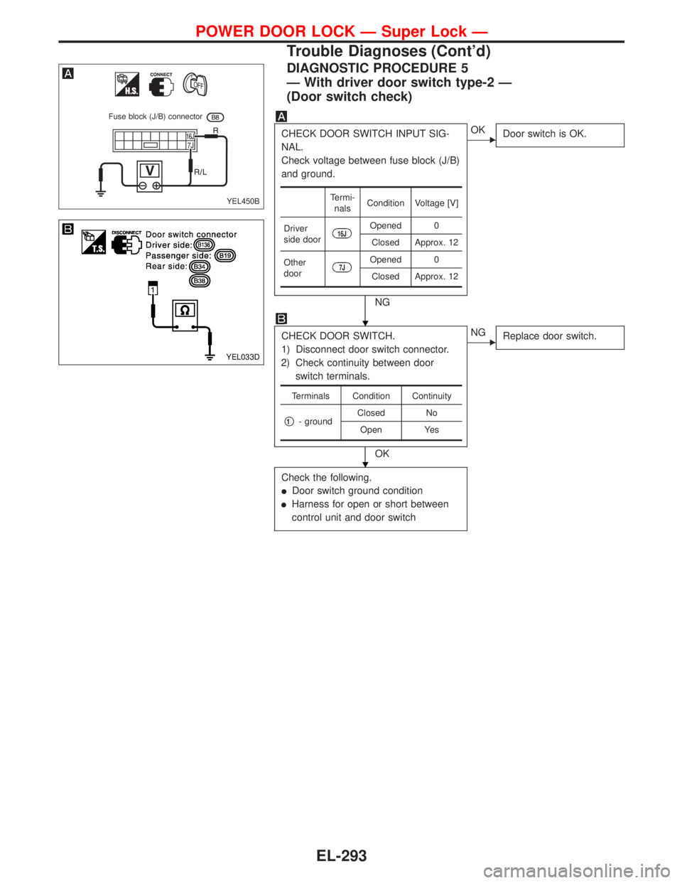
DIAGNOSTIC PROCEDURE 5
—With driver door switch type-2—
(Door switch check)
CHECK DOOR SWITCH INPUT SIG-
NAL.
Check voltage between fuse block (J/B)
and ground.
NG
�OK
Door switch is OK.
CHECK DOOR SWITCH.
1) Disconnect door switch connector.
2) Check continuity between door
switch terminals.
OK
�NG
Replace door switch.
Check the following.
�Door switch ground condition
�Harness for open or short between
control unit and door switch
Termi-
nalsCondition Voltage [V]
Driver
side door
16JOpened 0
Closed Approx. 12
Other
door
7JOpened 0
Closed Approx. 12
Terminals Condition Continuity
�1- groundClosed No
Open Yes
YEL450B
Fuse block (J/B) connector
YEL033D
�
�
POWER DOOR LOCK—Super Lock—
Trouble Diagnoses (Cont’d)
EL-293
Page 1427 of 2267

CHECK IGNITION KEY SWITCH
INPUT SIGNAL.
Check voltage between control unit ter-
minal
�22and ground.
NG
�OK
Key switch is OK.
CHECK KEY SWITCH POWER SUP-
PLY.")
DIAGNOSTIC PROCEDURE 7
(Key switch check)
CHECK IGNITION KEY SWITCH
INPUT SIGNAL.
Check voltage between control unit ter-
minal
�22and ground.
NG
�OK
Key switch is OK.
CHECK KEY SWITCH POWER SUP-
PLY.
Check voltage between key switch har-
ness terminal
�2and ground.
Battery voltage should exist.
OK
�NG
Check the following.
�10A fuse [No.16,
located in fuse block
(J/B)]
�Harness for open or
short between key
switch and fuse
CHECK KEY SWITCH.
1) Disconnect key switch connector.
2) Check continuity between key
switch terminals.
OK
�NG
Replace key switch.
Check harness for open or short
between control unit and key switch.
Condition of key switch Voltage [V]
Key is inserted Approx. 12
Key withdrawn 0
Terminals Condition Continuity
�1-�2
Key is
inserted.Ye s
Key is with-
drawn.No
DIAGNOSTIC PROCEDURE 8
(Ignition switch“ON”circuit check)
Terminals Ignition switch position
��OFF ACC ON
�1Ground 0V 0V Battery voltage
If NG, check the following.
�10A fuse [No.26, located in the fuse block (J/B)]
�Harness for open or short
YEL453B
Time control unit
connector
YEL826
Key switch connector
YEL827
Key switch connector
YEL454B Time control
unit connector
�
�
�
POWER DOOR LOCK—Super Lock—
Trouble Diagnoses (Cont’d)
EL-295