Page 1519 of 2267

YEL254C
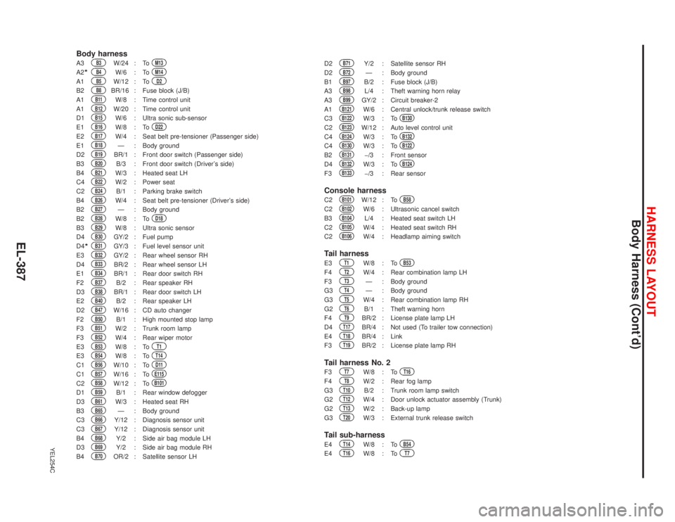
Body harnessA3
B3
W/24 : To
M13
A2�
B4
W/6 : To
M14
A1
B5
W/12 : To
D2
B2
B8
BR/16 : Fuse block (J/B)
A1
B11
W/8 : Time control unit
A1
B12
W/20 : Time control unit
D1
B15
W/6 : Ultra sonic sub-sensor
E1
B16
W/8 : To
D22
E2
B17
W/4 : Seat belt pre-tensioner (Passenger side)
E1
B18
—: Body ground
D2
B19
BR/1 : Front door switch (Passenger side)
B3
B20
B/3 : Front door switch (Driver’s side)
B4
B21
W/3 : Heated seat LH
C4
B22
W/2 : Power seat
C2
B24
B/1 : Parking brake switch
B4
B26
W/4 : Seat belt pre-tensioner (Driver’s side)
B2
B27
—: Body ground
B2
B28
W/8 : To
D18
B3
B29
W/8 : Ultra sonic sensor
D4
B30
GY/2 : Fuel pump
D4
�
B31
GY/3 : Fuel level sensor unit
E3
B32
GY/2 : Rear wheel sensor RH
D4
B33
BR/2 : Rear wheel sensor LH
E1
B34
BR/1 : Rear door switch RH
F2
B37
B/2 : Rear speaker RH
D3
B38
BR/1 : Rear door switch LH
E2
B40
B/2 : Rear speaker LH
D2
B47
W/16 : CD auto changer
F2
B50
B/1 : High mounted stop lamp
F3
B51
W/2 : Trunk room lamp
F3
B52
W/4 : Rear wiper motor
E3
B53
W/8 : To
T1
E3
B54
W/8 : To
T14
C1
B56
W/10 : To
D11
C1
B57
W/16 : To
E115
C2
B58
W/12 : To
B101
D1
B59
B/1 : Rear window defogger
D3
B61
W/3 : Heated seat RH
B3
B65
—: Body ground
C3
B66
Y/12 : Diagnosis sensor unit
C3
B67
Y/12 : Diagnosis sensor unit
B4
B68
Y/2 : Side air bag module LH
D3
B69
Y/2 : Side air bag module RH
B4
B70
OR/2 : Satellite sensor LHD2
B71
Y/2 : Satellite sensor RH
D2
B72
—: Body ground
B1
B97
B/2 : Fuse block (J/B)
A3
B98
L/4 : Theft warning horn relay
A3
B99
GY/2 : Circuit breaker-2
A1
B121
W/6 : Central unlock/trunk release switch
C3
B122
W/3 : To
B130
C2
B123
W/12 : Auto level control unit
C4
B124
W/3 : To
B132
C4
B130
W/3 : To
B122
B2
B131
�/3 : Front sensor
D4
B132
W/3 : To
B124
F3
B133
�/3 : Rear sensor
Console harnessC2
B101
W/12 : To
B58
C2
B102
W/6 : Ultrasonic cancel switch
B3
B104
L/4 : Heated seat switch LH
C2
B105
W/4 : Heated seat switch RH
C2
B106
W/4 : Headlamp aiming switch
Tail harnessE3
T1
W/8 : To
B53
F4
T2
W/4 : Rear combination lamp LH
F3
T3
—: Body ground
G3
T4
—: Body ground
G3
T5
W/4 : Rear combination lamp RH
G2
T6
B/1 : Theft warning horn
F4
T9
BR/2 : License plate lamp LH
D4
T17
BR/4 : Not used (To trailer tow connection)
E4
T18
BR/4 : Link
F3
T19
BR/2 : License plate lamp RH
Tail harness No. 2F3
T7
W/8 : To
T16
F4
T8
W/2 : Rear fog lamp
G3
T10
B/2 : Trunk room lamp switch
G2
T12
W/4 : Door unlock actuator assembly (Trunk)
G2
T13
W/2 : Back-up lamp
G3
T20
W/3 : External trunk release switch
Tail sub-harnessE4
T14
W/8 : To
B54
E4
T16
W/8 : To
T7
HARNESS LAYOUT
Body Harness (Cont’d)
EL-387
Page 1523 of 2267

YEL256C
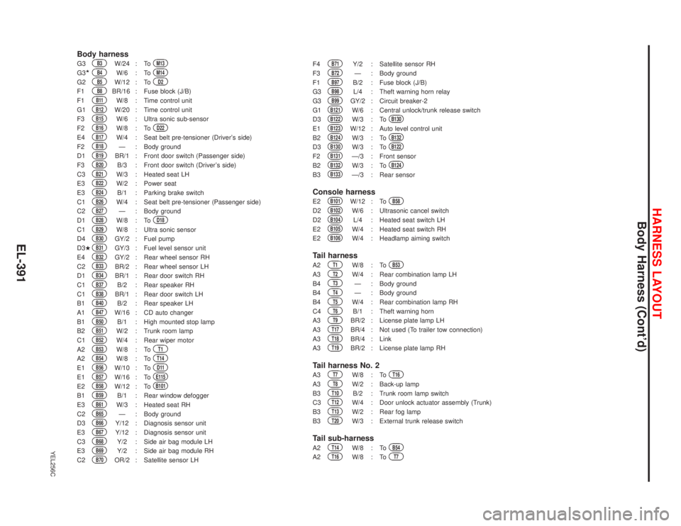
Body harnessG3
B3
W/24 : To
M13
G3�
B4
W/6 : To
M14
G2
B5
W/12 : To
D2
F1
B8
BR/16 : Fuse block (J/B)
F1
B11
W/8 : Time control unit
G1
B12
W/20 : Time control unit
F3
B15
W/6 : Ultra sonic sub-sensor
F2
B16
W/8 : To
D22
E4
B17
W/4 : Seat belt pre-tensioner (Driver’s side)
F2
B18
—: Body ground
D1
B19
BR/1 : Front door switch (Passenger side)
F3
B20
B/3 : Front door switch (Driver’s side)
C3
B21
W/3 : Heated seat LH
E3
B22
W/2 : Power seat
E3
B24
B/1 : Parking brake switch
C1
B26
W/4 : Seat belt pre-tensioner (Passenger side)
C2
B27
—: Body ground
D1
B28
W/8 : To
D18
C1
B29
W/8 : Ultra sonic sensor
D4
B30
GY/2 : Fuel pump
D3�
B31
GY/3 : Fuel level sensor unit
E4
B32
GY/2 : Rear wheel sensor RH
C2
B33
BR/2 : Rear wheel sensor LH
D1
B34
BR/1 : Rear door switch RH
C1
B37
B/2 : Rear speaker RH
C1
B38
BR/1 : Rear door switch LH
B1
B40
B/2 : Rear speaker LH
A1
B47
W/16 : CD auto changer
B1
B50
B/1 : High mounted stop lamp
B2
B51
W/2 : Trunk room lamp
C1
B52
W/4 : Rear wiper motor
A2
B53
W/8 : To
T1
A2
B54
W/8 : To
T14
E1
B56
W/10 : To
D11
E1
B57
W/16 : To
E115
E2
B58
W/12 : To
B101
B1
B59
B/1 : Rear window defogger
E3
B61
W/3 : Heated seat RH
C2
B65
—: Body ground
D3
B66
Y/12 : Diagnosis sensor unit
E3
B67
Y/12 : Diagnosis sensor unit
C3
B68
Y/2 : Side air bag module LH
E3
B69
Y/2 : Side air bag module RH
C2
B70
OR/2 : Satellite sensor LHF4
B71
Y/2 : Satellite sensor RH
F3
B72
—: Body ground
F1
B97
B/2 : Fuse block (J/B)
G3
B98
L/4 : Theft warning horn relay
G3
B99
GY/2 : Circuit breaker-2
G1
B121
W/6 : Central unlock/trunk release switch
D3
B122
W/3 : To
B130
E1
B123
W/12 : Auto level control unit
B2
B124
W/3 : To
B132
D3
B130
W/3 : To
B122
F2
B131
—/3 : Front sensor
B2
B132
W/3 : To
B124
B3
B133
—/3 : Rear sensor
Console harnessE2
B101
W/12 : To
B58
D2
B102
W/6 : Ultrasonic cancel switch
D2
B104
L/4 : Heated seat switch LH
E2
B105
W/4 : Heated seat switch RH
E2
B106
W/4 : Headlamp aiming switch
Tail harnessA2
T1
W/8 : To
B53
A3
T2
W/4 : Rear combination lamp LH
B4
T3
—: Body ground
B4
T4
—: Body ground
B4
T5
W/4 : Rear combination lamp RH
C4
T6
B/1 : Theft warning horn
A3
T9
BR/2 : License plate lamp LH
A3
T17
BR/4 : Not used (To trailer tow connection)
A3
T18
BR/4 : Link
A3
T19
BR/2 : License plate lamp RH
Tail harness No. 2A3
T7
W/8 : To
T16
A3
T8
W/2 : Back-up lamp
B3
T10
B/2 : Trunk room lamp switch
C3
T12
W/4 : Door unlock actuator assembly (Trunk)
B3
T13
W/2 : Rear fog lamp
B3
T20
W/3 : External trunk release switch
Tail sub-harnessA2
T14
W/8 : To
B54
A2
T16
W/8 : To
T7
HARNESS LAYOUT
Body Harness (Cont’d)
EL-391
Page 1535 of 2267
Room Lamp Harness
YEL267C
.R1
W/6 : To
M15
(RHD models)
R2
B/2 : Vanity mirror lamp (RHD models)
R3
W/2 : Sunroof motor
R4
W/8 : Sunroof switch
R5
W/2 : Spot lamp
R6
W/2 : Interior lamp (Without sunroof)
R8
W/2 : Interior lamp (With sunroof)
R9
B/2 : Vanity mirror lamp (LHD models)
R10
W/6 : Fuse block (J/B) (LHD models)
HARNESS LAYOUT
EL-403
Page 1556 of 2267

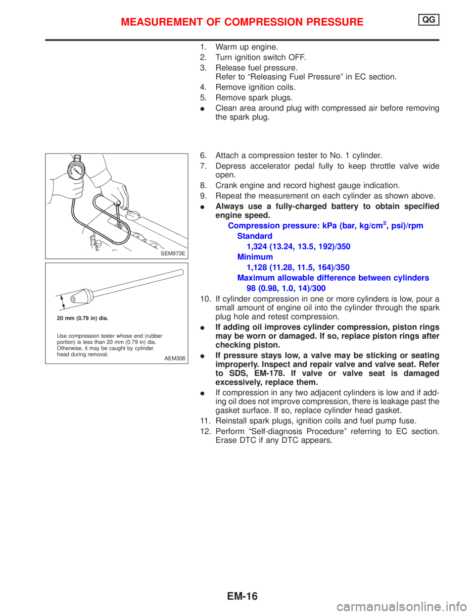
1. Warm up engine.
2. Turn ignition switch OFF.
3. Release fuel pressure.
Refer to ªReleasing Fuel Pressureº in EC section.
4. Remove ignition coils.
5. Remove spark plugs.
IClean area around plug with compressed air before removing
the spark plug.
6. Attach a compression tester to No. 1 cylinder.
7. Depress accelerator pedal fully to keep throttle valve wide
open.
8. Crank engine and record highest gauge indication.
9. Repeat the measurement on each cylinder as shown above.
IAlways use a fully-charged battery to obtain specified
engine speed.
Compression pressure: kPa (bar, kg/cm
2, psi)/rpm
Standard
1,324 (13.24, 13.5, 192)/350
Minimum
1,128 (11.28, 11.5, 164)/350
Maximum allowable difference between cylinders
98 (0.98, 1.0, 14)/300
10. If cylinder compression in one or more cylinders is low, pour a
small amount of engine oil into the cylinder through the spark
plug hole and retest compression.
IIf adding oil improves cylinder compression, piston rings
may be worn or damaged. If so, replace piston rings after
checking piston.
IIf pressure stays low, a valve may be sticking or seating
improperly. Inspect and repair valve and valve seat. Refer
to SDS, EM-178. If valve or valve seat is damaged
excessively, replace them.
IIf compression in any two adjacent cylinders is low and if add-
ing oil does not improve compression, there is leakage past the
gasket surface. If so, replace cylinder head gasket.
11. Reinstall spark plugs, ignition coils and fuel pump fuse.
12. Perform ªSelf-diagnosis Procedureº referring to EC section.
Erase DTC if any DTC appears.
SEM973E
AEM308 20 mm (0.79 in) dia.
Use compression tester whose end (rubber
portion) is less than 20 mm (0.79 in) dia.
Otherwise, it may be caught by cylinder
head during removal.
MEASUREMENT OF COMPRESSION PRESSUREQG
EM-16
Page 1792 of 2267
Terminal Arrangement
YEL232C To time control unit
UP
Spare fuse Fuel pump relay
Front fog lamp relay
Rear window defogger relay Power window relay
To air bag harness
To room lamp harness :
To main harness:
Ignition relay
Circuit breaker-1
Blower relayTo main harness
To engine
room harness
: LHD models
: RHD models
To body harness
FUSE BLOCK — Junction Box (J/B)
Page 1793 of 2267
Terminal Arrangement
YEL419B
With gasoline engine
With diesel engine
FUSE AND FUSIBLE LINK BOX
Page 1806 of 2267
Sample/Wiring Diagram Ð EXAMPL Ð
lFor Description, refer to GI-13.
YGI001
Refer to optional splice. BATTERY
Preceding
page
RELAY
MOTOR
MOTOR
CONTROL
MODULE
A/T models
M/T models
.REFER TO THE FOLLOWINGM1,E103FUSE BLOCK -
Junction Box (J/B)
M2FUSE BLOCK -
Junction Box (J/B)
E127FUSE BLOCK -
Junction Box (J/B) POWER JOINT
CONNECTOR-1
SWITCHTo EL-
EXAMPL
Next page
To GI-
EXAMPL-04
DIODE
POSITION
APOSITION
BSIGNAL
GND GNDUNIT
HOW TO READ WIRING DIAGRAMS
GI-11
Page 1808 of 2267

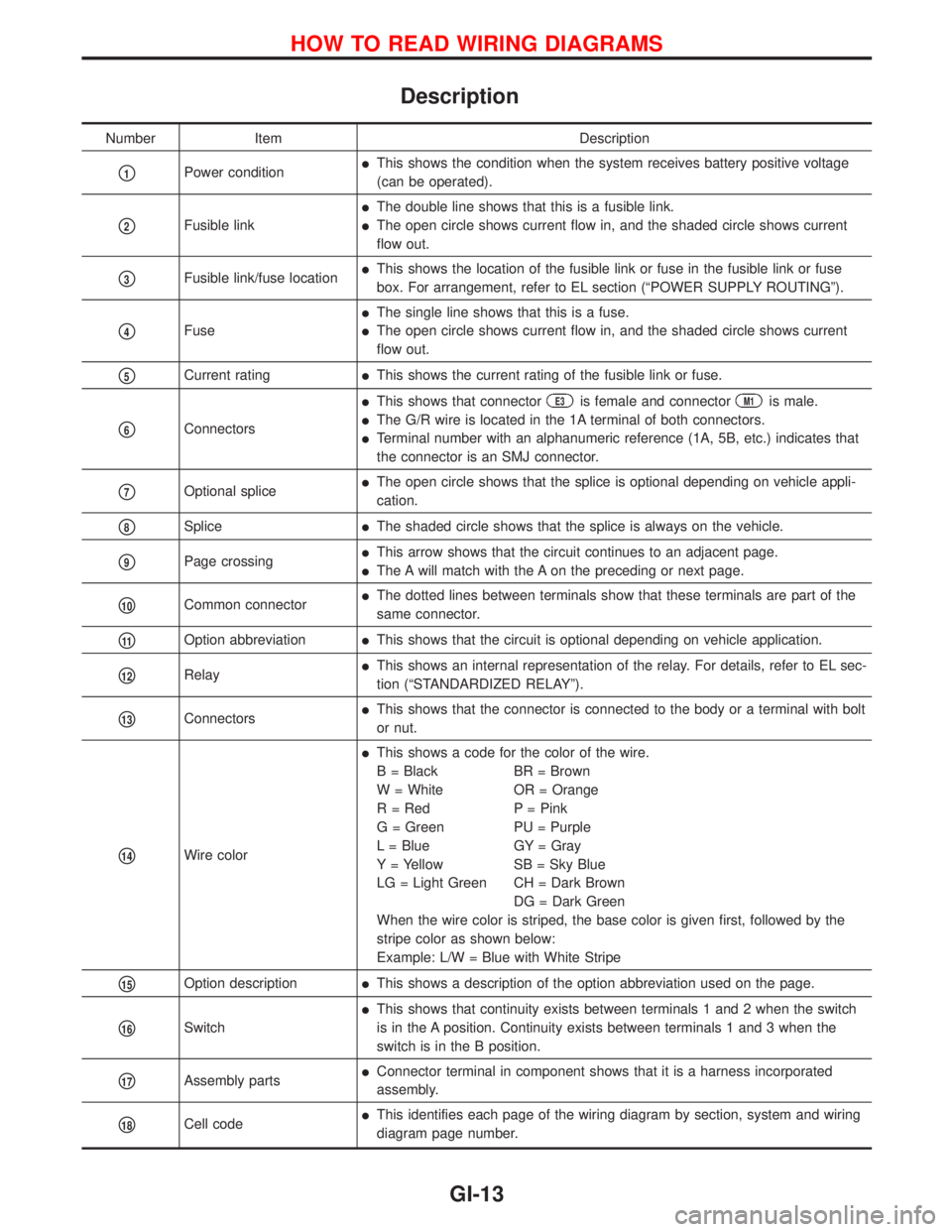
Description
Number Item Description
p1Power conditionlThis shows the condition when the system receives battery positive voltage
(can be operated).
p2Fusible link
lThe double line shows that this is a fusible link.
lThe open circle shows current flow in, and the shaded circle shows current
flow out.
p3Fusible link/fuse locationlThis shows the location of the fusible link or fuse in the fusible link or fuse
box. For arrangement, refer to EL section (ªPOWER SUPPLY ROUTINGº).
p4Fuse
lThe single line shows that this is a fuse.
lThe open circle shows current flow in, and the shaded circle shows current
flow out.
p5Current ratinglThis shows the current rating of the fusible link or fuse.
p6Connectors
lThis shows that connectorE3is female and connectorM1is male.
lThe G/R wire is located in the 1A terminal of both connectors.
lTerminal number with an alphanumeric reference (1A, 5B, etc.) indicates that
the connector is an SMJ connector.
p7Optional splicelThe open circle shows that the splice is optional depending on vehicle appli-
cation.
p8SplicelThe shaded circle shows that the splice is always on the vehicle.
p9Page crossinglThis arrow shows that the circuit continues to an adjacent page.
lThe A will match with the A on the preceding or next page.
p10Common connectorlThe dotted lines between terminals show that these terminals are part of the
same connector.
p11Option abbreviationlThis shows that the circuit is optional depending on vehicle application.
p12RelaylThis shows an internal representation of the relay. For details, refer to EL sec-
tion (ªSTANDARDIZED RELAYº).
p13ConnectorslThis shows that the connector is connected to the body or a terminal with bolt
or nut.
p14Wire color
lThis shows a code for the color of the wire.
B = Black BR = Brown
W = White OR = Orange
R = Red P = Pink
G = Green PU = Purple
L = Blue GY = Gray
Y = Yellow SB = Sky Blue
LG = Light Green CH = Dark Brown
DG = Dark Green
When the wire color is striped, the base color is given first, followed by the
stripe color as shown below:
Example: L/W = Blue with White Stripe
p15Option descriptionlThis shows a description of the option abbreviation used on the page.
p16Switch
lThis shows that continuity exists between terminals 1 and 2 when the switch
is in the A position. Continuity exists between terminals 1 and 3 when the
switch is in the B position.
p17Assembly partslConnector terminal in component shows that it is a harness incorporated
assembly.
p18Cell codelThis identifies each page of the wiring diagram by section, system and wiring
diagram page number.
HOW TO READ WIRING DIAGRAMS
GI-13