Page 1896 of 2267
WITH SR ENGINE or QG ENGINE
YHA342
Preceding
page
FUSE
BLOCK
(J/B)
AIR
CONDITIONER
RELAY
REFRIGERANT
PRESSURE
SENSOR
COMPRESSOR
ECM
REFER TO THE FOLLOWING
FUSE BLOCK - Junction Box (J/B)
FUSE BLOCK - Junction Box (J/B)
ELECTRICAL UNITS
CVT models
MT models
TROUBLE DIAGNOSESAUTO
Wiring Diagram Ð A/C Ð (Cont'd)
HA-47
Page 1898 of 2267
WITH GASOLINE ENGINE
YHA235
BR
17C
G
BR G
LG/R G/B23
15
G/B G/B
1*
LG/R
RFRL
ECM
2*
LG/R
LG/R
: 7
: 41
*
: E65
: E42
: F70
:F4:
:
BR12
BR
5H
,
2*: 13
: 9
GYGY
BRBB,GY,B
M1
HA-A/C-08
10A
11
21
E19
M
B
M140A
f
E45
21
M
BE28
B
E11B
E37 SQ
GA GA
SQ
F101
GA SQ
GA SQ
SQ
E94
GA M70
E125
SQ GA
GA
SQE127
SQ
GA
12
7 64
9 3
85 12
7 64
9 3
85
10F70 F43 2 14567
8
10911 12 13 14 15 16E125E45
2 1E19 E28 E94E127
F1013
12
5
IGNITION SWITCH
ON or START
FUSE BLOCK
(J/B)BATTERY
Refer to EL-POWER.
COOLING
FA N
RELAY-1
COOLING
FA N
MOTOR-2 COOLING
FA N
MOTOR-1
REFER TO THE FOLLOWING
FUSE BLOCK - Junction Box (J/B)
FUSE BLOCK - Junction Box (J/B)
ELECTRICAL UNITS : With GA engine
: With SR engine or QG engine
TROUBLE DIAGNOSESAUTO
Wiring Diagram Ð A/C Ð (Cont'd)
HA-49
Page 1899 of 2267
WITH DIESEL ENGINE
YHA344
IGNITION SWITCH
ON or START
FUSE
BLOCK (J/B)BATTERY
Refer to
EL-POWER
COOLING
FA N
MOTOR-1
COOLING
FA N
RELAY-2 COOLING
FA N
RELAY-1 COOLING
FA N
RELAY-3
To HA-A/C-07
TRIPLE-
PRESSURE
SWITCHCOOLING
FAN MOTOR-2
To HA-A/C-05
REFER TO THE FOLLOWING
FUSE BLOCK - Junction Box (J/B)
ELECTRICAL UNITS NORMAL
HIGH
LOWLOWHIGH
ECM
TROUBLE DIAGNOSESAUTO
Wiring Diagram Ð A/C Ð (Cont'd)
HA-50
Page 1901 of 2267

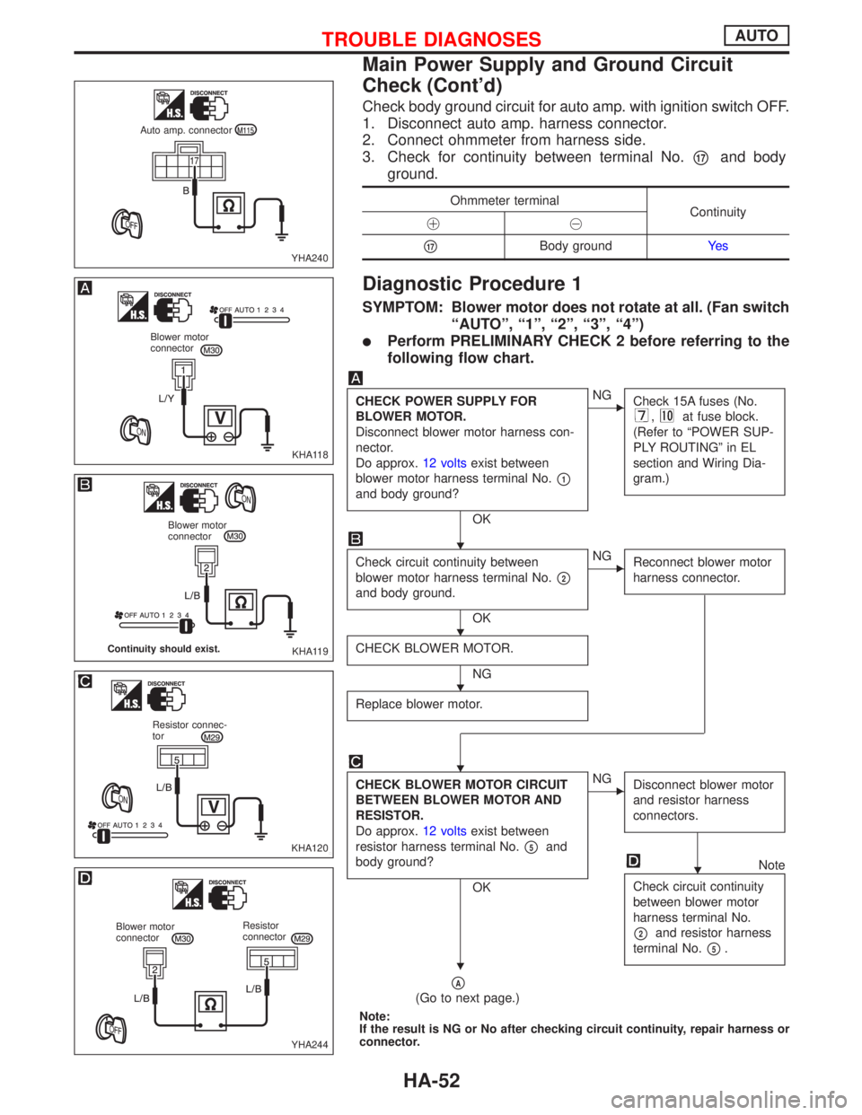
Check body ground circuit for auto amp. with ignition switch OFF.
1. Disconnect auto amp. harness connector.
2. Connect ohmmeter from harness side.
3. Check for continuity between terminal No.
p17and body
ground.
Ohmmeter terminal
Continuity
!@
p17Body groundYe s
Diagnostic Procedure 1
SYMPTOM: Blower motor does not rotate at all. (Fan switch
ªAUTOº, ª1º, ª2º, ª3º, ª4º)
lPerform PRELIMINARY CHECK 2 before referring to the
following flow chart.
CHECK POWER SUPPLY FOR
BLOWER MOTOR.
Disconnect blower motor harness con-
nector.
Do approx.12 voltsexist between
blower motor harness terminal No.
p1
and body ground?
OK
ENG
Check 15A fuses (No.
,at fuse block.
(Refer to ªPOWER SUP-
PLY ROUTINGº in EL
section and Wiring Dia-
gram.)
Check circuit continuity between
blower motor harness terminal No.
p2
and body ground.
OK
ENG
Reconnect blower motor
harness connector.
CHECK BLOWER MOTOR.
NG
Replace blower motor.
CHECK BLOWER MOTOR CIRCUIT
BETWEEN BLOWER MOTOR AND
RESISTOR.
Do approx.12 voltsexist between
resistor harness terminal No.
p5and
body ground?
OK
ENG
Disconnect blower motor
and resistor harness
connectors.
Note
Check circuit continuity
between blower motor
harness terminal No.
p2and resistor harness
terminal No.
p5.
pA
(Go to next page.)
Note:
If the result is NG or No after checking circuit continuity, repair harness or
connector.
YHA240 Auto amp. connector
KHA118
Blower motor
connector
KHA119
Blower motor
connector
Continuity should exist.
KHA120
Resistor connec-
tor
YHA244
Blower motor
connectorResistor
connector
H
H
H
H
H
H
TROUBLE DIAGNOSESAUTO
Main Power Supply and Ground Circuit
Check (Cont'd)
HA-52
Page 1903 of 2267

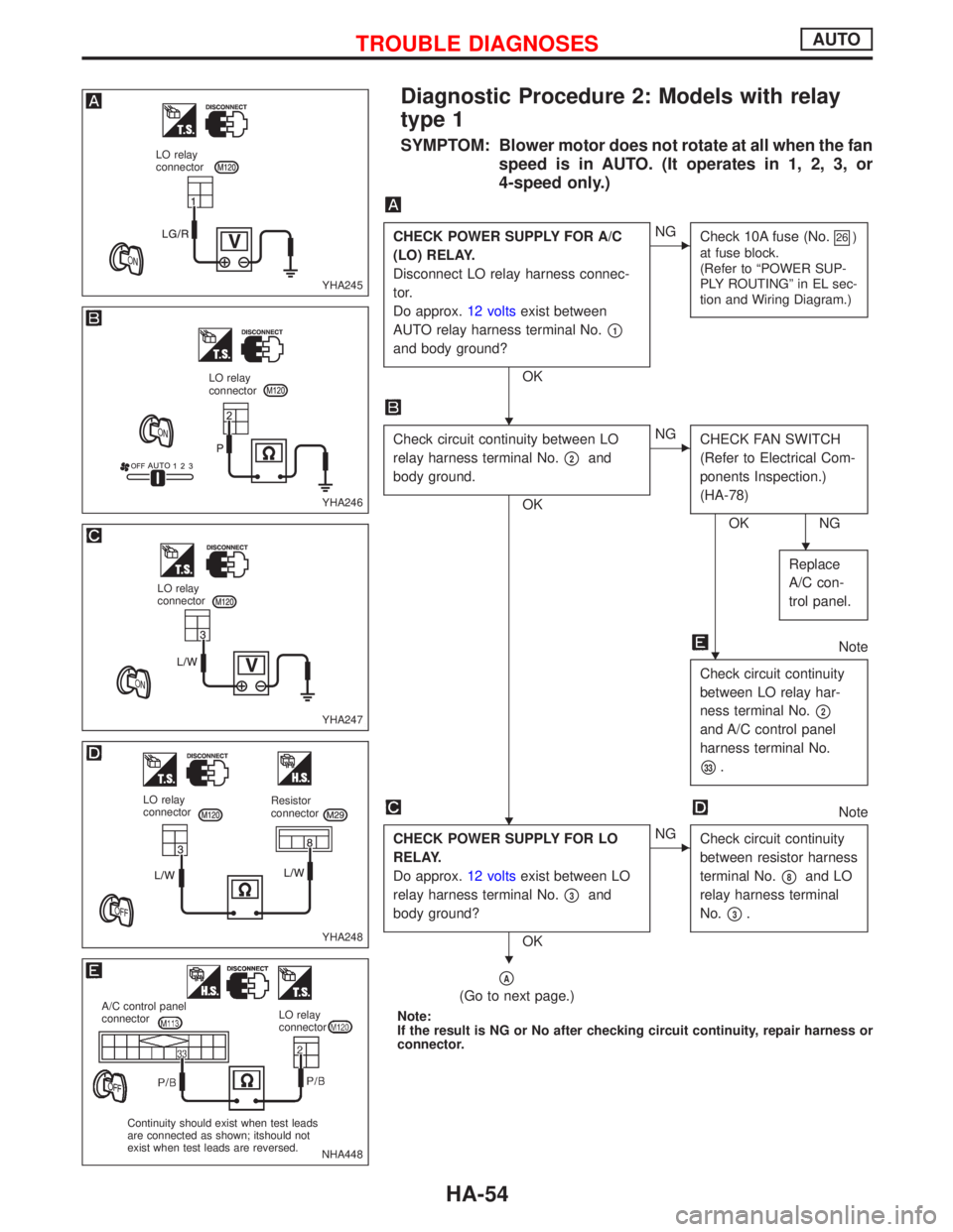
Diagnostic Procedure 2: Models with relay
type 1
SYMPTOM: Blower motor does not rotate at all when the fan
speed is in AUTO. (It operates in 1, 2, 3, or
4-speed only.)
CHECK POWER SUPPLY FOR A/C
(LO) RELAY.
Disconnect LO relay harness connec-
tor.
Do approx.12 voltsexist between
AUTO relay harness terminal No.
p1
and body ground?
OK
ENG
Check 10A fuse (No.26)
at fuse block.
(Refer to ªPOWER SUP-
PLY ROUTINGº in EL sec-
tion and Wiring Diagram.)
Check circuit continuity between LO
relay harness terminal No.
p2and
body ground.
OK
ENG
CHECK FAN SWITCH
(Refer to Electrical Com-
ponents Inspection.)
(HA-78)
OK NG
Replace
A/C con-
trol panel.
Note
Check circuit continuity
between LO relay har-
ness terminal No.
p2
and A/C control panel
harness terminal No.
p33.
Note
CHECK POWER SUPPLY FOR LO
RELAY.
Do approx.12 voltsexist between LO
relay harness terminal No.
p3and
body ground?
OK
ENG
Check circuit continuity
between resistor harness
terminal No.
p8and LO
relay harness terminal
No.
p3.
pA
(Go to next page.)
Note:
If the result is NG or No after checking circuit continuity, repair harness or
connector.
YHA245
LO relay
connector
YHA246
LO relay
connector
YHA247
LO relay
connector
YHA248
LO relay
connectorResistor
connector
NHA448
A/C control panel
connectorLO relay
connector
Continuity should exist when test leads
are connected as shown; itshould not
exist when test leads are reversed.
H
H
H
H
H
TROUBLE DIAGNOSESAUTO
HA-54
Page 1905 of 2267

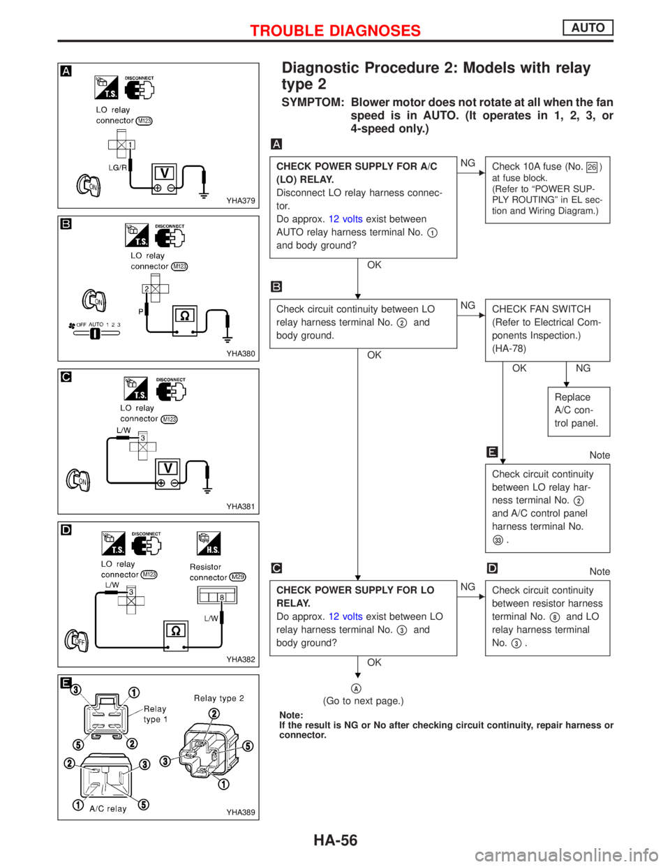
Diagnostic Procedure 2: Models with relay
type 2
SYMPTOM: Blower motor does not rotate at all when the fan
speed is in AUTO. (It operates in 1, 2, 3, or
4-speed only.)
CHECK POWER SUPPLY FOR A/C
(LO) RELAY.
Disconnect LO relay harness connec-
tor.
Do approx.12 voltsexist between
AUTO relay harness terminal No.
p1
and body ground?
OK
ENG
Check 10A fuse (No.26)
at fuse block.
(Refer to ªPOWER SUP-
PLY ROUTINGº in EL sec-
tion and Wiring Diagram.)
Check circuit continuity between LO
relay harness terminal No.
p2and
body ground.
OK
ENG
CHECK FAN SWITCH
(Refer to Electrical Com-
ponents Inspection.)
(HA-78)
OK NG
Replace
A/C con-
trol panel.
Note
Check circuit continuity
between LO relay har-
ness terminal No.
p2
and A/C control panel
harness terminal No.
p33.
Note
CHECK POWER SUPPLY FOR LO
RELAY.
Do approx.12 voltsexist between LO
relay harness terminal No.
p3and
body ground?
OK
ENG
Check circuit continuity
between resistor harness
terminal No.
p8and LO
relay harness terminal
No.
p3.
pA
(Go to next page.)
Note:
If the result is NG or No after checking circuit continuity, repair harness or
connector.
YHA379
YHA380
YHA381
YHA382
YHA389
H
H
H
H
H
TROUBLE DIAGNOSESAUTO
HA-56
Page 1910 of 2267

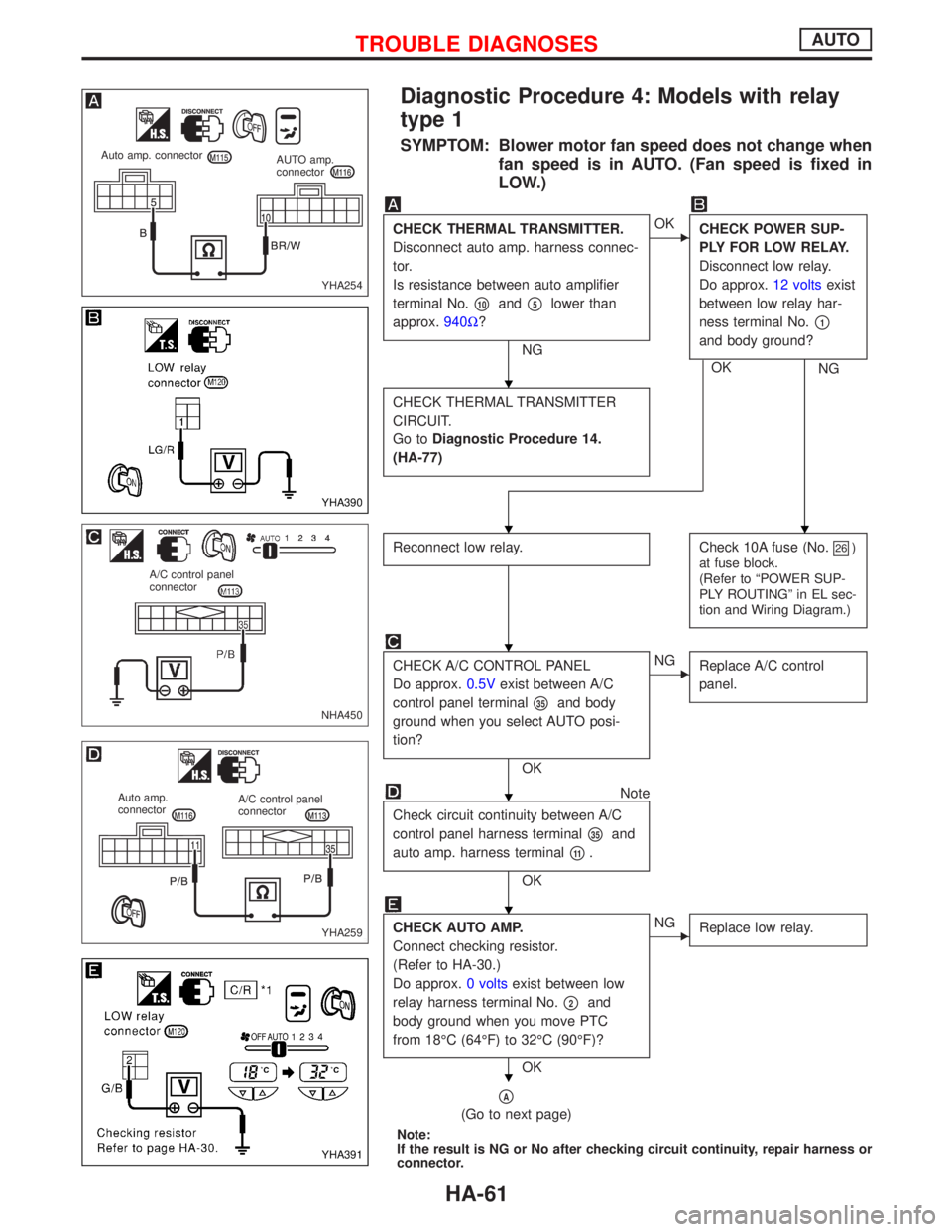
Diagnostic Procedure 4: Models with relay
type 1
SYMPTOM: Blower motor fan speed does not change when
fan speed is in AUTO. (Fan speed is fixed in
LOW.)
CHECK THERMAL TRANSMITTER.
Disconnect auto amp. harness connec-
tor.
Is resistance between auto amplifier
terminal No.
p10andp5lower than
approx.940W?
NG
EOK
CHECK POWER SUP-
PLY FOR LOW RELAY.
Disconnect low relay.
Do approx.12 voltsexist
between low relay har-
ness terminal No.
p1
and body ground?
OK
NG
CHECK THERMAL TRANSMITTER
CIRCUIT.
Go toDiagnostic Procedure 14.
(HA-77)
Reconnect low relay.Check 10A fuse (No.26)
at fuse block.
(Refer to ªPOWER SUP-
PLY ROUTINGº in EL sec-
tion and Wiring Diagram.)
CHECK A/C CONTROL PANEL
Do approx.0.5Vexist between A/C
control panel terminal
p35and body
ground when you select AUTO posi-
tion?
OK
ENG
Replace A/C control
panel.
Note
Check circuit continuity between A/C
control panel harness terminal
p35and
auto amp. harness terminal
p11.
OK
CHECK AUTO AMP.
Connect checking resistor.
(Refer to HA-30.)
Do approx.0 voltsexist between low
relay harness terminal No.
p2and
body ground when you move PTC
from 18ÉC (64ÉF) to 32ÉC (90ÉF)?
OK
ENG
Replace low relay.
pA
(Go to next page)
Note:
If the result is NG or No after checking circuit continuity, repair harness or
connector.
YHA254
Auto amp. connector
AUTO amp.
connector
YHA390
NHA450
A/C control panel
connector
YHA259
Auto amp.
connectorA/C control panel
connector
YHA391
H
HH
H
H
H
H
TROUBLE DIAGNOSESAUTO
HA-61
Page 1911 of 2267
pA
CHECK POWER SUPPLY FOR AUTO
AMP.
Disconnect auto amp. harness connec-
tor.
Do approx.12 voltsexist between auto
amp. harness terminal No.
p1and
body ground?
OK
ENG
Check 10A fuse (No.26)
at fuse block.
(Refer to ªPOWER SUP-
PLY ROUTINGº in EL sec-
tion and Wiring Diagram.)
Note
CHECK BODY GROUND CIRCUIT
FOR AUTO AMP.
Does continuity exist between auto
amp. harness terminal No.
p17and
body ground?
OK
Replace auto amp.
Note:
If the result is NG or No after checking circuit continuity, repair harness or
connector.
YHA257
Auto amp. connector
YHA258
Auto amp. connector
H
H
H
TROUBLE DIAGNOSESAUTO
Diagnostic Procedure 4: Models with relay
type 1 (Cont'd)
HA-62