Page 1877 of 2267

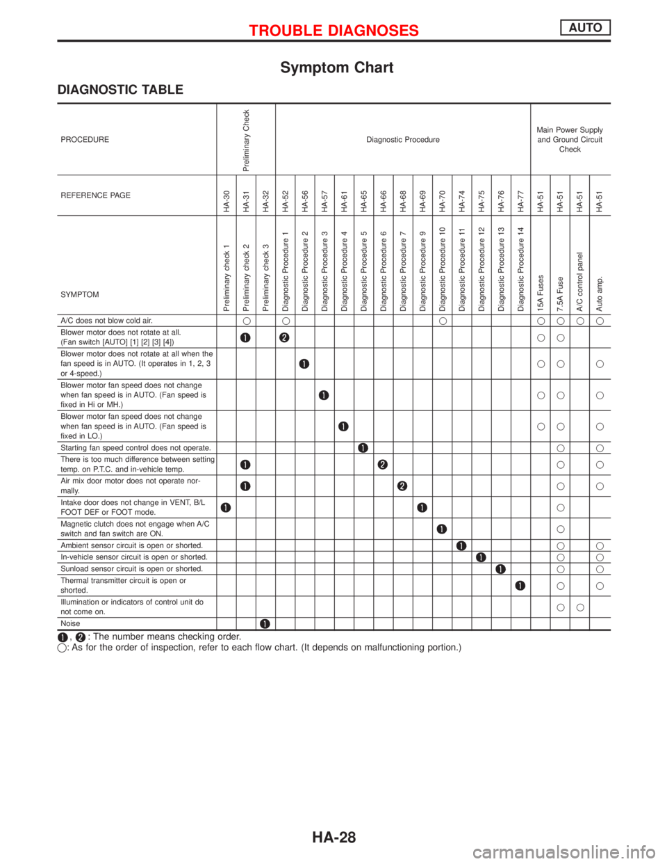
Symptom Chart
DIAGNOSTIC TABLE
PROCEDURE
Preliminary Check
Diagnostic ProcedureMain Power Supply
and Ground Circuit
Check
REFERENCE PAGE
HA-30
HA-31
HA-32
HA-52
HA-56
HA-57
HA-61
HA-65
HA-66
HA-68
HA-69
HA-70
HA-74
HA-75
HA-76
HA-77
HA-51
HA-51
HA-51
HA-51
SYMPTOM
Preliminary check 1
Preliminary check 2
Preliminary check 3
Diagnostic Procedure 1
Diagnostic Procedure 2
Diagnostic Procedure 3
Diagnostic Procedure 4
Diagnostic Procedure 5
Diagnostic Procedure 6
Diagnostic Procedure 7
Diagnostic Procedure 9
Diagnostic Procedure 10
Diagnostic Procedure 11
Diagnostic Procedure 12
Diagnostic Procedure 13
Diagnostic Procedure 14
15A Fuses
7.5A Fuse
A/C control panel
Auto amp.
A/C does not blow cold air.q q q qqqq
Blower motor does not rotate at all.
(Fan switch [AUTO] [1] [2] [3] [4])
qq
Blower motor does not rotate at all when the
fan speed is in AUTO. (It operates in 1, 2, 3
or 4-speed.)
qq q
Blower motor fan speed does not change
when fan speed is in AUTO. (Fan speed is
fixed in Hi or MH.)
qq q
Blower motor fan speed does not change
when fan speed is in AUTO. (Fan speed is
fixed in LO.)
qq q
Starting fan speed control does not operate.
qq
There is too much difference between setting
temp. on P.T.C. and in-vehicle temp.
qq
Air mix door motor does not operate nor-
mally.
qq
Intake door does not change in VENT, B/L
FOOT DEF or FOOT mode.
q
Magnetic clutch does not engage when A/C
switch and fan switch are ON.
q
Ambient sensor circuit is open or shorted.
qq
In-vehicle sensor circuit is open or shorted.
qq
Sunload sensor circuit is open or shorted.
qq
Thermal transmitter circuit is open or
shorted.
qq
Illumination or indicators of control unit do
not come on.qq
Noise
,: The number means checking order.
q: As for the order of inspection, refer to each flow chart. (It depends on malfunctioning portion.)
TROUBLE DIAGNOSESAUTO
HA-28
Page 1883 of 2267
pA
Malfunctioning blower motor fanMalfunctioning electrical circuitMalfunctioning blower motor inter-
nal circuit
Loose fan/Improper contact of fan
and case/Deformed fanDiscontinued wiring or component
circuits or poor connection/
Malfunctioning resistor, amplifier,
etc./ Burned out fuse or low bat-
tery voltage.
pB
Magnet clutch does not engage.Magnet clutch slippingBelt slipping
CHECK MAGNET CLUTCH
(coil circuit, disc-to-pulley clear-
ance).CHECK COMPRESSOR BELT
AND BELT TENSION.
CHECK ELECTRICAL CIRCUIT
(wiring, components circuit).EMalfunctioning internal parts of
clutch, compressor
CHECK ACTIVATION OF
SAFETY/PROTECTION DEVICES
(such as pressure switch, etc.).EForeign particles on clutch fric-
tional surface or excessive disc
clearance
EMalfunctioning electrical circuit
(poor connection, low battery
voltage, etc.)
HHH
HH
HHH
HH
H
H
TROUBLE DIAGNOSESAUTO
Performance Test Diagnoses (Cont'd)
HA-34
Page 1888 of 2267
Component Location
NHA290
In-vehicle sensorA/C control
panel
Sunload sensorA/C relay
.Triple-pressure switch
(With dieselengine)
Dual-pressure switch (With GA engine)
Pressure sensor (SRand QG engine)Ambient sensor
Compressor
Blower motor
fan resistor
.Auto amp.
HI.ML.LH.LO
relayBlower fan
motor relay
Compressor
.Ambient sensor
.
A/C relay
.Fuse block (J/B)
.Blower fan motor relaylBehind fuse block (J/B)
.
.Auto amp.
.MH relayLO relay
.ML relay.HI relay
Air mix door motor
Blower motor
Fan resistor.
Intake door motor
Sunload
sensor.
A/C control panel
.
.In-vehicle sensor
.Dual-pressure
switch/sensor
.Triple-pressure switch
Intake door
motor
Air mix
door motor
TROUBLE DIAGNOSESAUTO
HA-39
Page 1889 of 2267
Wiring Diagram Ð HEATER Ð
YHA336
IGNITION SWITCH
ONIGNITION SWITCH
ON or START
FUSE BLOCK
(J/B)Refer to EL-POWER.
INTAKE DOOR
MOTOR
BLOWER
MOTOR
FAN RESISTOR
RECFRERECFRERECIRCULATION
SWITCH
FA N
SWITCH
OFF
REFER TO THE FOLLOWING
FUSE BLOCK - Junction Box (J/B) FRE
REC
TROUBLE DIAGNOSESAUTO
HA-40
Page 1890 of 2267
Circuit Diagram Ð Air Conditioner
YHA337
IGNITION SWITCH
ON
FUSE
BLOWER
MOTORINTAKE
DOOR
MOTORTo illumination
systemCOMBINATION
METER
(WATER TEM-
PERATURE
GAUGE)IGNITION SWITCH
ON or START
FUSEFUSIBLE
LINKBATTERY
FUSIBLE
LINK
COOLING
FA N
MOTOR-1
THERMO
CONTROL
AMPLIFIERAIR CONDI-
TIONER
RELAYCOOLING
FA N
RELAY-1COOLING
FA N
RELAY-2COOLING
FA N
RELAY-3
TRIPLE-
PRESSURE
SWITCH
COOL-
ING FAN
RELAY-1
DUAL-
PRESSURE
SWITCH
COOLING
FA N
MOTOR-1COOLING
FA N
MOTOR-2COOLING
FA N
MOTOR-2
: With gasoline engine
: With diesel engine
: With GA engine
: With SR engine or
QG engine
: With GA engine or
diesel engine IACV-FIDC
SOLENOID
VA LV E THERMAL PRO-
TECTOR
COMPRESSOR THERMAL
TRANSMITTER A/C AUTO AMPIN-
VEHICLE
SENSORA/C CON-
TROL
PANEL
REFRIGENT
PRESSURE
SENSOR AMBIENT
SENSOR SUN LOAD
SENSOR A/C HIGH
RELAY
A/C MH
RELAY
A/C ML
RELAY
A/C LOW
RELAY FA N
RESISTOR
AIR MIX
DOOR
MOTOR
TROUBLE DIAGNOSESAUTO
HA-41
Page 1891 of 2267
Wiring Diagram Ð A/C Ð
YHA338
IGNITION SWITCH
ON or START
FUSE
BLOCK
(J/B)Refer to EL-POWER
To EL-ILL
SIDE
LIGHTSIDE
LIGHTA/C
CONTROL
PANEL
To HA-A/C-03
A/C
AUTO
AMP
REFER TO THE FOLLOWING
FUSE BLOCK - Junction Box (J/B)
TROUBLE DIAGNOSESAUTO
HA-42
Page 1892 of 2267
YHA229
L/Y
WWBR
6B
L/W L/Y L/R
14
13
12L/Y L/W
L/R L/Y L/W
L/RL/W
L/Y
L/R
11 L/B L/B
M112M84L/B
M1
HA-A/C-02
15A
715A
10
M30M84
M29
2 1 21 L/Y
M30
M
5
M29
678
165 678L/B L/B
M1
14 13 12 11 15
C
D
E B
IGNITION SWITCH
ON
FUSE
BLOCK
(J/B)Refer to EL-POWER
BLOWER
MOTOR
Next page
FA N
RESISTOR
Next page
REFER TO THE FOLLOWING
FUSE BLOCK - Junction Box (J/B)
TROUBLE DIAGNOSESAUTO
Wiring Diagram Ð A/C Ð (Cont'd)
HA-43
Page 1895 of 2267
YHA341
IGNITION SWITCH
ON
FUSE
BLOCK (J/B)Refer to EL-POWER.
To HA-A/C-07
Next page
To HA-A/C-07
To HA-A/C-09
Next page
AIR MIX
DOOR
MOTOR
A/C AUTO
AMP.
REFER TO THE FOLLOWING
FUSE BLOCK - Junction Box (J/B)
FUSE BLOCK - Junction Box (J/B) : With diesel engine
: With GA engine
:With GA engine or diesel engine
: With SR engine or QG engineA/C CON-
TROL
PANEL Next page
To HA-A/C-07 INTAKE
DOOR
MOTORTHERMISTORTHERMO
CONTROL
AMPLIFER
TROUBLE DIAGNOSESAUTO
Wiring Diagram Ð A/C Ð (Cont'd)
HA-46