1999 NISSAN PRIMERA fuse
[x] Cancel search: fusePage 1809 of 2267
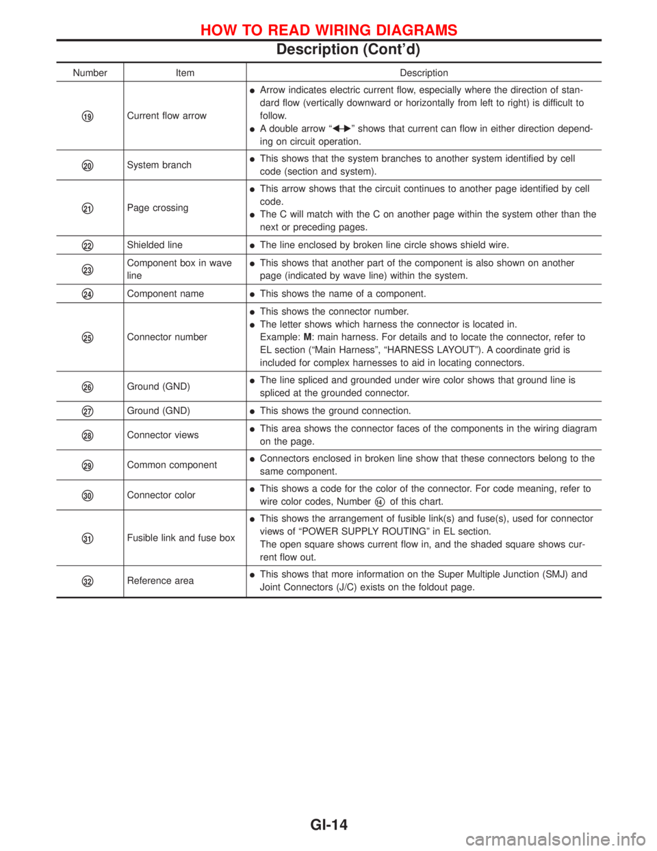
Number Item Description
p19Current flow arrow
lArrow indicates electric current flow, especially where the direction of stan-
dard flow (vertically downward or horizontally from left to right) is difficult to
follow.
lA double arrow ªFÐ
Eº shows that current can flow in either direction depend-
ing on circuit operation.
p20System branchlThis shows that the system branches to another system identified by cell
code (section and system).
p21Page crossing
lThis arrow shows that the circuit continues to another page identified by cell
code.
lThe C will match with the C on another page within the system other than the
next or preceding pages.
p22Shielded linelThe line enclosed by broken line circle shows shield wire.
p23Component box in wave
linelThis shows that another part of the component is also shown on another
page (indicated by wave line) within the system.
p24Component namelThis shows the name of a component.
p25Connector number
lThis shows the connector number.
lThe letter shows which harness the connector is located in.
Example:M: main harness. For details and to locate the connector, refer to
EL section (ªMain Harnessº, ªHARNESS LAYOUTº). A coordinate grid is
included for complex harnesses to aid in locating connectors.
p26Ground (GND)lThe line spliced and grounded under wire color shows that ground line is
spliced at the grounded connector.
p27Ground (GND)lThis shows the ground connection.
p28Connector viewslThis area shows the connector faces of the components in the wiring diagram
on the page.
p29Common componentlConnectors enclosed in broken line show that these connectors belong to the
same component.
p30Connector colorlThis shows a code for the color of the connector. For code meaning, refer to
wire color codes, Number
p14of this chart.
p31Fusible link and fuse box
lThis shows the arrangement of fusible link(s) and fuse(s), used for connector
views of ªPOWER SUPPLY ROUTINGº in EL section.
The open square shows current flow in, and the shaded square shows cur-
rent flow out.
p32Reference arealThis shows that more information on the Super Multiple Junction (SMJ) and
Joint Connectors (J/C) exists on the foldout page.
HOW TO READ WIRING DIAGRAMS
Description (Cont'd)
GI-14
Page 1824 of 2267
Circuit Inspection
INTRODUCTION
In general, testing electrical circuits is an easy task if it is approached in a logical and organized method.
Before beginning it is important to have all available information on the system to be tested. Also, get a
thorough understanding of system operation. Then you will be able to use the appropriate equipment and
follow the correct test procedure.
You may have to simulate vehicle vibrations while testing electrical components.Gently shakethe wiring
harness or electrical component to do this.
OPEN A circuit is open when there is no continuity through a section of the circuit.
SHORT There are two types of shorts.
lSHORT CIRCUITWhen a circuit contacts another circuit and causes the
normal resistance to change.
lSHORT TO GROUNDWhen a circuit contacts a ground source and grounds the
circuit.
TESTING FOR ªOPENSº IN THE CIRCUIT
Before you begin to diagnose and test the system, you should rough sketch a schematic of the system. This
will help you to logically walk through the diagnosis process. Drawing the sketch will also reinforce your
working knowledge of the system.
Continuity check method
The continuity check is used to find an open in the circuit. The Digital Multimeter (DMM) set on the resis-
tance function will indicate an open circuit as over limit (OL, no beep tone or no ohms symbol). Make sure
to always start with the DMM at the highest resistance level.
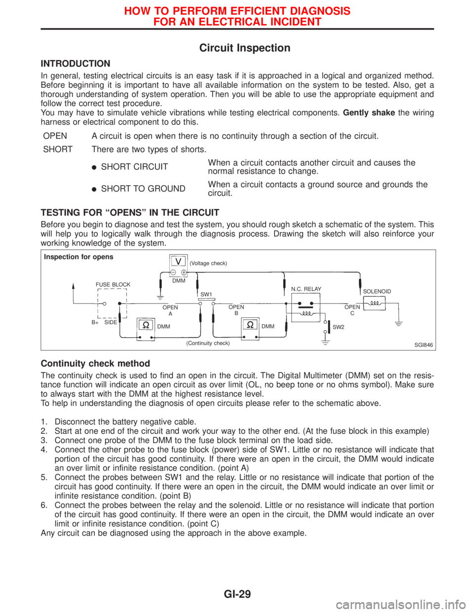
To help in understanding the diagnosis of open circuits please refer to the schematic above.
1. Disconnect the battery negative cable.
2. Start at one end of the circuit and work your way to the other end. (At the fuse block in this example)
3. Connect one probe of the DMM to the fuse block terminal on the load side.
4. Connect the other probe to the fuse block (power) side of SW1. Little or no resistance will indicate that
portion of the circuit has good continuity. If there were an open in the circuit, the DMM would indicate
an over limit or infinite resistance condition. (point A)
5. Connect the probes between SW1 and the relay. Little or no resistance will indicate that portion of the
circuit has good continuity. If there were an open in the circuit, the DMM would indicate an over limit or
infinite resistance condition. (point B)
6. Connect the probes between the relay and the solenoid. Little or no resistance will indicate that portion
of the circuit has good continuity. If there were an open in the circuit, the DMM would indicate an over
limit or infinite resistance condition. (point C)
Any circuit can be diagnosed using the approach in the above example.
SGI846
Inspection for opens
FUSE BLOCK
B+ SIDEDMM(Voltage check)
SW1N.C. RELAY
SOLENOID
OPEN
AOPEN
BOPEN
C
DMMDMM
SW2
(Continuity check)
HOW TO PERFORM EFFICIENT DIAGNOSIS
FOR AN ELECTRICAL INCIDENT
GI-29
Page 1825 of 2267
Voltage check method
To help in understanding the diagnosis of open circuits please refer to the previous schematic.
In any powered circuit, an open can be found by methodically checking the system for the presence of volt-
age. This is done by switching the DMM to the voltage function.
1. Connect one probe of the DMM to a known good ground.
2. Begin probing at one end of the circuit and work your way to the other end.
3. With SW1 open, probe at SW1 to check for voltage.
voltage; open is further down the circuit than SW1.
no voltage; open is between fuse block and SW1 (point A).
4. Close SW1 and probe at relay.
voltage; open is further down the circuit than the relay.
no voltage; open is between SW1 and relay (point B).
5. Close the relay and probe at the solenoid.
voltage; open is further down the circuit than the solenoid.
no voltage; open is between relay and solenoid (point C).
Any powered circuit can be diagnosed using the approach in the above example.
TESTING FOR ªSHORTSº IN THE CIRCUIT
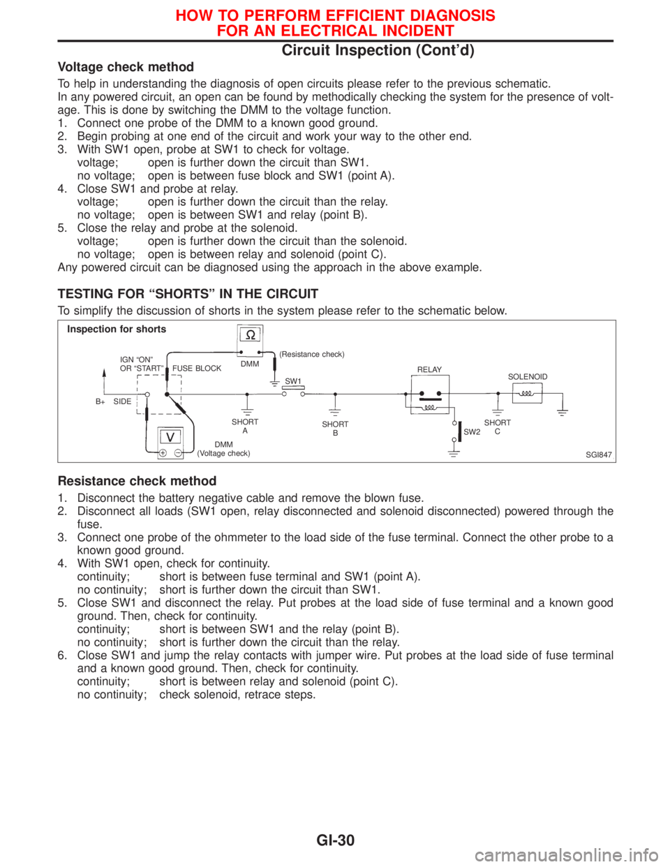
To simplify the discussion of shorts in the system please refer to the schematic below.
Resistance check method
1. Disconnect the battery negative cable and remove the blown fuse.
2. Disconnect all loads (SW1 open, relay disconnected and solenoid disconnected) powered through the
fuse.
3. Connect one probe of the ohmmeter to the load side of the fuse terminal. Connect the other probe to a
known good ground.
4. With SW1 open, check for continuity.
continuity; short is between fuse terminal and SW1 (point A).
no continuity; short is further down the circuit than SW1.
5. Close SW1 and disconnect the relay. Put probes at the load side of fuse terminal and a known good
ground. Then, check for continuity.
continuity; short is between SW1 and the relay (point B).
no continuity; short is further down the circuit than the relay.
6. Close SW1 and jump the relay contacts with jumper wire. Put probes at the load side of fuse terminal
and a known good ground. Then, check for continuity.
continuity; short is between relay and solenoid (point C).
no continuity; check solenoid, retrace steps.
SGI847
Inspection for shorts
IGN ªONº
OR ªSTARTº
B+ SIDEFUSE BLOCKDMM(Resistance check)
SW1RELAY
SOLENOID
SHORT
ASHORT
BSHORT
C
DMM
(Voltage check)SW2
HOW TO PERFORM EFFICIENT DIAGNOSIS
FOR AN ELECTRICAL INCIDENT
Circuit Inspection (Cont'd)
GI-30
Page 1826 of 2267
Voltage check method
1. Remove the blown fuse and disconnect all loads (i.e. SW1 open, relay disconnected and solenoid dis-
connected) powered through the fuse.
2. Turn the ignition key to the ON or START position. Verify battery voltage at the B
+side of the fuse ter-
minal (one lead on the B
+terminal side of the fuse block and one lead on a known good ground).
3. With SW1 open and the DMM leads across both fuse terminals, check for voltage.
voltage; short is between fuse block and SW1 (point A).
no voltage; short is further down the circuit than SW1.
4. With SW1 closed, relay and solenoid disconnected and the DMM leads across both fuse terminals, check
for voltage.
voltage; short is between SW1 and the relay (point B).
no voltage; short is further down the circuit than the relay.
5. With SW1 closed, relay contacts jumped with fused jumper wire check for voltage.
voltage; short is down the circuit of the relay or between the relay and the disconnected solenoid
(point C).
no voltage; retrace steps and check power to fuse block.
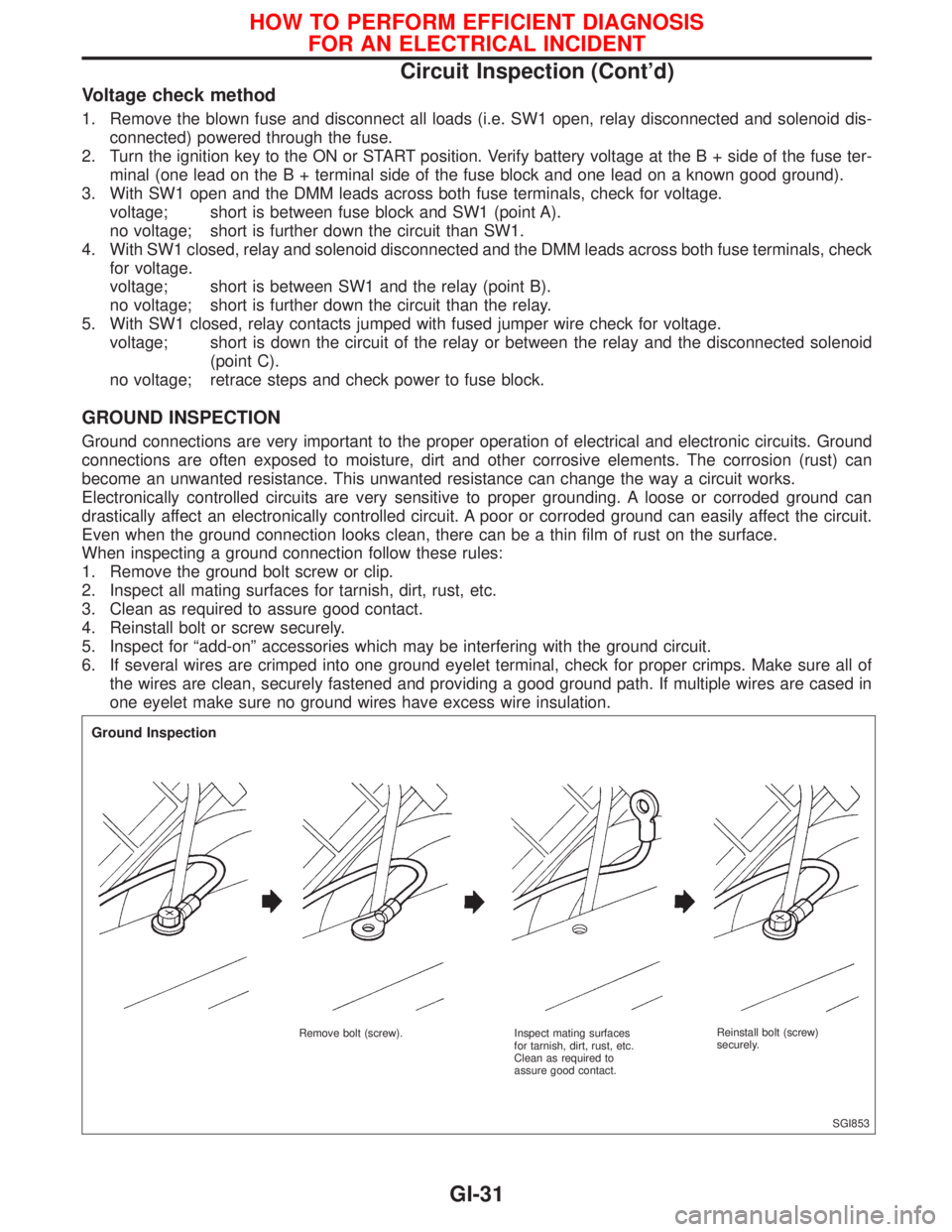
GROUND INSPECTION
Ground connections are very important to the proper operation of electrical and electronic circuits. Ground
connections are often exposed to moisture, dirt and other corrosive elements. The corrosion (rust) can
become an unwanted resistance. This unwanted resistance can change the way a circuit works.
Electronically controlled circuits are very sensitive to proper grounding. A loose or corroded ground can
drastically affect an electronically controlled circuit. A poor or corroded ground can easily affect the circuit.
Even when the ground connection looks clean, there can be a thin film of rust on the surface.
When inspecting a ground connection follow these rules:
1. Remove the ground bolt screw or clip.
2. Inspect all mating surfaces for tarnish, dirt, rust, etc.
3. Clean as required to assure good contact.
4. Reinstall bolt or screw securely.
5. Inspect for ªadd-onº accessories which may be interfering with the ground circuit.
6. If several wires are crimped into one ground eyelet terminal, check for proper crimps. Make sure all of
the wires are clean, securely fastened and providing a good ground path. If multiple wires are cased in
one eyelet make sure no ground wires have excess wire insulation.
SGI853
Ground Inspection
Remove bolt (screw). Inspect mating surfaces
for tarnish, dirt, rust, etc.
Clean as required to
assure good contact.Reinstall bolt (screw)
securely.
HOW TO PERFORM EFFICIENT DIAGNOSIS
FOR AN ELECTRICAL INCIDENT
Circuit Inspection (Cont'd)
GI-31
Page 1829 of 2267
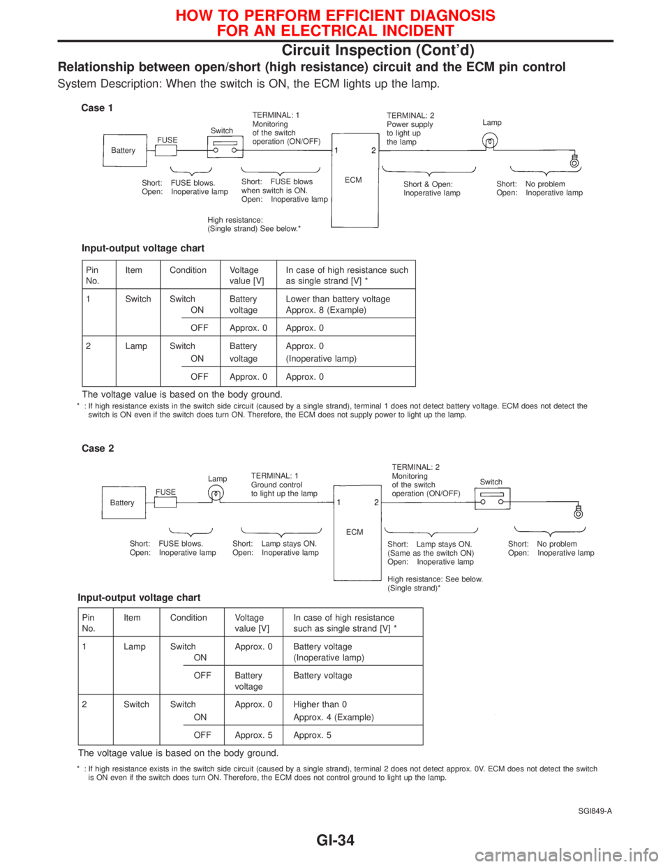
Relationship between open/short (high resistance) circuit and the ECM pin control
System Description: When the switch is ON, the ECM lights up the lamp.
SGI849-A
Case 1
BatteryFUSESwitchTERMINAL: 1
Monitoring
of the switch
operation (ON/OFF)TERMINAL: 2
Power supply
to light up
the lampLamp
Short: FUSE blows.
Open: Inoperative lampShort: FUSE blows
when switch is ON.
Open: Inoperative lamp
High resistance:
(Single strand) See below.*ECM
Short & Open:
Inoperative lampShort: No problem
Open: Inoperative lamp
Case 2
BatteryFUSELampTERMINAL: 1
Ground control
to light up the lampTERMINAL: 2
Monitoring
of the switch
operation (ON/OFF)Switch
Short: FUSE blows.
Open: Inoperative lampShort: Lamp stays ON.
Open: Inoperative lampShort: Lamp stays ON.
(Same as the switch ON)
Open: Inoperative lamp
High resistance: See below.
(Single strand)*Short: No problem
Open: Inoperative lamp ECM
Pin
No.Item Condition Voltage
value [V]In case of high resistance such
as single strand [V] *
1 Switch Switch Battery Lower than battery voltage
ON voltage Approx. 8 (Example)
OFF Approx. 0 Approx. 0
2 Lamp Switch Battery Approx. 0
ON voltage (Inoperative lamp)
OFF Approx. 0 Approx. 0
The voltage value is based on the body ground.
Input-output voltage chart
Pin
No.Item Condition Voltage
value [V]In case of high resistance
such as single strand [V] *
1 Lamp Switch Approx. 0 Battery voltage
ON (Inoperative lamp)
OFF Battery
voltageBattery voltage
2 Switch Switch Approx. 0 Higher than 0
ON Approx. 4 (Example)
OFF Approx. 5 Approx. 5
The voltage value is based on the body ground.
Input-output voltage chart
* : If high resistance exists in the switch side circuit (caused by a single strand), terminal 1 does not detect battery voltage. ECM does not detect the
switch is ON even if the switch does turn ON. Therefore, the ECM does not supply power to light up the lamp.
* : If high resistance exists in the switch side circuit (caused by a single strand), terminal 2 does not detect approx. 0V. ECM does not detect the switch
is ON even if the switch does turn ON. Therefore, the ECM does not control ground to light up the lamp.
HOW TO PERFORM EFFICIENT DIAGNOSIS
FOR AN ELECTRICAL INCIDENT
Circuit Inspection (Cont'd)
GI-34
Page 1832 of 2267
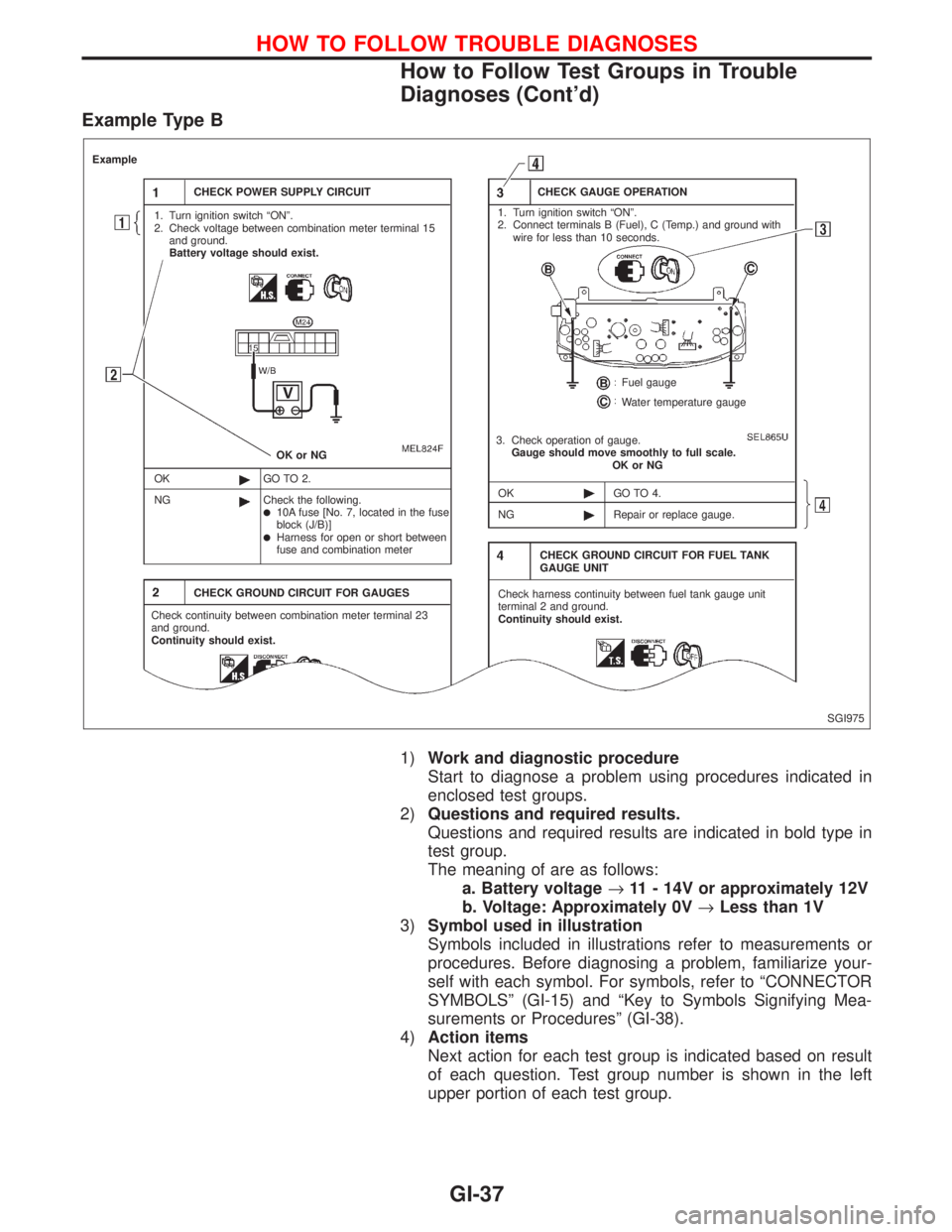
Example Type B
1)Work and diagnostic procedure
Start to diagnose a problem using procedures indicated in
enclosed test groups.
2)Questions and required results.
Questions and required results are indicated in bold type in
test group.
The meaning of are as follows:
a. Battery voltage®11 - 14V or approximately 12V
b. Voltage: Approximately 0V®Less than 1V
3)Symbol used in illustration
Symbols included in illustrations refer to measurements or
procedures. Before diagnosing a problem, familiarize your-
self with each symbol. For symbols, refer to ªCONNECTOR
SYMBOLSº (GI-15) and ªKey to Symbols Signifying Mea-
surements or Proceduresº (GI-38).
4)Action items
Next action for each test group is indicated based on result
of each question. Test group number is shown in the left
upper portion of each test group.
SGI975
Example
CHECK POWER SUPPLY CIRCUIT
1. Turn ignition switch ªONº.
2. Check voltage between combination meter terminal 15
and ground.
Battery voltage should exist.
OK or NG
OK
NGGO TO 2.
Check the following.
l10A fuse [No. 7, located in the fuse
block (J/B)]
lHarness for open or short between
fuse and combination meter
CHECK GROUND CIRCUIT FOR GAUGES
Check continuity between combination meter terminal 23
and ground.
Continuity should exist.CHECK GAUGE OPERATION
1. Turn ignition switch ªONº.
2. Connect terminals B (Fuel), C (Temp.) and ground with
wire for less than 10 seconds.
Fuel gauge
Water temperature gauge
3. Check operation of gauge.
Gauge should move smoothly to full scale.
OK or NG
OK
NGGO TO 4.
Repair or replace gauge.
CHECK GROUND CIRCUIT FOR FUEL TANK
GAUGE UNIT
Check harness continuity between fuel tank gauge unit
terminal 2 and ground.
Continuity should exist.
HOW TO FOLLOW TROUBLE DIAGNOSES
How to Follow Test Groups in Trouble
Diagnoses (Cont'd)
GI-37
Page 1833 of 2267
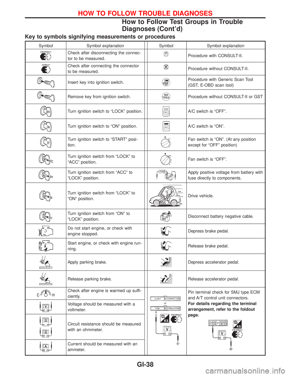
Key to symbols signifying measurements or procedures
Symbol Symbol explanation Symbol Symbol explanation
Check after disconnecting the connec-
tor to be measured.Procedure with CONSULT-II.
Check after connecting the connector
to be measured.Procedure without CONSULT-II.
Insert key into ignition switch.Procedure with Generic Scan Tool
(GST, E-OBD scan tool)
Remove key from ignition switch.Procedure without CONSULT-II or GST
Turn ignition switch to ªLOCKº position.A/C switch is ªOFFº.
Turn ignition switch to ªONº position.A/C switch is ªONº.
Turn ignition switch to ªSTARTº posi-
tion.Fan switch is ªONº. (At any position
except for ªOFFº position)
Turn ignition switch from ªLOCKº to
ªACCº position.Fan switch is ªOFFº.
Turn ignition switch from ªACCº to
ªLOCKº position.Apply positive voltage from battery with
fuse directly to components.
Turn ignition switch from ªLOCKº to
ªONº position.Drive vehicle.
Turn ignition switch from ªONº to
ªLOCKº position.Disconnect battery negative cable.
Do not start engine, or check with
engine stopped.Depress brake pedal.
Start engine, or check with engine run-
ning.Release brake pedal.
Apply parking brake.Depress accelerator pedal.
Release parking brake.Release accelerator pedal.
Check after engine is warmed up suffi-
ciently.Pin terminal check for SMJ type ECM
and A/T control unit connectors.
For details regarding the terminal
arrangement, refer to the foldout
page.
Voltage should be measured with a
voltmeter.
Circuit resistance should be measured
with an ohmmeter.
Current should be measured with an
ammeter.
HOW TO FOLLOW TROUBLE DIAGNOSES
How to Follow Test Groups in Trouble
Diagnoses (Cont'd)
GI-38
Page 1854 of 2267
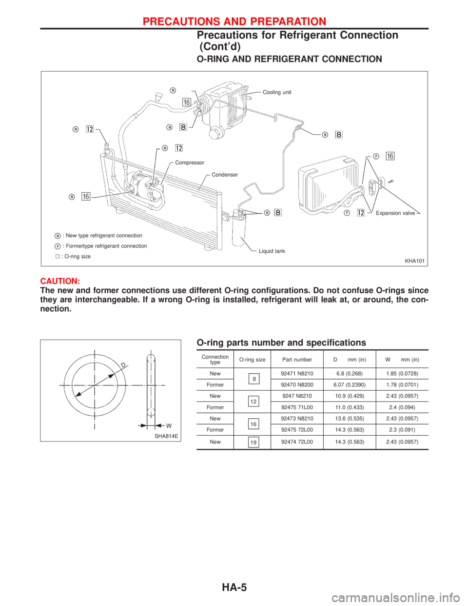
O-RING AND REFRIGERANT CONNECTION
CAUTION:
The new and former connections use different O-ring configurations. Do not confuse O-rings since
they are interchangeable. If a wrong O-ring is installed, refrigerant will leak at, or around, the con-
nection.
O-ring parts number and specifications
Connection
typeO-ring size Part number D mm (in) W mm (in)
New
892471 N8210 6.8 (0.268) 1.85 (0.0728)
Former 92470 N8200 6.07 (0.2390) 1.78 (0.0701)
New
129247 N8210 10.9 (0.429) 2.43 (0.0957)
Former 92475 71L00 11.0 (0.433) 2.4 (0.094)
New
1692473 N8210 13.6 (0.535) 2.43 (0.0957)
Former 92475 72L00 14.3 (0.563) 2.3 (0.091)
New
1992474 72L00 14.3 (0.563) 2.43 (0.0957)
KHA101
pN
pN
pN: New type refrigerant connection
pF: Formertype refrigerant connection
l: O-ring sizeLiquid tank
pNpFExpansion valve
pF
pN
Cooling unitpN
pN
pN
Compressor
Condenser
SHA814E
PRECAUTIONS AND PREPARATION
Precautions for Refrigerant Connection
(Cont'd)
HA-5