Page 550 of 2267
12 CHECK HARNESS CONTINUITY BETWEEN ECM RELAY AND ECM
1. Disconnect ECM harness connector.
2. Disconnect ECM relay.
SEF984W3. Check harness continuity between ECM terminals 110, 112 and relay terminal 5.
Refer to wiring diagram.
Continuity should exist.
4. Also check harness for short to ground and short to power.
OK or NG
OK©GO TO 14.
NG©GO TO 13.
13 DETECT MALFUNCTIONING PART
Check the following.
IHarness connectors E90, F73
IHarness for open or short between ECM relay and ECM
©Repair open circuit or short to ground or short to power in harness or connectors.
14 CHECK VOLTAGE BETWEEN ECM RELAY AND GROUND
Check voltage between relay terminals 1, 3 and ground with CONSULT-II or tester.
SEF985WVoltage: Battery voltage
OK or NG
OK©GO TO 16.
NG©GO TO 15.
15 DETECT MALFUNCTIONING PART
Check the harness for open or short between ECM relay and fuse.
©Repair harness or connectors.
TROUBLE DIAGNOSIS FOR POWER SUPPLYQG16I18DE
Main Power Supply and Ground Circuit (Cont'd)
EC-108
Page 611 of 2267

Diagnostic ProcedureNLEC0142
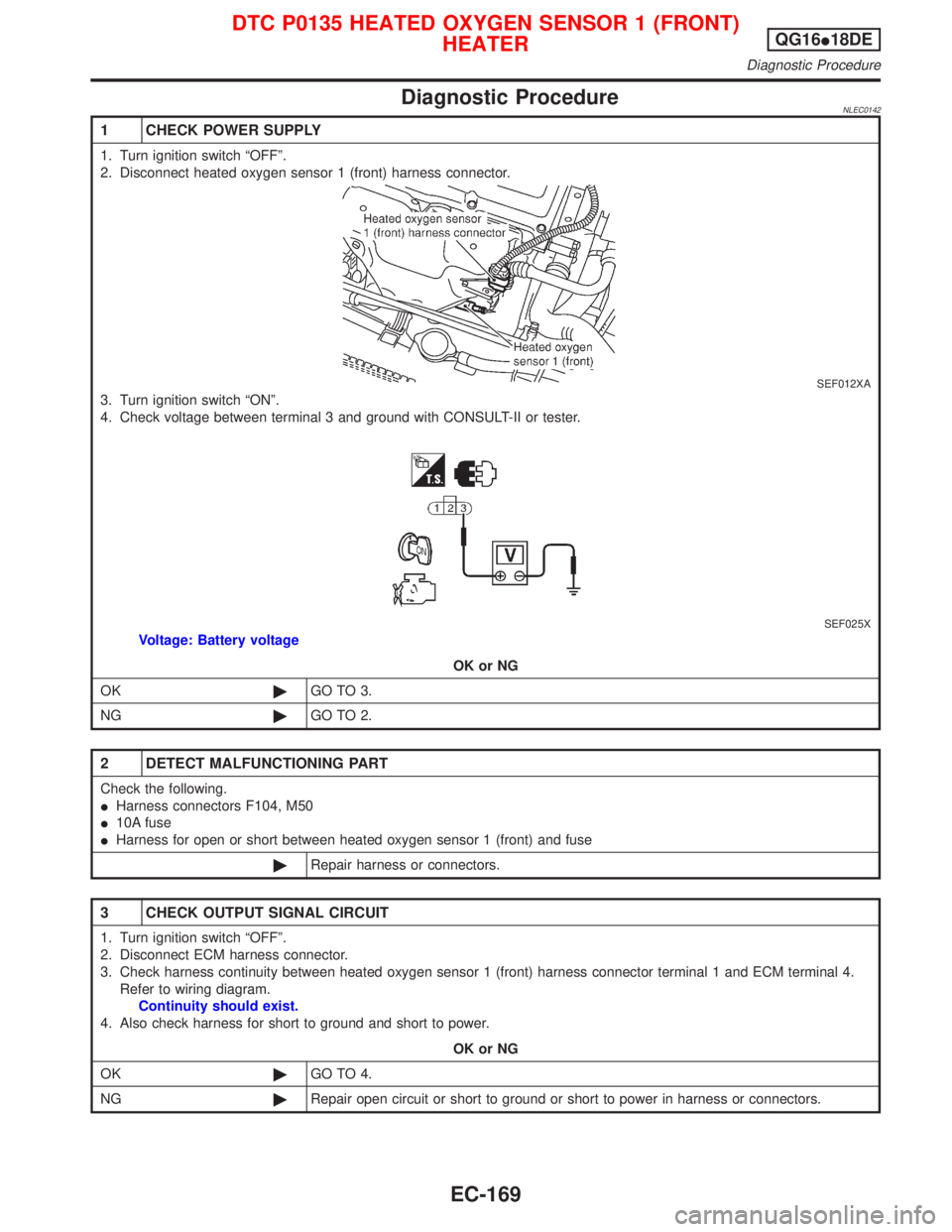
1 CHECK POWER SUPPLY
1. Turn ignition switch ªOFFº.
2. Disconnect heated oxygen sensor 1 (front) harness connector.
SEF012XA
3. Turn ignition switch ªONº.
4. Check voltage between terminal 3 and ground with CONSULT-II or tester.
SEF025X
Voltage: Battery voltage
OK or NG
OK©GO TO 3.
NG©GO TO 2.
2 DETECT MALFUNCTIONING PART
Check the following.
IHarness connectors F104, M50
I10A fuse
IHarness for open or short between heated oxygen sensor 1 (front) and fuse
©Repair harness or connectors.
3 CHECK OUTPUT SIGNAL CIRCUIT
1. Turn ignition switch ªOFFº.
2. Disconnect ECM harness connector.
3. Check harness continuity between heated oxygen sensor 1 (front) harness connector terminal 1 and ECM terminal 4.
Refer to wiring diagram.
Continuity should exist.
4. Also check harness for short to ground and short to power.
OK or NG
OK©GO TO 4.
NG©Repair open circuit or short to ground or short to power in harness or connectors.
DTC P0135 HEATED OXYGEN SENSOR 1 (FRONT)
HEATERQG16I18DE
Diagnostic Procedure
EC-169
Page 648 of 2267
Diagnostic ProcedureNCEC0186
1 CHECK POWER SUPPLY
1. Turn ignition switch ªOFFº.
2. Disconnect heated oxygen sensor 2 (rear) harness connector.
SEF033X3. Turn ignition switch ªONº.
4. Check voltage between terminal 4 and ground.
SEF047XVoltage: Battery voltage
OK or NG
OK©GO TO 3.
NG©GO TO 2.
2 DETECT MALFUNCTIONING PART
Check the following.
IHarness connectors F104, M50
IHarness for open or short between heated oxygen sensor 2 (rear) and fuse
I10A fuse
©Repair harness or connectors.
3 CHECK OUTPUT SIGNAL CIRCUIT
1. Turn ignition switch ªOFFº.
2. Disconnect ECM harness connector.
3. Check harness continuity between heated oxygen sensor 2 (rear) harness connector terminal 1 and ECM terminal 3.
Refer to wiring diagram.
Continuity should exist.
4. Also check harness for short to ground and short to power.
OK or NG
OK©GO TO 5.
NG©GO TO 4.
DTC P0141 HEATED OXYGEN SENSOR 2 HEATER
(REAR)QG16I18DE
Diagnostic Procedure
EC-206
Page 706 of 2267
Wiring DiagramNCEC0253
YEC783
: Detectable line for DTC
: Non-detectable line for DTC
ECM EVAP CANISTER
PURGE VOLUME
CONTROL SOLENOID
VA LV EFUSE
BLOCK
(J/B)Refer to EL-POWER. IGNITION SWITCH
ON or START
Refer to last page (Foldout page)
DTC P0443 EVAP CANISTER PURGE VOLUME CONTROL
SOLENOID VALVE (CIRCUIT)QG16I18DE
Wiring Diagram
EC-264
Page 707 of 2267

Diagnostic ProcedureNCEC0254
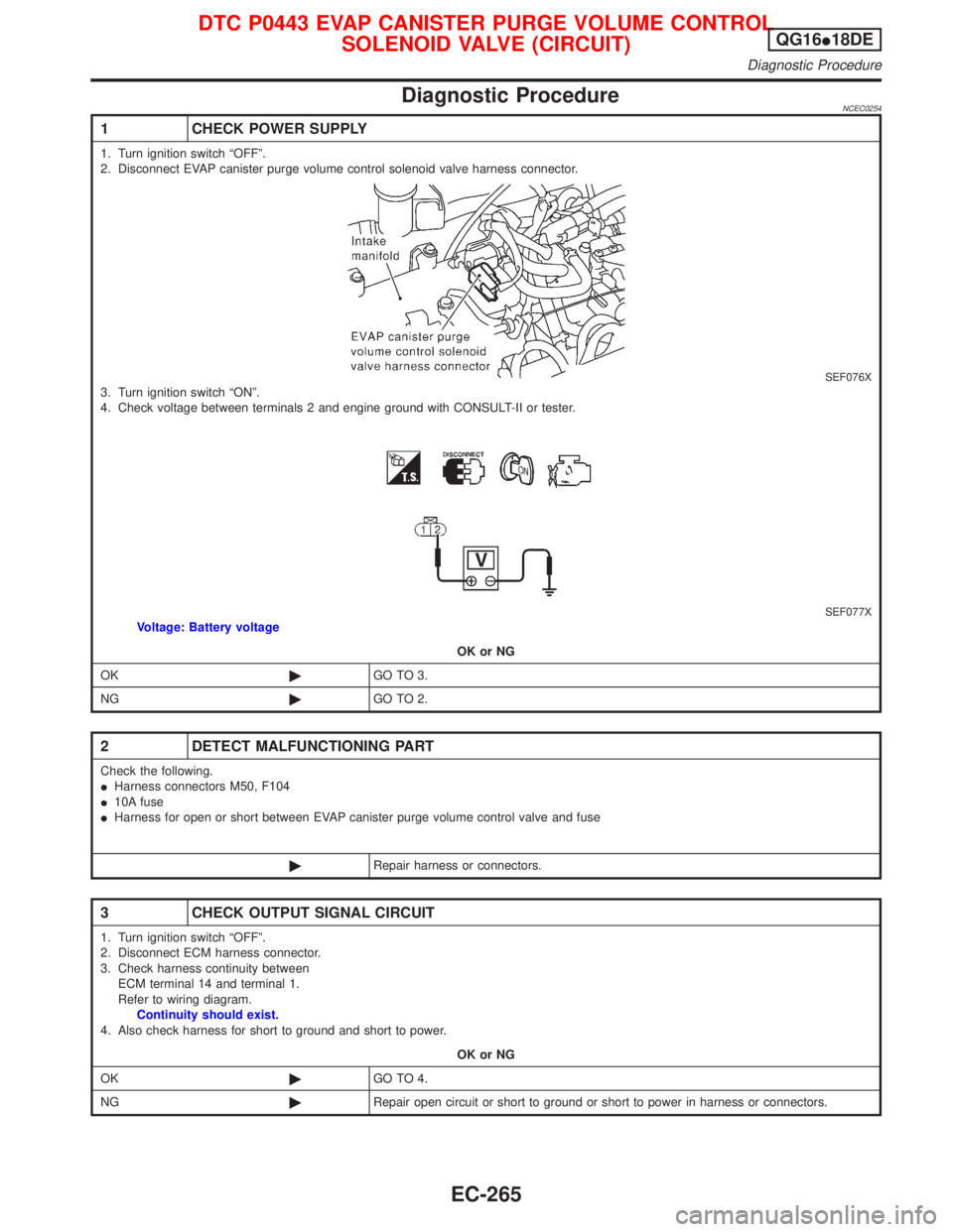
1 CHECK POWER SUPPLY
1. Turn ignition switch ªOFFº.
2. Disconnect EVAP canister purge volume control solenoid valve harness connector.
SEF076X3. Turn ignition switch ªONº.
4. Check voltage between terminals 2 and engine ground with CONSULT-II or tester.
SEF077XVoltage: Battery voltage
OK or NG
OK©GO TO 3.
NG©GO TO 2.
2 DETECT MALFUNCTIONING PART
Check the following.
IHarness connectors M50, F104
I10A fuse
IHarness for open or short between EVAP canister purge volume control valve and fuse
©Repair harness or connectors.
3 CHECK OUTPUT SIGNAL CIRCUIT
1. Turn ignition switch ªOFFº.
2. Disconnect ECM harness connector.
3. Check harness continuity between
ECM terminal 14 and terminal 1.
Refer to wiring diagram.
Continuity should exist.
4. Also check harness for short to ground and short to power.
OK or NG
OK©GO TO 4.
NG©Repair open circuit or short to ground or short to power in harness or connectors.
DTC P0443 EVAP CANISTER PURGE VOLUME CONTROL
SOLENOID VALVE (CIRCUIT)QG16I18DE
Diagnostic Procedure
EC-265
Page 711 of 2267
Wiring DiagramNCEC0277MODELS BEFORE VIN - P11U0548750
YEC784
IGNITION SWITCH
ON or START
Refer to EL-POWER.: Detectable line for DTC
: Non-detectable line for DTC FUSE
BLOCK
(J/B)
COMBINATION
METER
(SPEEDOMETER)
ECM
Refer to last page (Foldout page) VEHICLE
SPEED
SENSOR BATTERY
DTC P0500 VEHICLE SPEED SENSOR (VSS)QG16I18DE
Wiring Diagram
EC-269
Page 719 of 2267

Diagnostic ProcedureNCEC0285
1 CHECK POWER SUPPLY
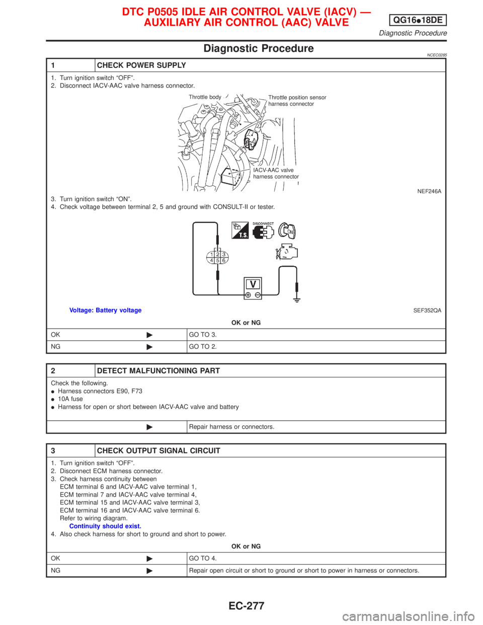
1. Turn ignition switch ªOFFº.
2. Disconnect IACV-AAC valve harness connector.
NEF246A3. Turn ignition switch ªONº.
4. Check voltage between terminal 2, 5 and ground with CONSULT-II or tester.
SEF352QAVoltage: Battery voltage
OK or NG
OK©GO TO 3.
NG©GO TO 2.
2 DETECT MALFUNCTIONING PART
Check the following.
IHarness connectors E90, F73
I10A fuse
IHarness for open or short between IACV-AAC valve and battery
©Repair harness or connectors.
3 CHECK OUTPUT SIGNAL CIRCUIT
1. Turn ignition switch ªOFFº.
2. Disconnect ECM harness connector.
3. Check harness continuity between
ECM terminal 6 and IACV-AAC valve terminal 1,
ECM terminal 7 and IACV-AAC valve terminal 4,
ECM terminal 15 and IACV-AAC valve terminal 3,
ECM terminal 16 and IACV-AAC valve terminal 6.
Refer to wiring diagram.
Continuity should exist.
4. Also check harness for short to ground and short to power.
OK or NG
OK©GO TO 4.
NG©Repair open circuit or short to ground or short to power in harness or connectors.
Throttle body
Throttle position sensor
harness connector
IACV-AAC valve
harness connector
DTC P0505 IDLE AIR CONTROL VALVE (IACV) Ð
AUXILIARY AIR CONTROL (AAC) VALVEQG16I18DE
Diagnostic Procedure
EC-277
Page 728 of 2267
Wiring DiagramNCEC0519
YEC787
: Detectable line for DTC
: Non-detectable line for DTC
ECM INTAKE VALVE
TIMING CONTROL
SOLENOID
VA LV EFUSE
BLOCK
(J/B)Refer to
EL-POWER. IGNITION SWITCH
ON or START
Refer to last page (Foldout page)
.IVC
D T C P 1111 I N TA K E VA LV ETIMING CONTROL
SOLENOID VALVEQG16I18DE
Wiring Diagram
EC-286