Page 471 of 2267

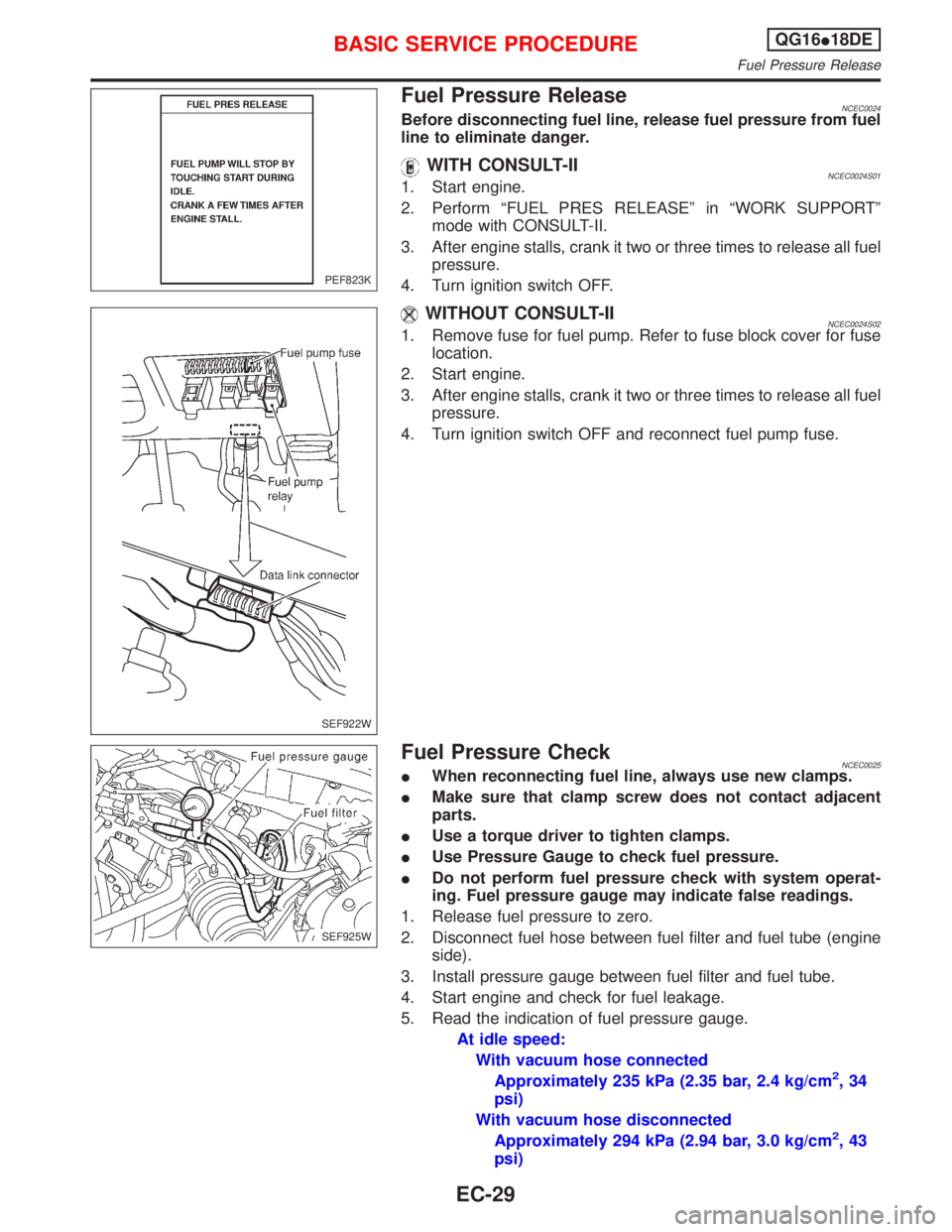
Fuel Pressure ReleaseNCEC0024Before disconnecting fuel line, release fuel pressure from fuel
line to eliminate danger.
WITH CONSULT-IINCEC0024S011. Start engine.
2. Perform ªFUEL PRES RELEASEº in ªWORK SUPPORTº
mode with CONSULT-II.
3. After engine stalls, crank it two or three times to release all fuel
pressure.
4. Turn ignition switch OFF.
WITHOUT CONSULT-IINCEC0024S021. Remove fuse for fuel pump. Refer to fuse block cover for fuse
location.
2. Start engine.
3. After engine stalls, crank it two or three times to release all fuel
pressure.
4. Turn ignition switch OFF and reconnect fuel pump fuse.
Fuel Pressure CheckNCEC0025IWhen reconnecting fuel line, always use new clamps.
IMake sure that clamp screw does not contact adjacent
parts.
IUse a torque driver to tighten clamps.
IUse Pressure Gauge to check fuel pressure.
IDo not perform fuel pressure check with system operat-
ing. Fuel pressure gauge may indicate false readings.
1. Release fuel pressure to zero.
2. Disconnect fuel hose between fuel filter and fuel tube (engine
side).
3. Install pressure gauge between fuel filter and fuel tube.
4. Start engine and check for fuel leakage.
5. Read the indication of fuel pressure gauge.
At idle speed:
With vacuum hose connected
Approximately 235 kPa (2.35 bar, 2.4 kg/cm
2,34
psi)
With vacuum hose disconnected
Approximately 294 kPa (2.94 bar, 3.0 kg/cm
2,43
psi)
PEF823K
SEF922W
SEF925W
BASIC SERVICE PROCEDUREQG16I18DE
Fuel Pressure Release
EC-29
Page 477 of 2267
IEngine stalls.
IErroneous idle.
IBlown fuses related to IACV-AAC valve system.
BASIC SERVICE PROCEDUREQG16I18DE
Idle Air Volume Learning (Cont'd)
EC-35
Page 497 of 2267
CONSULT-II=NCEC0034CONSULT-II INSPECTION PROCEDURENCEC0034S011. Turn ignition switch OFF.
2. Connect ªCONSULT-IIº to data link connector.
(Data link connector is located behind the fuse box cover.)
3. Turn ignition switch ON.
4. Touch ªSTARTº.
5. Touch ªENGINEº.
6. Perform each diagnostic test mode according to each service
procedure.
For further information, see the CONSULT-II Operation
Manual.
SEF922W
PBR455D
PEF895K
NEF244A
ON BOARD DIAGNOSTIC SYSTEM DESCRIPTIONQG16I18DE
CONSULT-II
EC-55
Page 508 of 2267
Generic Scan Tool (GST)=NCEC0035DESCRIPTIONNCEC0035S01Generic Scan Tool (OBDII scan tool) complying with ISO15031-4
has 9 different functions explained on the next page.
ISO9141 is used as the protocol.
The name ªGSTº or ªGeneric Scan Toolº is used in this service
manual.
GST INSPECTION PROCEDURENCEC0035S021. Turn ignition switch OFF.
2. Connect ªGSTº to data link connector. (Data link connector is
located under the fuse box cover.)
3. Turn ignition switch ON.
4. Enter the program according to instruction on the screen or in
the operation manual.
(*: Regarding GST screens in this section, sample screens are
shown.)
5. Perform each diagnostic mode according to each service pro-
cedure.
For further information, see the GST Operation Manual of the
tool maker.
SEF139P
SEF922W
SEF398S
SEF416S
ON BOARD DIAGNOSTIC SYSTEM DESCRIPTIONQG16I18DE
Generic Scan Tool (GST)
EC-66
Page 545 of 2267
Main Power Supply and Ground Circuit
WIRING DIAGRAMNCEC0047
YEC770
BATTERY
Refer to EL-POWER.
OFF
ACCST
ONIGNITION
SWITCH
FUSE
BLOCK
(J/B)
To EC-IGN/SG,
EC-TP/SW,
EC-AAC/V,
EC-EGR,
EC-EGVC/V ECM RELAY
: Detectable line for DTC
: Non-detectable line for DTC
Refer to last page (Foldout page) ECM
TROUBLE DIAGNOSIS FOR POWER SUPPLYQG16I18DE
Main Power Supply and Ground Circuit
EC-103
Page 547 of 2267
2 CHECK POWER SUPPLY-I
1. Turn ignition switch ªOFFº and then ªONº.
2. Check voltage between ECM terminal 43 and ground with CONSULT-II or tester.
SEF981WVoltage: Battery voltage
OK or NG
OK©GO TO 9.
NG©GO TO 3.
3 DETECT MALFUNCTIONING PART
Check the following.
I10A Fuse
I40A fusible link
IHarness connectors M50, F104
IHarness for open or short between ECM and fuse block
IHarness for open or short between fuse block and ignition switch
©Repair harness or connectors.
4 CHECK ECM GROUND CIRCUIT FOR OPEN AND SHORT-I
1. Turn ignition switch ªOFFº.
2. Disconnect ECM harness connector.
3. Check harness continuity between ECM terminals 48, 57, 106, 108 and engine ground.
Refer to WIRING DIAGRAM.
Continuity should exist.
4. Also check harness for short to power.
OK or NG
OK©GO TO 5.
NG©Repair open circuit or short to power in harness or connectors.
TROUBLE DIAGNOSIS FOR POWER SUPPLYQG16I18DE
Main Power Supply and Ground Circuit (Cont'd)
EC-105
Page 548 of 2267
5 CHECK POWER SUPPLY-II
1. Disconnect ECM relay.
SEF984W
2. Check voltage between ECM relay terminals 1, 6 and ground with CONSULT-II or tester.
SEF101Y
OK or NG
OK©GO TO 7.
NG©GO TO 6.
6 DETECT MALFUNCTIONING PART
Check the following.
I10A fuse
I15A fuse
IHarness for open or short between ECM relay and battery
©Repair open circuit or short to ground or short to power in harness or connectors.
7 CHECK OUTPUT SIGNAL CIRCUIT FOR OPEN AND SHORT
1. Check harness continuity between ECM terminal 31 and ECM relay terminal 2.
Continuity should exist.
2. Also check harness for short to ground and short to power.
OK or NG
OK©Go to ªIGNITION SIGNALº, EC-QG-323.
NG©GO TO 8.
8 DETECT MALFUNCTIONING PART
Check the harness for open or short between ECM relay and ECM.
©Repair open circuit or short to ground or short to power in harness or connectors.
TROUBLE DIAGNOSIS FOR POWER SUPPLYQG16I18DE
Main Power Supply and Ground Circuit (Cont'd)
EC-106
Page 549 of 2267
9 CHECK POWER SUPPLY-II
1. Stop engine.
2. Check voltage between ECM terminals 67 and ground with CONSULT-II or tester.
SEF982WVoltage: Battery voltage
OK or NG
OK©GO TO 11.
NG©GO TO 10.
10 DETECT MALFUNCTIONING PART
Check the following.
IHarness connectors E90, F73
I10A fuse
IHarness for open or short between ECM and fuse
©Repair harness or connectors.
11 CHECK POWER SUPPLY-III
1. Turn ignition switch ªONº and then ªOFFº.
2. Check voltage between ECM terminals 110, 112 and ground with CONSULT-II or tester.
SEF983WVoltage:
After turning ignition switch ªOFFº, battery voltage will exist for a few seconds, then drop to approximately 0V.
OK or NG
OK©GO TO 17.
NG (Battery voltage does not
exist.)©GO TO 12.
NG (Battery voltage exists for
more than a few seconds.)©GO TO 16.
TROUBLE DIAGNOSIS FOR POWER SUPPLYQG16I18DE
Main Power Supply and Ground Circuit (Cont'd)
EC-107