1999 NISSAN PRIMERA light
[x] Cancel search: lightPage 1638 of 2267
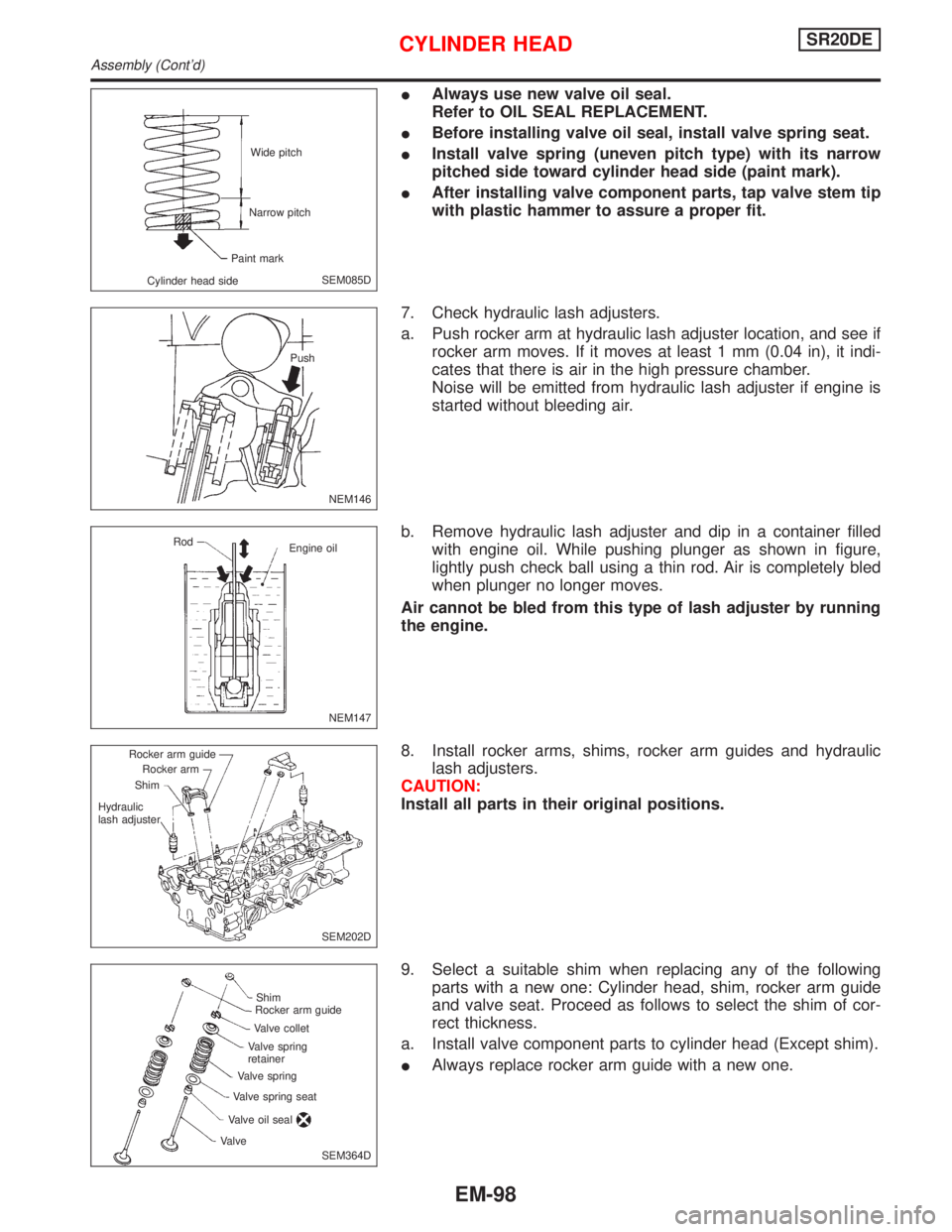
IAlways use new valve oil seal.
Refer to OIL SEAL REPLACEMENT.
IBefore installing valve oil seal, install valve spring seat.
IInstall valve spring (uneven pitch type) with its narrow
pitched side toward cylinder head side (paint mark).
IAfter installing valve component parts, tap valve stem tip
with plastic hammer to assure a proper fit.
7. Check hydraulic lash adjusters.
a. Push rocker arm at hydraulic lash adjuster location, and see if
rocker arm moves. If it moves at least 1 mm (0.04 in), it indi-
cates that there is air in the high pressure chamber.
Noise will be emitted from hydraulic lash adjuster if engine is
started without bleeding air.
b. Remove hydraulic lash adjuster and dip in a container filled
with engine oil. While pushing plunger as shown in figure,
lightly push check ball using a thin rod. Air is completely bled
when plunger no longer moves.
Air cannot be bled from this type of lash adjuster by running
the engine.
8. Install rocker arms, shims, rocker arm guides and hydraulic
lash adjusters.
CAUTION:
Install all parts in their original positions.
9. Select a suitable shim when replacing any of the following
parts with a new one: Cylinder head, shim, rocker arm guide
and valve seat. Proceed as follows to select the shim of cor-
rect thickness.
a. Install valve component parts to cylinder head (Except shim).
IAlways replace rocker arm guide with a new one.
SEM085D Wide pitch
Narrow pitch
Paint mark
Cylinder head side
NEM146 Push
NEM147 Rod
Engine oil
SEM202D Rocker arm guide
Rocker arm
Shim
Hydraulic
lash adjuster
SEM364D Shim
Rocker arm guide
Valve collet
Valve spring
retainer
Valve spring
Valve spring seat
Valve oil sealValve
CYLINDER HEADSR20DE
Assembly (Cont'd)
EM-98
Page 1639 of 2267
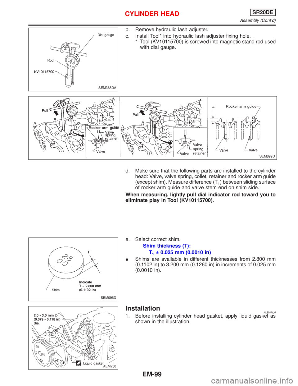
b. Remove hydraulic lash adjuster.
c. Install Tool* into hydraulic lash adjuster fixing hole.
* Tool (KV10115700) is screwed into magnetic stand rod used
with dial gauge.
d. Make sure that the following parts are installed to the cylinder
head: Valve, valve spring, collet, retainer and rocker arm guide
(except shim). Measure difference (T
1) between sliding surface
of rocker arm guide and valve stem end on shim side.
When measuring, lightly pull dial indicator rod toward you to
eliminate play in Tool (KV10115700).
e. Select correct shim.
Shim thickness (T):
T
1 0.025 mm (0.0010 in)
IShims are available in different thicknesses from 2.800 mm
(0.1102 in) to 3.200 mm (0.1260 in) in increments of 0.025 mm
(0.0010 in).
InstallationNLEM01361. Before installing cylinder head gasket, apply liquid gasket as
shown in the illustration.
SEM365DA Dial gauge
Rod
SEM899D
SEM096D ShimIndicate
T=2.800 mm
(0.1102 in)
AEM250 2.0 - 3.0 mm
(0.079 - 0.118 in)
dia.Liquid gasket
CYLINDER HEADSR20DE
Assembly (Cont'd)
EM-99
Page 1757 of 2267
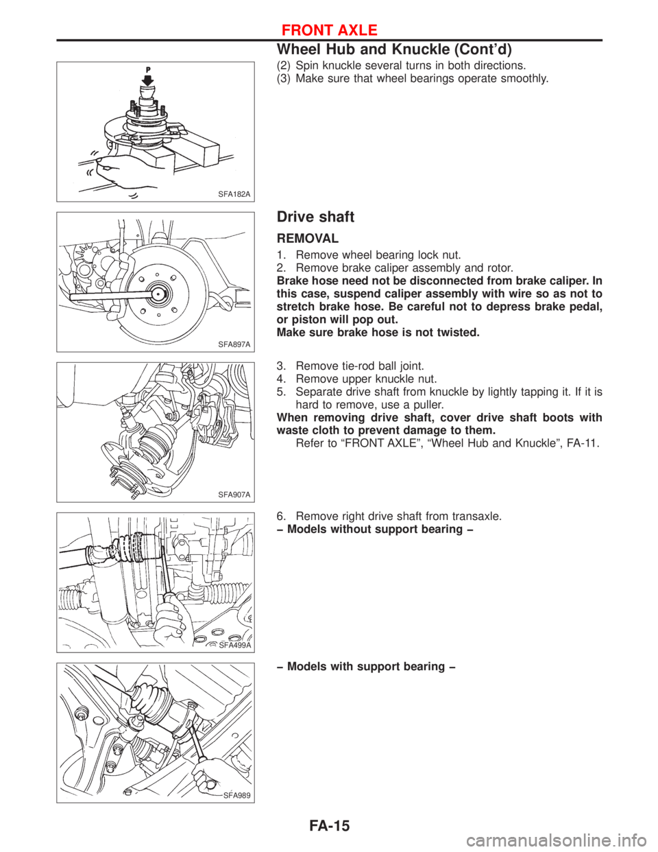
(2) Spin knuckle several turns in both directions.
(3) Make sure that wheel bearings operate smoothly.
Drive shaft
REMOVAL
1. Remove wheel bearing lock nut.
2. Remove brake caliper assembly and rotor.
Brake hose need not be disconnected from brake caliper. In
this case, suspend caliper assembly with wire so as not to
stretch brake hose. Be careful not to depress brake pedal,
or piston will pop out.
Make sure brake hose is not twisted.
3. Remove tie-rod ball joint.
4. Remove upper knuckle nut.
5. Separate drive shaft from knuckle by lightly tapping it. If it is
hard to remove, use a puller.
When removing drive shaft, cover drive shaft boots with
waste cloth to prevent damage to them.
Refer to ªFRONT AXLEº, ªWheel Hub and Knuckleº, FA-11.
6. Remove right drive shaft from transaxle.
þ Models without support bearing þ
þ Models with support bearing þ
SFA182A
SFA897A
SFA907A
.SFA499A
.SFA989
FRONT AXLE
Wheel Hub and Knuckle (Cont'd)
FA-15
Page 1764 of 2267
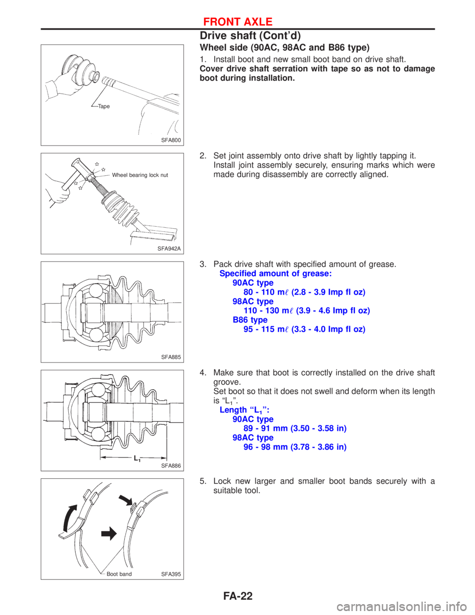
Wheel side (90AC, 98AC and B86 type)
1. Install boot and new small boot band on drive shaft.
Cover drive shaft serration with tape so as not to damage
boot during installation.
2. Set joint assembly onto drive shaft by lightly tapping it.
Install joint assembly securely, ensuring marks which were
made during disassembly are correctly aligned.
3. Pack drive shaft with specified amount of grease.
Specified amount of grease:
90AC type
80 - 110 m(2.8 - 3.9 Imp fl oz)
98AC type
110 - 130 m(3.9 - 4.6 Imp fl oz)
B86 type
95 - 115 m(3.3 - 4.0 Imp fl oz)
4. Make sure that boot is correctly installed on the drive shaft
groove.
Set boot so that it does not swell and deform when its length
is ªL
1º.
Length ªL
1º:
90AC type
89 - 91 mm (3.50 - 3.58 in)
98AC type
96 - 98 mm (3.78 - 3.86 in)
5. Lock new larger and smaller boot bands securely with a
suitable tool.
SFA800 Tape
SFA942A Wheel bearing lock nut
SFA885
SFA886L1
SFA395 Boot band
FRONT AXLE
Drive shaft (Cont'd)
FA-22
Page 1808 of 2267
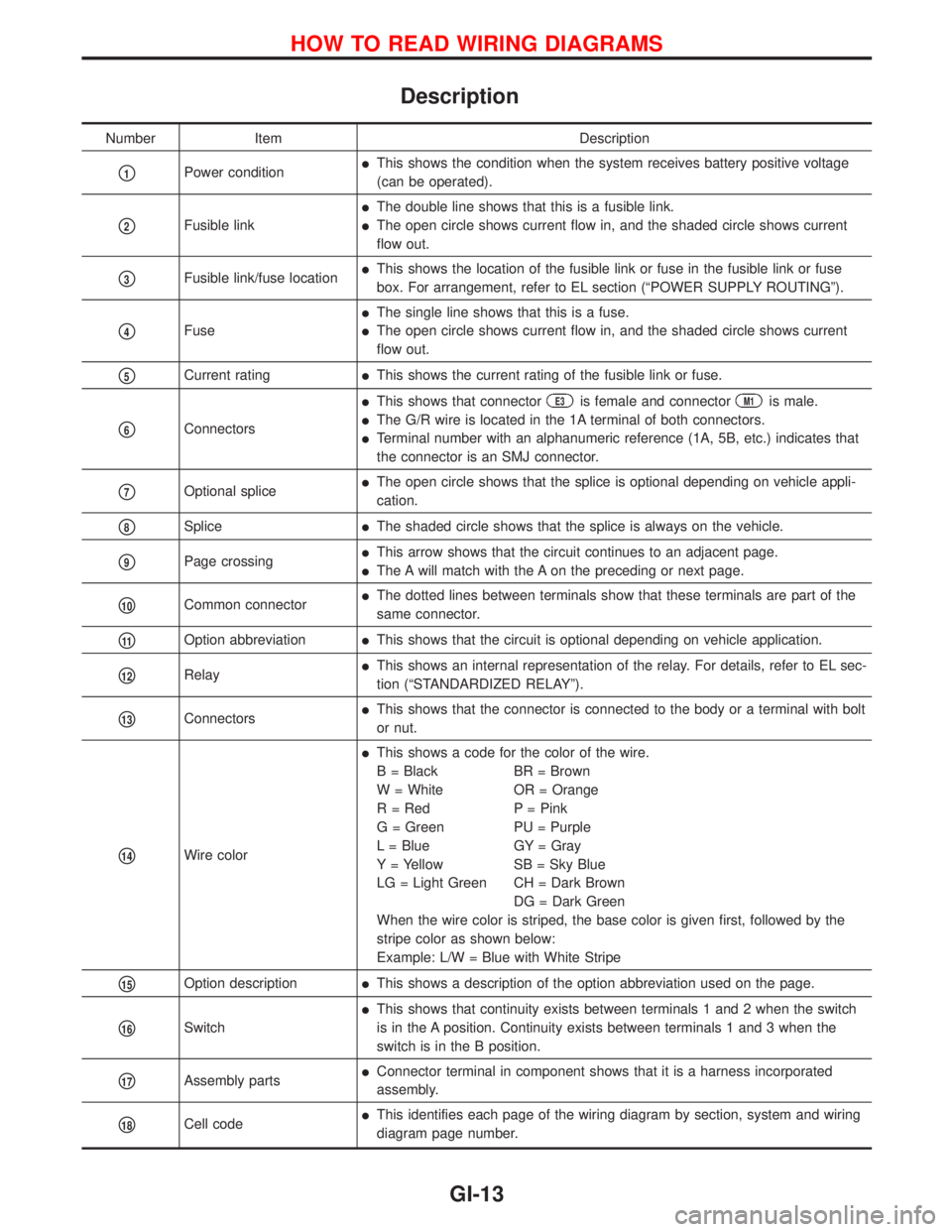
Description
Number Item Description
p1Power conditionlThis shows the condition when the system receives battery positive voltage
(can be operated).
p2Fusible link
lThe double line shows that this is a fusible link.
lThe open circle shows current flow in, and the shaded circle shows current
flow out.
p3Fusible link/fuse locationlThis shows the location of the fusible link or fuse in the fusible link or fuse
box. For arrangement, refer to EL section (ªPOWER SUPPLY ROUTINGº).
p4Fuse
lThe single line shows that this is a fuse.
lThe open circle shows current flow in, and the shaded circle shows current
flow out.
p5Current ratinglThis shows the current rating of the fusible link or fuse.
p6Connectors
lThis shows that connectorE3is female and connectorM1is male.
lThe G/R wire is located in the 1A terminal of both connectors.
lTerminal number with an alphanumeric reference (1A, 5B, etc.) indicates that
the connector is an SMJ connector.
p7Optional splicelThe open circle shows that the splice is optional depending on vehicle appli-
cation.
p8SplicelThe shaded circle shows that the splice is always on the vehicle.
p9Page crossinglThis arrow shows that the circuit continues to an adjacent page.
lThe A will match with the A on the preceding or next page.
p10Common connectorlThe dotted lines between terminals show that these terminals are part of the
same connector.
p11Option abbreviationlThis shows that the circuit is optional depending on vehicle application.
p12RelaylThis shows an internal representation of the relay. For details, refer to EL sec-
tion (ªSTANDARDIZED RELAYº).
p13ConnectorslThis shows that the connector is connected to the body or a terminal with bolt
or nut.
p14Wire color
lThis shows a code for the color of the wire.
B = Black BR = Brown
W = White OR = Orange
R = Red P = Pink
G = Green PU = Purple
L = Blue GY = Gray
Y = Yellow SB = Sky Blue
LG = Light Green CH = Dark Brown
DG = Dark Green
When the wire color is striped, the base color is given first, followed by the
stripe color as shown below:
Example: L/W = Blue with White Stripe
p15Option descriptionlThis shows a description of the option abbreviation used on the page.
p16Switch
lThis shows that continuity exists between terminals 1 and 2 when the switch
is in the A position. Continuity exists between terminals 1 and 3 when the
switch is in the B position.
p17Assembly partslConnector terminal in component shows that it is a harness incorporated
assembly.
p18Cell codelThis identifies each page of the wiring diagram by section, system and wiring
diagram page number.
HOW TO READ WIRING DIAGRAMS
GI-13
Page 1815 of 2267
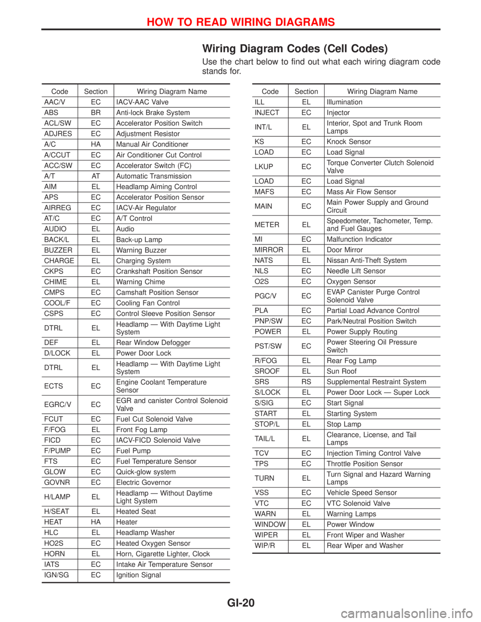
Wiring Diagram Codes (Cell Codes)
Use the chart below to find out what each wiring diagram code
stands for.
Code Section Wiring Diagram Name
AAC/V EC IACV-AAC Valve
ABS BR Anti-lock Brake System
ACL/SW EC Accelerator Position Switch
ADJRES EC Adjustment Resistor
A/C HA Manual Air Conditioner
A/CCUT EC Air Conditioner Cut Control
ACC/SW EC Accelerator Switch (FC)
A/T AT Automatic Transmission
AIM EL Headlamp Aiming Control
APS EC Accelerator Position Sensor
AIRREG EC IACV-Air Regulator
AT/C EC A/T Control
AUDIO EL Audio
BACK/L EL Back-up Lamp
BUZZER EL Warning Buzzer
CHARGE EL Charging System
CKPS EC Crankshaft Position Sensor
CHIME EL Warning Chime
CMPS EC Camshaft Position Sensor
COOL/F EC Cooling Fan Control
CSPS EC Control Sleeve Position Sensor
DTRL ELHeadlamp Ð With Daytime Light
System
DEF EL Rear Window Defogger
D/LOCK EL Power Door Lock
DTRL ELHeadlamp Ð With Daytime Light
System
ECTS ECEngine Coolant Temperature
Sensor
EGRC/V ECEGR and canister Control Solenoid
Valve
FCUT EC Fuel Cut Solenoid Valve
F/FOG EL Front Fog Lamp
FICD EC IACV-FICD Solenoid Valve
F/PUMP EC Fuel Pump
FTS EC Fuel Temperature Sensor
GLOW EC Quick-glow system
GOVNR EC Electric Governor
H/LAMP ELHeadlamp Ð Without Daytime
Light System
H/SEAT EL Heated Seat
HEAT HA Heater
HLC EL Headlamp Washer
HO2S EC Heated Oxygen Sensor
HORN EL Horn, Cigarette Lighter, Clock
IATS EC Intake Air Temperature Sensor
IGN/SG EC Ignition SignalCode Section Wiring Diagram Name
ILL EL Illumination
INJECT EC Injector
INT/L ELInterior, Spot and Trunk Room
Lamps
KS EC Knock Sensor
LOAD EC Load Signal
LKUP ECTorque Converter Clutch Solenoid
Valve
LOAD EC Load Signal
MAFS EC Mass Air Flow Sensor
MAIN ECMain Power Supply and Ground
Circuit
METER ELSpeedometer, Tachometer, Temp.
and Fuel Gauges
MI EC Malfunction Indicator
MIRROR EL Door Mirror
NATS EL Nissan Anti-Theft System
NLS EC Needle Lift Sensor
O2S EC Oxygen Sensor
PGC/V ECEVAP Canister Purge Control
Solenoid Valve
PLA EC Partial Load Advance Control
PNP/SW EC Park/Neutral Position Switch
POWER EL Power Supply Routing
PST/SW ECPower Steering Oil Pressure
Switch
R/FOG EL Rear Fog Lamp
SROOF EL Sun Roof
SRS RS Supplemental Restraint System
S/LOCK EL Power Door Lock Ð Super Lock
S/SIG EC Start Signal
START EL Starting System
STOP/L EL Stop Lamp
TAIL/L ELClearance, License, and Tail
Lamps
TCV EC Injection Timing Control Valve
TPS EC Throttle Position Sensor
TURN ELTurn Signal and Hazard Warning
Lamps
VSS EC Vehicle Speed Sensor
VTC EC VTC Solenoid Valve
WARN EL Warning Lamps
WINDOW EL Power Window
WIPER EL Front Wiper and Washer
WIP/R EL Rear Wiper and Washer
HOW TO READ WIRING DIAGRAMS
GI-20
Page 1820 of 2267
Incident Simulation Tests
INTRODUCTION
Sometimes the symptom is not present when the vehicle is brought in for service. If possible, re-create the
conditions present at the time of the incident. Doing so may help avoid a No Trouble Found Diagnosis. The
following section illustrates ways to simulate the conditions/environment under which the owner experiences
an electrical incident.
The section is broken into the six following topics:
lVehicle vibration
lHeat sensitive
lFreezing
lWater intrusion
lElectrical load
lCold or hot start up
Get a thorough description of the incident from the customer. It is important for simulating the conditions of
the problem.
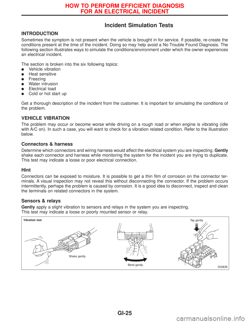
VEHICLE VIBRATION
The problem may occur or become worse while driving on a rough road or when engine is vibrating (idle
with A/C on). In such a case, you will want to check for a vibration related condition. Refer to the illustration
below.
Connectors & harness
Determine which connectors and wiring harness would affect the electrical system you are inspecting.Gently
shake each connector and harness while monitoring the system for the incident you are trying to duplicate.
This test may indicate a loose or poor electrical connection.
Hint
Connectors can be exposed to moisture. It is possible to get a thin film of corrosion on the connector ter-
minals. A visual inspection may not reveal this without disconnecting the connector. If the problem occurs
intermittently, perhaps the problem is caused by corrosion. It is a good idea to disconnect, inspect and clean
the terminals on related connectors in the system.
Sensors & relays
Gentlyapply a slight vibration to sensors and relays in the system you are inspecting.
This test may indicate a loose or poorly mounted sensor or relay.
SGI839 Vibration test
Shake gently.
Bend gently.Tap gently.
HOW TO PERFORM EFFICIENT DIAGNOSIS
FOR AN ELECTRICAL INCIDENT
GI-25
Page 1823 of 2267
FREEZING
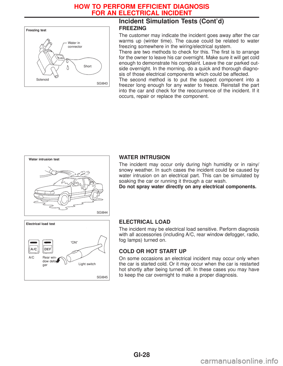
The customer may indicate the incident goes away after the car
warms up (winter time). The cause could be related to water
freezing somewhere in the wiring/electrical system.
There are two methods to check for this. The first is to arrange
for the owner to leave his car overnight. Make sure it will get cold
enough to demonstrate his complaint. Leave the car parked out-
side overnight. In the morning, do a quick and thorough diagno-
sis of those electrical components which could be affected.
The second method is to put the suspect component into a
freezer long enough for any water to freeze. Reinstall the part
into the car and check for the reoccurrence of the incident. If it
occurs, repair or replace the component.
WATER INTRUSION
The incident may occur only during high humidity or in rainy/
snowy weather. In such cases the incident could be caused by
water intrusion on an electrical part. This can be simulated by
soaking the car or running it through a car wash.
Do not spray water directly on any electrical components.
ELECTRICAL LOAD
The incident may be electrical load sensitive. Perform diagnosis
with all accessories (including A/C, rear window defogger, radio,
fog lamps) turned on.
COLD OR HOT START UP
On some occasions an electrical incident may occur only when
the car is started cold. Or it may occur when the car is restarted
hot shortly after being turned off. In these cases you may have
to keep the car overnight to make a proper diagnosis.
SGI843 Freezing test
Water in
connector
SolenoidShort
SGI844
Water intrusion test
SGI845 Electrical load test
ªONº
Rear win-
dow defog-
gerLight switch A/C
HOW TO PERFORM EFFICIENT DIAGNOSIS
FOR AN ELECTRICAL INCIDENT
Incident Simulation Tests (Cont'd)
GI-28