Page 2063 of 2267
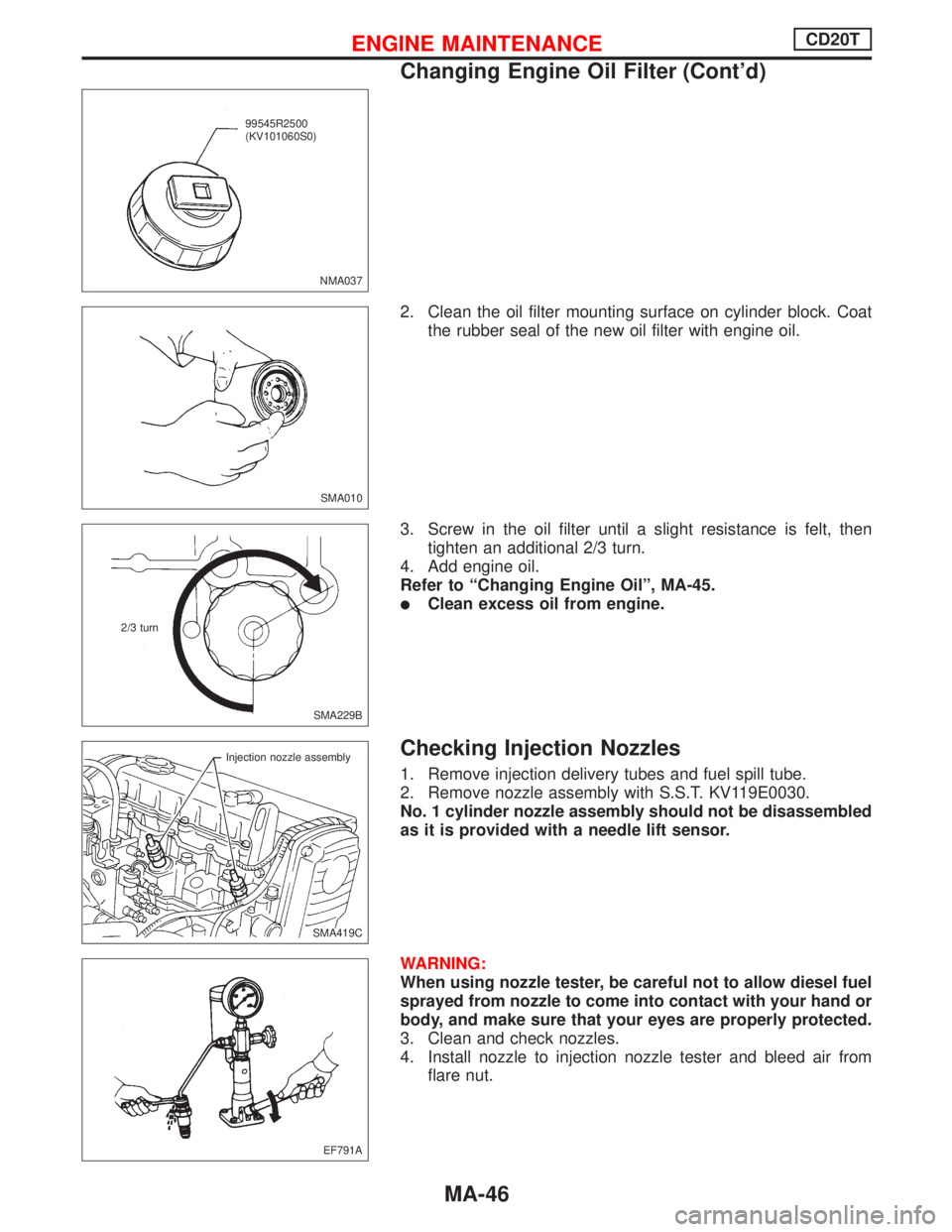
2. Clean the oil filter mounting surface on cylinder block. Coat
the rubber seal of the new oil filter with engine oil.
3. Screw in the oil filter until a slight resistance is felt, then
tighten an additional 2/3 turn.
4. Add engine oil.
Refer to“Changing Engine Oil”, MA-45.
�Clean excess oil from engine.
Checking Injection Nozzles
1. Remove injection delivery tubes and fuel spill tube.
2. Remove nozzle assembly with S.S.T. KV119E0030.
No. 1 cylinder nozzle assembly should not be disassembled
as it is provided with a needle lift sensor.
WARNING:
When using nozzle tester, be careful not to allow diesel fuel
sprayed from nozzle to come into contact with your hand or
body, and make sure that your eyes are properly protected.
3. Clean and check nozzles.
4. Install nozzle to injection nozzle tester and bleed air from
flare nut.
NMA037
.99545R2500
(KV101060S0)
SMA010
SMA229B 2/3 turn
SMA419C Injection nozzle assembly
EF791A
ENGINE MAINTENANCECD20T
Changing Engine Oil Filter (Cont’d)
MA-46
Page 2095 of 2267
1. Remove case cover.
2. Remove mainshaft bearing snap ring.
3. Remove transmission case while slightly tilting it to prevent 5th
shift fork from interfering with case.
4. Draw out reverse idler spacer and fork shaft.
5. Remove 5th and 3rd & 4th shift forks.
IBe careful not to lose shifter cap.
SMT664B Case cover
SMT665B Snap ring
SMT666B
SMT667B Fork shaft
SMT188A 5th
shift
fork
3rd & 4th
shift fork
DISASSEMBLYRS5F32A
MT-18
Page 2117 of 2267
9. Install selected shim and differential side bearing outer race.
10. Check differential side bearing turning torque.
a. Install final drive assembly on clutch housing.
b. Install transmission case on clutch housing.
ITighten transmission case fixing bolts to the specified
torque. Page MT-15
c. Measure turning torque of final drive assembly.
Turning torque of final drive assembly
(New bearing):
2.9 - 6.9 N´m (30 - 70 kg-cm, 26 - 61 in-lb)
IWhen old bearing is used again, turning torque will be
slightly less than the above.
IMake sure torque is close to the specified range.
IChanges in turning torque of final drive assembly per
revolution should be within 1.0 N´m (10 kg-cm, 8.7 in-lb)
without binding.
SMT600 KV38107700
ADJUSTMENTRS5F32A
Differential Side Bearing Preload (Cont'd)
MT-40
Page 2158 of 2267
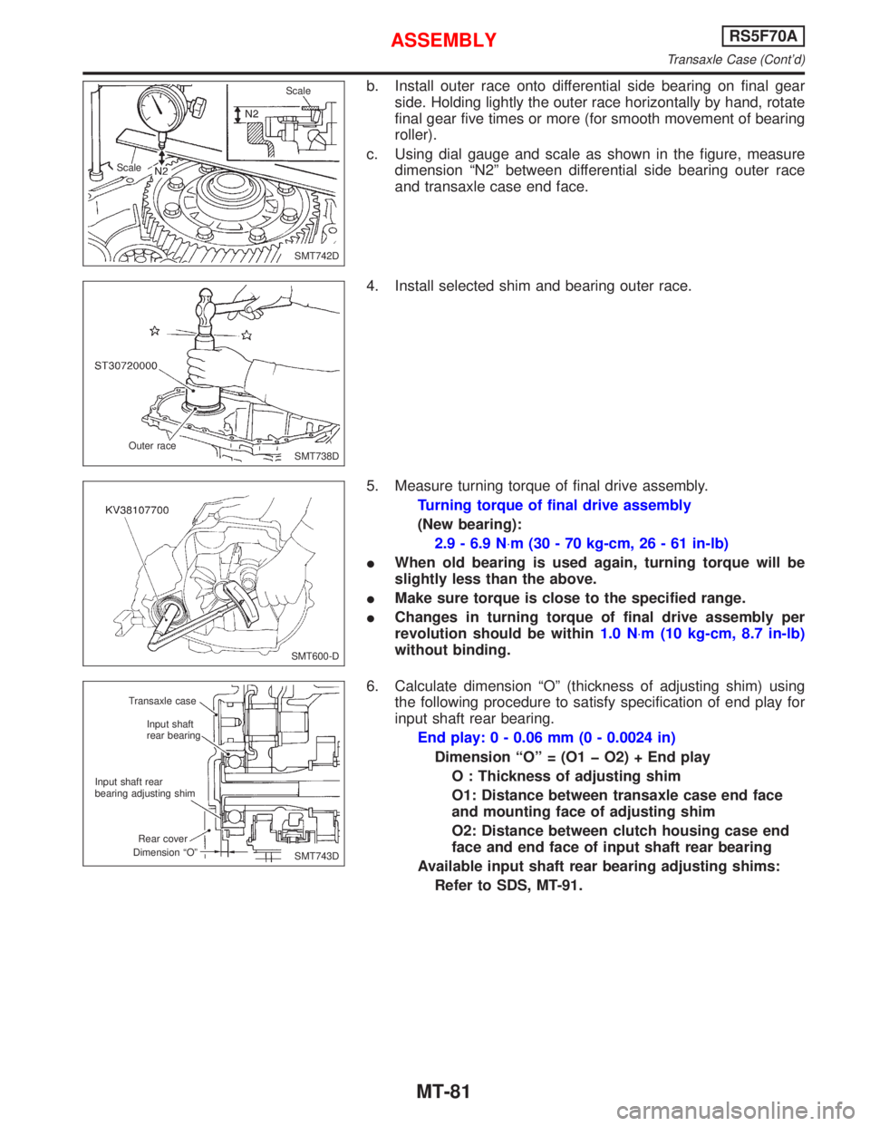
b. Install outer race onto differential side bearing on final gear
side. Holding lightly the outer race horizontally by hand, rotate
final gear five times or more (for smooth movement of bearing
roller).
c. Using dial gauge and scale as shown in the figure, measure
dimension ªN2º between differential side bearing outer race
and transaxle case end face.
4. Install selected shim and bearing outer race.
5. Measure turning torque of final drive assembly.
Turning torque of final drive assembly
(New bearing):
2.9 - 6.9 N×m (30 - 70 kg-cm, 26 - 61 in-lb)
IWhen old bearing is used again, turning torque will be
slightly less than the above.
IMake sure torque is close to the specified range.
IChanges in turning torque of final drive assembly per
revolution should be within1.0 N×m (10 kg-cm, 8.7 in-lb)
without binding.
6. Calculate dimension ªOº (thickness of adjusting shim) using
the following procedure to satisfy specification of end play for
input shaft rear bearing.
End play: 0 - 0.06 mm (0 - 0.0024 in)
Dimension ªOº = (O1 þ O2) + End play
O : Thickness of adjusting shim
O1: Distance between transaxle case end face
and mounting face of adjusting shim
O2: Distance between clutch housing case end
face and end face of input shaft rear bearing
Available input shaft rear bearing adjusting shims:
Refer to SDS, MT-91.
SMT742D ScaleScale
SMT738D Outer race
SMT600-D
SMT743D Transaxle case
Input shaft
rear bearing
Input shaft rear
bearing adjusting shim
Rear cover
Dimension ªOº
ASSEMBLYRS5F70A
Transaxle Case (Cont'd)
MT-81
Page 2205 of 2267
Disposal of Air Bag Module and Seat Belt
Pre-tensioner
lBefore disposing of air bag module and seat belt pre-tensioner, or vehicles equipped with such systems,
deploy the systems. If such systems have already been deployed due to an accident, dispose of as
indicated in ªDISPOSING OF AIR BAG MODULE AND SEAT BELT PRE-TENSIONERº (RS-27).
lWhen deploying the air bag module and seat belt pre-tensioner, always use the Special Service Tool;
Deployment tool KV99106400.
lWhen deploying the air bag module and seat belt pre-tensioner, stand at least 5 m (16 ft) away from
deployment component.
lWhen deploying air bag module and seat belt pre-tensioner a fairly loud noise is made, followed by
smoke being released. The smoke is not poisonous, however, be careful not to inhale smoke since it
irritates the throat and can cause choking.
lAlways activate one air bag module at a time.
lDue to heat, leave air bag module unattended for more than 30 minutes after deployment. Also leave
seat belt pre-tensioner unattended for more than 10 minutes after deployment.
lBe sure to wear gloves when handling a deployed air bag module and seat belt pre-tensioner.
lNever apply water to a deployed air bag module and seat belt pre-tensioner.
lWash your hands clean after finishing work.
lPlace the vehicle outdoors with an open space of at least 6 m (20 ft) on all sides when deploying air
bag module and seat belt pre-tensioner while mounted in vehicle.
lUse a voltmeter to make sure the vehicle battery is fully charged.
lDo not dispose of the air bag module and seat belt pre-tensioner un-deployed.
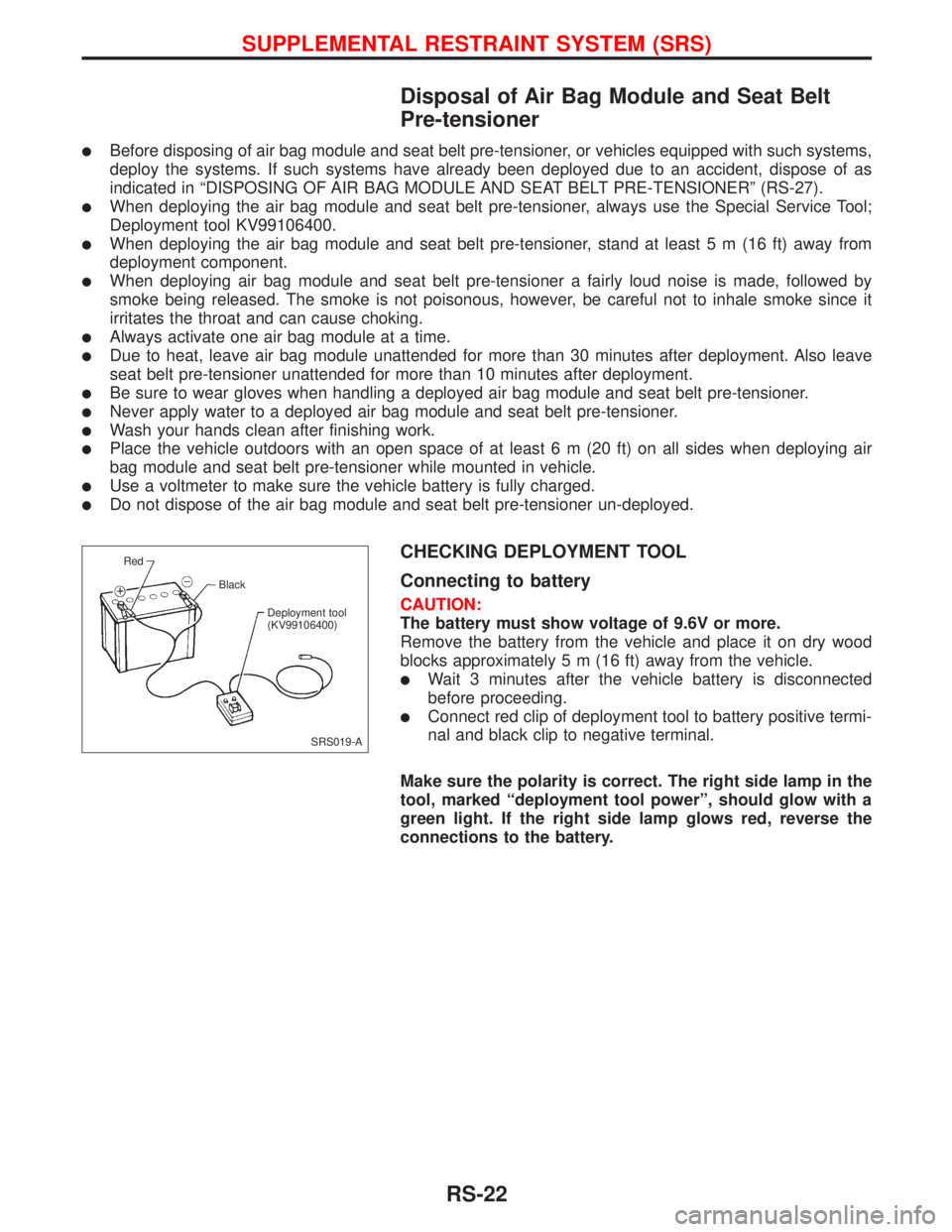
CHECKING DEPLOYMENT TOOL
Connecting to battery
CAUTION:
The battery must show voltage of 9.6V or more.
Remove the battery from the vehicle and place it on dry wood
blocks approximately 5 m (16 ft) away from the vehicle.
lWait 3 minutes after the vehicle battery is disconnected
before proceeding.
lConnect red clip of deployment tool to battery positive termi-
nal and black clip to negative terminal.
Make sure the polarity is correct. The right side lamp in the
tool, marked ªdeployment tool powerº, should glow with a
green light. If the right side lamp glows red, reverse the
connections to the battery.
SRS019-A Red
Black
Deployment tool
(KV99106400)
SUPPLEMENTAL RESTRAINT SYSTEM (SRS)
RS-22
Page 2212 of 2267
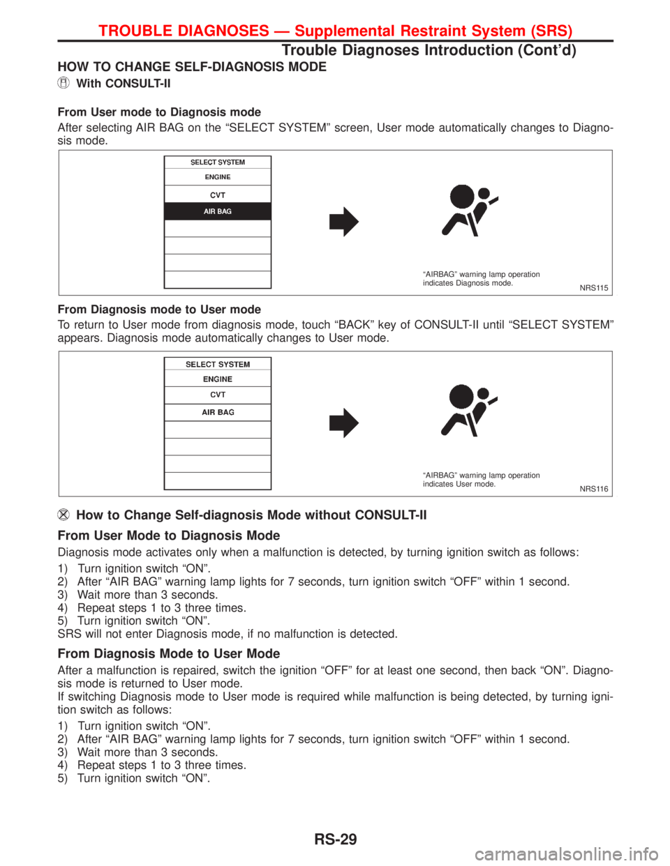
HOW TO CHANGE SELF-DIAGNOSIS MODE
With CONSULT-II
From User mode to Diagnosis mode
After selecting AIR BAG on the ªSELECT SYSTEMº screen, User mode automatically changes to Diagno-
sis mode.
From Diagnosis mode to User mode
To return to User mode from diagnosis mode, touch ªBACKº key of CONSULT-II until ªSELECT SYSTEMº
appears. Diagnosis mode automatically changes to User mode.
How to Change Self-diagnosis Mode without CONSULT-II
From User Mode to Diagnosis Mode
Diagnosis mode activates only when a malfunction is detected, by turning ignition switch as follows:
1) Turn ignition switch ªONº.
2) After ªAIR BAGº warning lamp lights for 7 seconds, turn ignition switch ªOFFº within 1 second.
3) Wait more than 3 seconds.
4) Repeat steps 1 to 3 three times.
5) Turn ignition switch ªONº.
SRS will not enter Diagnosis mode, if no malfunction is detected.
From Diagnosis Mode to User Mode
After a malfunction is repaired, switch the ignition ªOFFº for at least one second, then back ªONº. Diagno-
sis mode is returned to User mode.
If switching Diagnosis mode to User mode is required while malfunction is being detected, by turning igni-
tion switch as follows:
1) Turn ignition switch ªONº.
2) After ªAIR BAGº warning lamp lights for 7 seconds, turn ignition switch ªOFFº within 1 second.
3) Wait more than 3 seconds.
4) Repeat steps 1 to 3 three times.
5) Turn ignition switch ªONº.
NRS115 ªAIRBAGº warning lamp operation
indicates Diagnosis mode.
NRS116 ªAIRBAGº warning lamp operation
indicates User mode.
TROUBLE DIAGNOSES Ð Supplemental Restraint System (SRS)
Trouble Diagnoses Introduction (Cont'd)
RS-29
Page 2231 of 2267
Trouble Diagnoses without CONSULT-II
DIAGNOSTIC PROCEDURE 6
Inspecting SRS malfunction parts by using ªAIR BAGº
warning lamp Ð Diagnosis mode
NOTE:
SRS will not enter Diagnosis mode if no malfunction is
detected in User mode.
1. Turn ignition switch ªONº.
2. After ªAIR BAGº warning lamp lights for 7 seconds, turn igni-
tion switch ªOFFº within 1 second.
3. Wait more than 3 seconds.
4. Repeat steps 1 to 3 three times.
5. Turn ignition switch ªONº.
SRS is now in Diagnosis mode.
6. ªAIR BAGº warning lamp operates in Diagnosis mode as fol-
lows:
NOTE:
If SRS does not enter Diagnosis mode even though malfunction
is detected in User mode, check the battery voltage.
If the battery voltage is less than 9V, charge the battery. Then go
to DIAGNOSTIC PROCEDURE 7, page RS-53.
If the battery voltage is OK, replace the diagnosis sensor unit.
SRS800
TROUBLE DIAGNOSES Ð Supplemental Restraint System (SRS)
RS-48
Page 2237 of 2267
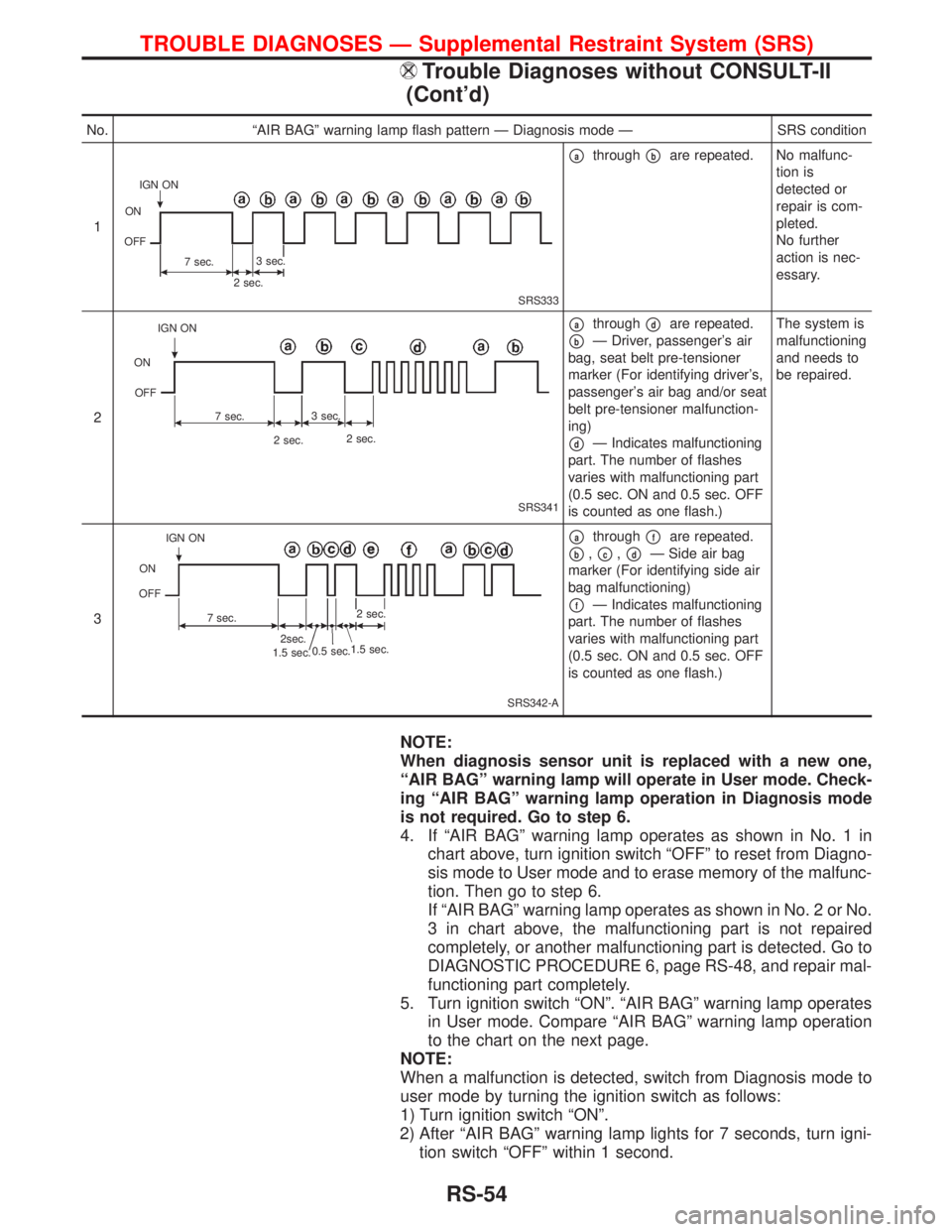
NOTE:
When diagnosis sensor unit is replaced with a new one,
ªAIR BAGº warning lamp will operate in User mode. Check-
ing ªAIR BAGº warning lamp operation in Diagnosis mode
is not required. Go to step 6.
4. If ªAIR BAGº warning lamp operates as shown in No. 1 in
chart above, turn ignition switch ªOFFº to reset from Diagno-
sis mode to User mode and to erase memory of the malfunc-
tion. Then go to step 6.
If ªAIR BAGº warning lamp operates as shown in No. 2 or No.
3 in chart above, the malfunctioning part is not repaired
completely, or another malfunctioning part is detected. Go to
DIAGNOSTIC PROCEDURE 6, page RS-48, and repair mal-
functioning part completely.
5. Turn ignition switch ªONº. ªAIR BAGº warning lamp operates
in User mode. Compare ªAIR BAGº warning lamp operation
to the chart on the next page.
NOTE:
When a malfunction is detected, switch from Diagnosis mode to
user mode by turning the ignition switch as follows:
1) Turn ignition switch ªONº.
2) After ªAIR BAGº warning lamp lights for 7 seconds, turn igni-
tion switch ªOFFº within 1 second.
No. ªAIR BAGº warning lamp flash pattern Ð Diagnosis mode Ð SRS condition
1
SRS333
pathroughpbare repeated. No malfunc-
tion is
detected or
repair is com-
pleted.
No further
action is nec-
essary.
2
SRS341
pathroughpdare repeated.
pbÐ Driver, passenger's air
bag, seat belt pre-tensioner
marker (For identifying driver's,
passenger's air bag and/or seat
belt pre-tensioner malfunction-
ing)
pdÐ Indicates malfunctioning
part. The number of flashes
varies with malfunctioning part
(0.5 sec. ON and 0.5 sec. OFF
is counted as one flash.)The system is
malfunctioning
and needs to
be repaired.
3
SRS342-A
pathroughpfare repeated.
pb,pc,pdÐ Side air bag
marker (For identifying side air
bag malfunctioning)
pfÐ Indicates malfunctioning
part. The number of flashes
varies with malfunctioning part
(0.5 sec. ON and 0.5 sec. OFF
is counted as one flash.)
IGN ON
ON
OFF
7 sec.3 sec.
2 sec.
IGN ON
ON
OFF
7 sec.3 sec.
2 sec.2 sec.
0.5 sec.
1.5 sec. IGN ON
ON
OFF
7 sec.
2sec.
1.5 sec.2 sec.
TROUBLE DIAGNOSES Ð Supplemental Restraint System (SRS)
Trouble Diagnoses without CONSULT-II
(Cont'd)
RS-54