1999 NISSAN PRIMERA light
[x] Cancel search: lightPage 1827 of 2267
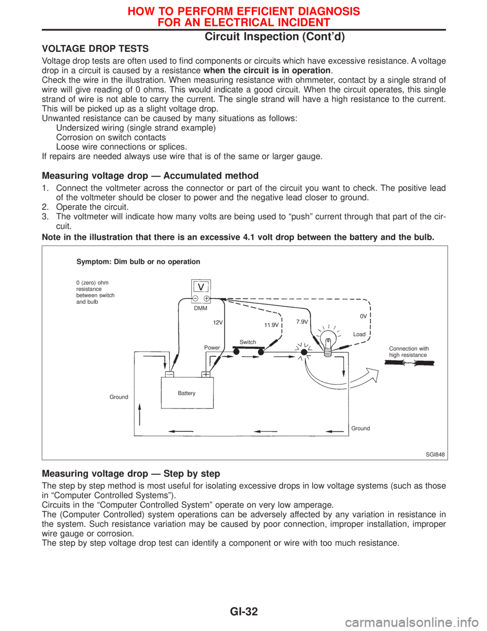
VOLTAGE DROP TESTS
Voltage drop tests are often used to find components or circuits which have excessive resistance. A voltage
drop in a circuit is caused by a resistancewhen the circuit is in operation.
Check the wire in the illustration. When measuring resistance with ohmmeter, contact by a single strand of
wire will give reading of 0 ohms. This would indicate a good circuit. When the circuit operates, this single
strand of wire is not able to carry the current. The single strand will have a high resistance to the current.
This will be picked up as a slight voltage drop.
Unwanted resistance can be caused by many situations as follows:
Undersized wiring (single strand example)
Corrosion on switch contacts
Loose wire connections or splices.
If repairs are needed always use wire that is of the same or larger gauge.
Measuring voltage drop Ð Accumulated method
1. Connect the voltmeter across the connector or part of the circuit you want to check. The positive lead
of the voltmeter should be closer to power and the negative lead closer to ground.
2. Operate the circuit.
3. The voltmeter will indicate how many volts are being used to ªpushº current through that part of the cir-
cuit.
Note in the illustration that there is an excessive 4.1 volt drop between the battery and the bulb.
Measuring voltage drop Ð Step by step
The step by step method is most useful for isolating excessive drops in low voltage systems (such as those
in ªComputer Controlled Systemsº).
Circuits in the ªComputer Controlled Systemº operate on very low amperage.
The (Computer Controlled) system operations can be adversely affected by any variation in resistance in
the system. Such resistance variation may be caused by poor connection, improper installation, improper
wire gauge or corrosion.
The step by step voltage drop test can identify a component or wire with too much resistance.
SGI848
Symptom: Dim bulb or no operation
0 (zero) ohm
resistance
between switch
and bulb
GroundBatteryDMM
PowerSwitchLoad
Connection with
high resistance
Ground
HOW TO PERFORM EFFICIENT DIAGNOSIS
FOR AN ELECTRICAL INCIDENT
Circuit Inspection (Cont'd)
GI-32
Page 1829 of 2267
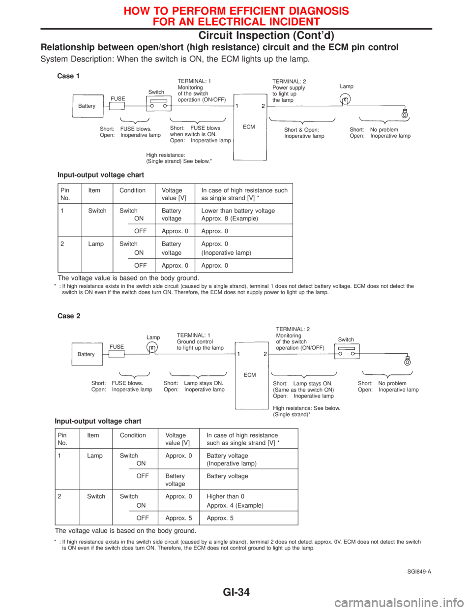
Relationship between open/short (high resistance) circuit and the ECM pin control
System Description: When the switch is ON, the ECM lights up the lamp.
SGI849-A
Case 1
BatteryFUSESwitchTERMINAL: 1
Monitoring
of the switch
operation (ON/OFF)TERMINAL: 2
Power supply
to light up
the lampLamp
Short: FUSE blows.
Open: Inoperative lampShort: FUSE blows
when switch is ON.
Open: Inoperative lamp
High resistance:
(Single strand) See below.*ECM
Short & Open:
Inoperative lampShort: No problem
Open: Inoperative lamp
Case 2
BatteryFUSELampTERMINAL: 1
Ground control
to light up the lampTERMINAL: 2
Monitoring
of the switch
operation (ON/OFF)Switch
Short: FUSE blows.
Open: Inoperative lampShort: Lamp stays ON.
Open: Inoperative lampShort: Lamp stays ON.
(Same as the switch ON)
Open: Inoperative lamp
High resistance: See below.
(Single strand)*Short: No problem
Open: Inoperative lamp ECM
Pin
No.Item Condition Voltage
value [V]In case of high resistance such
as single strand [V] *
1 Switch Switch Battery Lower than battery voltage
ON voltage Approx. 8 (Example)
OFF Approx. 0 Approx. 0
2 Lamp Switch Battery Approx. 0
ON voltage (Inoperative lamp)
OFF Approx. 0 Approx. 0
The voltage value is based on the body ground.
Input-output voltage chart
Pin
No.Item Condition Voltage
value [V]In case of high resistance
such as single strand [V] *
1 Lamp Switch Approx. 0 Battery voltage
ON (Inoperative lamp)
OFF Battery
voltageBattery voltage
2 Switch Switch Approx. 0 Higher than 0
ON Approx. 4 (Example)
OFF Approx. 5 Approx. 5
The voltage value is based on the body ground.
Input-output voltage chart
* : If high resistance exists in the switch side circuit (caused by a single strand), terminal 1 does not detect battery voltage. ECM does not detect the
switch is ON even if the switch does turn ON. Therefore, the ECM does not supply power to light up the lamp.
* : If high resistance exists in the switch side circuit (caused by a single strand), terminal 2 does not detect approx. 0V. ECM does not detect the switch
is ON even if the switch does turn ON. Therefore, the ECM does not control ground to light up the lamp.
HOW TO PERFORM EFFICIENT DIAGNOSIS
FOR AN ELECTRICAL INCIDENT
Circuit Inspection (Cont'd)
GI-34
Page 1847 of 2267
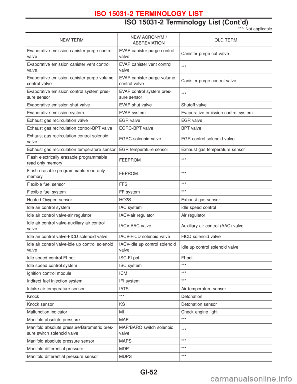
***: Not applicable
NEW TERMNEW ACRONYM /
ABBREVIATIONOLD TERM
Evaporative emission canister purge control
valveEVAP canister purge control
valveCanister purge cut valve
Evaporative emission canister vent control
valveEVAP canister vent control
valve***
Evaporative emission canister purge volume
control valveEVAP canister purge volume
control valveCanister purge control valve
Evaporative emission control system pres-
sure sensorEVAP control system pres-
sure sensor***
Evaporative emission shut valve EVAP shut valve Shutoff valve
Evaporative emission system EVAP system Evaporative emission control system
Exhaust gas recirculation valve EGR valve EGR valve
Exhaust gas recirculation control-BPT valve EGRC-BPT valve BPT valve
Exhaust gas recirculation control-solenoid
valveEGRC-solenoid valve EGR control solenoid valve
Exhaust gas recirculation temperature sensor EGR temperature sensor Exhaust gas temperature sensor
Flash electrically erasable programmable
read only memoryFEEPROM ***
Flash erasable programmable read only
memoryFEPROM ***
Flexible fuel sensor FFS ***
Flexible fuel system FF system ***
Heated Oxygen sensor HO2S Exhaust gas sensor
Idle air control system IAC system Idle speed control
Idle air control valve-air regulator IACV-air regulator Air regulator
Idle air control valve-auxiliary air control
valveIACV-AAC valve Auxiliary air control (AAC) valve
Idle air control valve-FICD solenoid valve IACV-FICD solenoid valve FICD solenoid valve
Idle air control valve-idle up control solenoid
valveIACV-idle up control solenoid
valveIdle up control solenoid valve
Idle speed control-FI pot ISC-FI pot FI pot
Idle speed control system ISC system ***
Ignition control module ICM ***
Indirect fuel injection system IFI system ***
Intake air temperature sensor IATS Air temperature sensor
Knock *** Detonation
Knock sensor KS Detonation sensor
Malfunction indicator MI Check engine light
Manifold absolute pressure MAP ***
Manifold absolute pressure/Barometric pres-
sure switch solenoid valveMAP/BARO switch solenoid
valve***
Manifold absolute pressure sensor MAPS ***
Manifold differential pressure MDP ***
Manifold differential pressure sensor MDPS ***
ISO 15031-2 TERMINOLOGY LIST
ISO 15031-2 Terminology List (Cont'd)
GI-52
Page 1857 of 2267
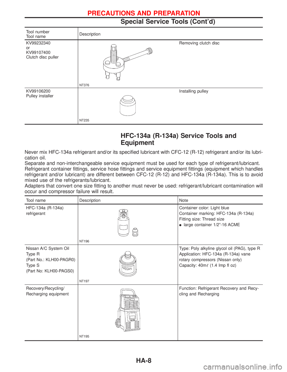
Tool number
Tool nameDescription
KV99232340
or
KV99107400
Clutch disc puller
NT376
Removing clutch disc
KV99106200
Pulley installer
NT235
Installing pulley
HFC-134a (R-134a) Service Tools and
Equipment
Never mix HFC-134a refrigerant and/or its specified lubricant with CFC-12 (R-12) refrigerant and/or its lubri-
cation oil.
Separate and non-interchangeable service equipment must be used for each type of refrigerant/lubricant.
Refrigerant container fittings, service hose fittings and service equipment fittings (equipment which handles
refrigerant and/or lubricant) are different between CFC-12 (R-12) and HFC-134a (R-134a). This is to avoid
mixed use of the refrigerants/lubricant.
Adapters that convert one size fitting to another must never be used: refrigerant/lubricant contamination will
occur and compressor failure will result.
Tool name Description Note
HFC-134a (R-134a)
refrigerant
NT196
Container color: Light blue
Container marking: HFC-134a (R-134a)
Fitting size: Thread size
llarge container 1/2º-16 ACME
Nissan A/C System Oil
Type R
(Part No.: KLH00-PAGR0)
Type S
(Part No: KLH00-PAGS0)
NT197
Type: Poly alkyline glycol oil (PAG), type R
Application: HFC-134a (R-134a) vane
rotary compressors (Nissan only)
Capacity: 40m(1.4 Imp fl oz)
Recovery/Recycling/
Recharging equipment
NT195
Function: Refrigerant Recovery and Recy-
cling and Recharging
PRECAUTIONS AND PREPARATION
Special Service Tools (Cont'd)
HA-8
Page 1858 of 2267
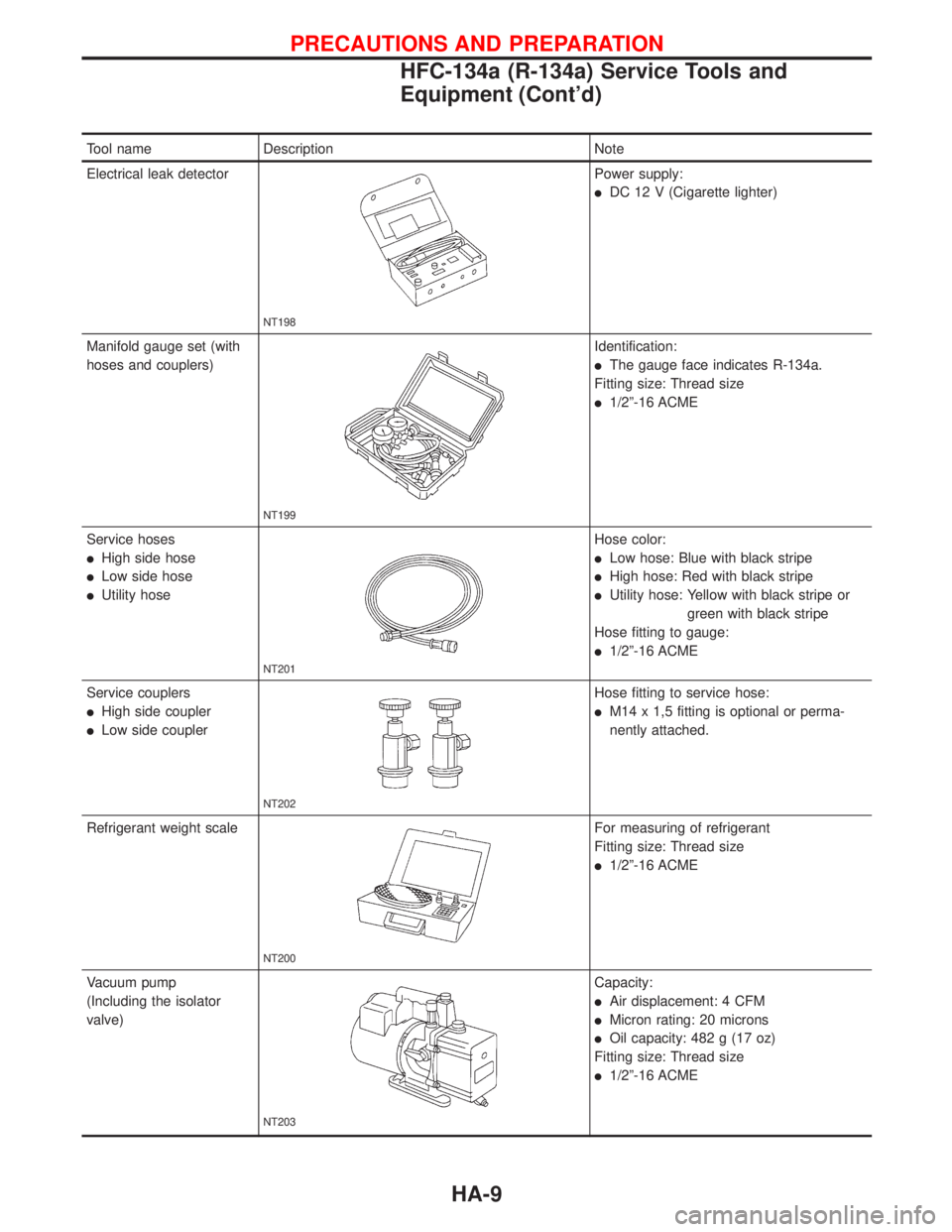
Tool name Description Note
Electrical leak detector
NT198
Power supply:
lDC 12 V (Cigarette lighter)
Manifold gauge set (with
hoses and couplers)
NT199
Identification:
lThe gauge face indicates R-134a.
Fitting size: Thread size
l1/2º-16 ACME
Service hoses
lHigh side hose
lLow side hose
lUtility hose
NT201
Hose color:
lLow hose: Blue with black stripe
lHigh hose: Red with black stripe
lUtility hose: Yellow with black stripe or
green with black stripe
Hose fitting to gauge:
l1/2º-16 ACME
Service couplers
lHigh side coupler
lLow side coupler
NT202
Hose fitting to service hose:
lM14 x 1,5 fitting is optional or perma-
nently attached.
Refrigerant weight scale
NT200
For measuring of refrigerant
Fitting size: Thread size
l1/2º-16 ACME
Vacuum pump
(Including the isolator
valve)
NT203
Capacity:
lAir displacement: 4 CFM
lMicron rating: 20 microns
lOil capacity: 482 g (17 oz)
Fitting size: Thread size
l1/2º-16 ACME
PRECAUTIONS AND PREPARATION
HFC-134a (R-134a) Service Tools and
Equipment (Cont'd)
HA-9
Page 1868 of 2267
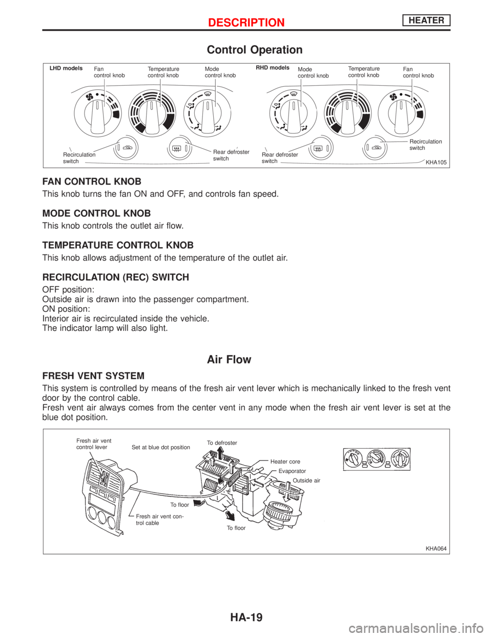
Control Operation
FAN CONTROL KNOB
This knob turns the fan ON and OFF, and controls fan speed.
MODE CONTROL KNOB
This knob controls the outlet air flow.
TEMPERATURE CONTROL KNOB
This knob allows adjustment of the temperature of the outlet air.
RECIRCULATION (REC) SWITCH
OFF position:
Outside air is drawn into the passenger compartment.
ON position:
Interior air is recirculated inside the vehicle.
The indicator lamp will also light.
Air Flow
FRESH VENT SYSTEM
This system is controlled by means of the fresh air vent lever which is mechanically linked to the fresh vent
door by the control cable.
Fresh vent air always comes from the center vent in any mode when the fresh air vent lever is set at the
blue dot position.
KHA105 Fan
control knobTemperature
control knobMode
control knobMode
control knobTemperature
control knobFan
control knob
Rear defroster
switchRecirculation
switch
.Rear defroster
switch Recirculation
switch LHD modelsRHD models
KHA064 Fresh air vent
control lever
Set at blue dot positionTo defroster
Heater core
Evaporator
Outside air
To floor To floor
Fresh air vent con-
trol cable
DESCRIPTIONHEATER
HA-19
Page 1874 of 2267
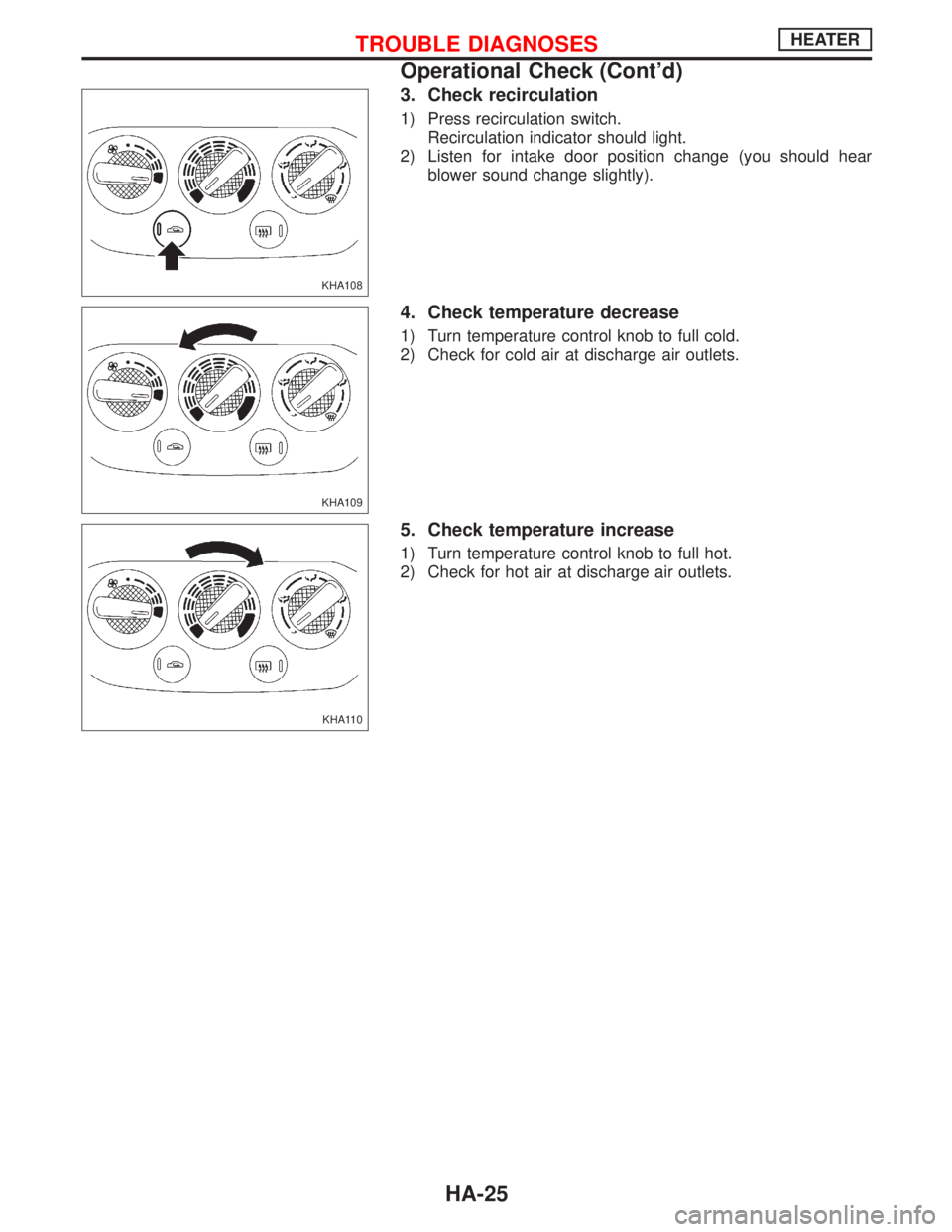
3. Check recirculation
1) Press recirculation switch.
Recirculation indicator should light.
2) Listen for intake door position change (you should hear
blower sound change slightly).
4. Check temperature decrease
1) Turn temperature control knob to full cold.
2) Check for cold air at discharge air outlets.
5. Check temperature increase
1) Turn temperature control knob to full hot.
2) Check for hot air at discharge air outlets.
KHA108
KHA109
KHA110
TROUBLE DIAGNOSESHEATER
Operational Check (Cont'd)
HA-25
Page 1879 of 2267
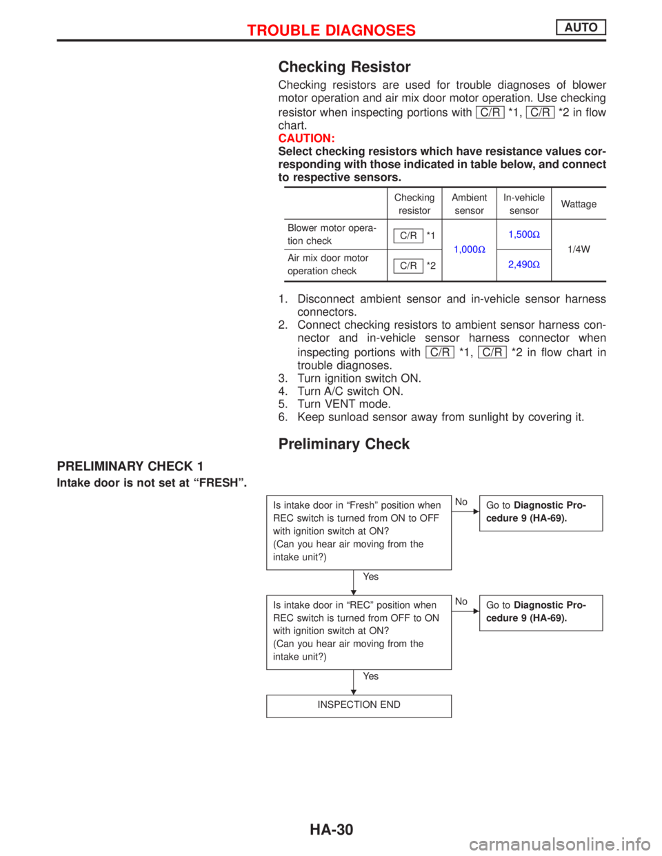
Checking Resistor
Checking resistors are used for trouble diagnoses of blower
motor operation and air mix door motor operation. Use checking
resistor when inspecting portions with C/R
*1, C/R*2 in flow
chart.
CAUTION:
Select checking resistors which have resistance values cor-
responding with those indicated in table below, and connect
to respective sensors.
Checking
resistorAmbient
sensorIn-vehicle
sensorWattage
Blower motor opera-
tion checkC/R
*1
1,000W1,500W
1/4W
Air mix door motor
operation checkC/R
*22,490W
1. Disconnect ambient sensor and in-vehicle sensor harness
connectors.
2. Connect checking resistors to ambient sensor harness con-
nector and in-vehicle sensor harness connector when
inspecting portions with C/R
*1, C/R*2 in flow chart in
trouble diagnoses.
3. Turn ignition switch ON.
4. Turn A/C switch ON.
5. Turn VENT mode.
6. Keep sunload sensor away from sunlight by covering it.
Preliminary Check
PRELIMINARY CHECK 1
Intake door is not set at ªFRESHº.
Is intake door in ªFreshº position when
REC switch is turned from ON to OFF
with ignition switch at ON?
(Can you hear air moving from the
intake unit?)
Ye s
ENo
Go toDiagnostic Pro-
cedure 9 (HA-69).
Is intake door in ªRECº position when
REC switch is turned from OFF to ON
with ignition switch at ON?
(Can you hear air moving from the
intake unit?)
Ye s
ENo
Go toDiagnostic Pro-
cedure 9 (HA-69).
INSPECTION END
H
H
TROUBLE DIAGNOSESAUTO
HA-30