Page 1315 of 2267
Trouble Diagnoses
SYMPTOM CHART
REFERENCE PAGE EL-183 EL-184 EL-184 EL-185
SYMPTOM
POWER SUPPLY AND
GROUND CIRCUIT CHECK
DIAGNOSTIC PROCEDURE 1
(Lighting switch input signal check)
DIAGNOSTIC PROCEDURE 2
(Key switch input signal check)
DIAGNOSTIC PROCEDURE 3
Light warning chime does not acti-
vate.XX X
Ignition key warning chime does
not activate.XXX
All warning chimes do not activate. X X
POWER SUPPLY AND GROUND CIRCUIT CHECK
Power Supply Circuit Check
Terminals Ignition switch position
��OFF ACC ON
�9GroundBattery
voltageBattery
voltageBattery
voltage
�1Ground 0V 0VBattery
voltage
Ground Circuit Check
Terminals Continuity
�16- Ground Yes
Time control
unit connector
YEL430B
Time control unit connector
YEL431B
WARNING CHIME
EL-183
Page 1316 of 2267

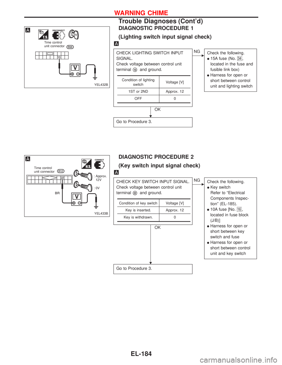
DIAGNOSTIC PROCEDURE 1
(Lighting switch input signal check)
CHECK LIGHTING SWITCH INPUT
SIGNAL.
Check voltage between control unit
terminal
�10and ground.
OK
�NG
Check the following.
�15A fuse (No.34,
located in the fuse and
fusible link box)
�Harness for open or
short between control
unit and lighting switch
Go to Procedure 3.
Condition of lighting
switchVoltage [V]
1ST or 2ND Approx. 12
OFF 0
DIAGNOSTIC PROCEDURE 2
(Key switch input signal check)
CHECK KEY SWITCH INPUT SIGNAL.
Check voltage between control unit
terminal
�22and ground.
OK
�NG
Check the following.
�Key switch
Refer to“Electrical
Components Inspec-
tion”(EL-185).
�10A fuse [No.16,
located in fuse block
(J/B)]
�Harness for open or
short between key
switch and fuse
�Harness for open or
short between control
unit and key switch
Go to Procedure 3.
Condition of key switch Voltage [V]
Key is inserted. Approx. 12
Key is withdrawn. 0
YEL432B
Time control
unit connector
YEL433B
Time control
unit connector
: Approx.
12V
:0V
�
�
WARNING CHIME
Trouble Diagnoses (Cont’d)
EL-184
Page 1332 of 2267
Wiring Diagram—HLC—
YEL319B
B
G
12
LG/Bd13GE104
2
E128
3
B R/B
B
A
5 LG/B4 G2 P/L
E126
P/L
P/L
3
OR/B1
R/B
E37E11
L
EL-HLC-01
E126
E104
E38
XH HD
HD 10A 30A
XH
HD
1 2 OR/B
BE38
M
B
B
12
E1281
36
24
5 3
241
5
BATTERYIGNITION SWITCH
ON or START
FUSE
BLOCK
(J/B)Refer to EL-POWER.: With XENON headlamp or day-
time light system
: Except
HEADLAMP
WASHER TIMERNext page
HEADLAMP
WASHER
MOTORHEADLAMP
WASHER
SWITCH
OFFON
REFER TO THE FOLLOWING
FUSE BLOCK - Junction Box (J/B)
HEADLAMP WASHER
EL-200
Page 1333 of 2267
YEL179C
: With gasoline engine
: With diesel engine
: With XENON headlamp or
daytime light system
: Except
: With daytime light system and
without XENON headlamp
: With daytime light system
and XENON headlamp
: With XENON headlamp and
without daytime light system.BATTERY
Refer to EL-POWER.
OFF1ST2ND
OFF1ST2ND
COMBINATION
SWITCH
(LIGHTING SWITCH)
LOW
HIGH
Preceding
page
DIODE HEADLAMP
RELAY RHHEADLAMP
RELAY RHHEADLAMP
RELAY RH
Preceding
page
To Headlamp RH
(Refer to EL-H/LAMP and
EL-DTRL)PASS
HEADLAMP WASHER
Wiring Diagram—HLC—(Cont’d)
EL-201
Page 1335 of 2267
Wiring Diagram—HORN—
Type-1
YEL180C
BATTERY
Refer to EL-POWER.: With gasoline engine
: With diesel engine
: With steering wheel switch
: Without steering wheel switch
HORN
RELAY
HORN
LOWHORN
HIGH
OFFON HORN
SWITCHHORN
SWITCH
REFER TO THE FOLLOWING
FUSE BLOCK - Junction Box (J/B)
FUSE BLOCK - Junction Box (J/B)
*: This connector is not shown in“HARNESS LAYOUT”of EL section.OFFONFUSE
BLOCK
(J/B)
SPIRAL
CABLE
HORN, CIGARETTE LIGHTER AND CLOCK
EL-203
Page 1336 of 2267
YEL181C
IGNITION SWITCH
ACC or ONBATTERYIGNITION SWITCH
ON or START
FUSE
BLOCK
(J/B)BATTERY
Refer to EL-POWER.
POWER
FUSE
15A: With gasoline engine
: With diesel engine
: With XENON headlamp,
gasoline engine
: Except
CLOCKCOMBINATION
METER
(CLOCK)
CIGARETTE
LIGHTER
SOCKET
POWER
SOCKET
REFER TO THE FOLLOWING
FUSE BLOCK - Junction Box (J/B) ACCESSORY
RELAY IGNITION
SWITCH OFF
ONST
ACC
ACC
HORN, CIGARETTE LIGHTER AND CLOCK
Wiring Diagram—HORN—(Cont’d)
EL-204
Page 1337 of 2267
Type-2
YEL885C
HORN, CIGARETTE LIGHTER AND CLOCK
Wiring Diagram—HORN—(Cont’d)
EL-205
Page 1338 of 2267
YEL886C
HORN, CIGARETTE LIGHTER AND CLOCK
Wiring Diagram—HORN—(Cont’d)
EL-206