Page 1316 of 2890
B4M0628
G: INSTALLATION
1) Install hydraulic unit and bracket.
Tightening torque:
32±7 N⋅m (3.3±0.7 kg-m, 23.9±5.1 ft-lb)
2) Connect brake pipes to their correct hydraulic unit con-
nections.
3) Connect connector to hydraulic unit.
4) Install canister.
5) Install air cleaner case.
6) Install air intake duct.
7) Connect ground cable to battery.
CAUTION:
Cover relay securely with rubber boot.
21. ABS/TCS Control Module
A: REMOVAL
1) Disconnect ground cable from battery.
2) Remove floor mat located under lower right side of front
seat.
B4M0643A
3) Remove screw which secure ABS/TCS control module
from the body.
4) Disconnect connector from ABS/TCS control module.
B: INSPECTION
Check that connector is connected correctly and that con-
nector terminal sliding resistance is correct.
107
4-4SERVICE PROCEDURE
20. Hydraulic Unit for ABS/TCS System - 21. ABS/TCS Control Module
Page 1317 of 2890
B4M0628
G: INSTALLATION
1) Install hydraulic unit and bracket.
Tightening torque:
32±7 N⋅m (3.3±0.7 kg-m, 23.9±5.1 ft-lb)
2) Connect brake pipes to their correct hydraulic unit con-
nections.
3) Connect connector to hydraulic unit.
4) Install canister.
5) Install air cleaner case.
6) Install air intake duct.
7) Connect ground cable to battery.
CAUTION:
Cover relay securely with rubber boot.
21. ABS/TCS Control Module
A: REMOVAL
1) Disconnect ground cable from battery.
2) Remove floor mat located under lower right side of front
seat.
B4M0643A
3) Remove screw which secure ABS/TCS control module
from the body.
4) Disconnect connector from ABS/TCS control module.
B: INSPECTION
Check that connector is connected correctly and that con-
nector terminal sliding resistance is correct.
107
4-4SERVICE PROCEDURE
20. Hydraulic Unit for ABS/TCS System - 21. ABS/TCS Control Module
Page 1318 of 2890
C: INSTALLATION
1) Connect connector to ABS/TCS control module.
2) Install ABS/TCS control module on the body.
CAUTION:
�When installing seat rail, be careful no to have the
harness caught in the rail.
�Cover the connector completely with rubber boot.
108
4-4SERVICE PROCEDURE
21. ABS/TCS Control Module
Page 1335 of 2890
 Fluid leakage from the hydraulic mechanismRepair or replace (cup, piston seal, piston boot, master cylin")
1. Entire Brake System
Trouble and possible cause Corrective action
1. Insufficient braking
(1) Fluid leakage from the hydraulic mechanismRepair or replace (cup, piston seal, piston boot, master cylinder
piston kit, pipe or hose).
(2) Entry of air into the hydraulic mechanism Bleed the air.
(3) Excessively wide shoe clearance Adjust the clearance.
(4) Wear, deteriorated surface material, adhering water or fluid
on the liningReplace, grind or clean.
(5) Improper operation of master cylinder, disc caliper, brake
booster or check valveCorrect or replace.
2. Unstable or uneven braking
(1) Fluid on the lining, drum or rotor Eliminate cause of fluid leakage, clean, or replace.
(2) Drum or rotor eccentricity Correct or replace the drum or rotor.
(3) Worn brake drum, or damage to the drum caused by sand Correct by grinding, or replace.
(4) Improper lining contact, deteriorated surface material,
improper inferior material, or wearCorrect by grinding, or replace.
(5) Deformed back plate Correct or replace.
(6) Improper tire inflation Inflate to correct pressure.
(7) Disordered wheel alignment Adjust alignment.
(8) Loosened back plate or the support installing bolts Retighten.
(9) Loosened wheel bearing Retighten to normal tightening torque or replace.
(10) Trouble in the hydraulic system Replace the cylinder, brake pipe or hose.
(11) Uneven effect of the parking brake Check, adjust, or replace the rear brake and cable system.
3. Excessive pedal stroke
(1) Entry of air into the hydraulic mechanism Bleed the air.
(2) Excessive play in the master cylinder push rod Adjust.
(3) Fluid leakage from the hydraulic mechanismRepair or replace (cup, piston seal, piston boot, master cylinder
piston kit, pipe or hose).
(4) Improperly adjusted shoe clearance Adjust.
(5) Improper lining contact or worn lining Correct or replace.
124
4-4DIAGNOSTICS
1. Entire Brake System
Page 1350 of 2890
G4M0330
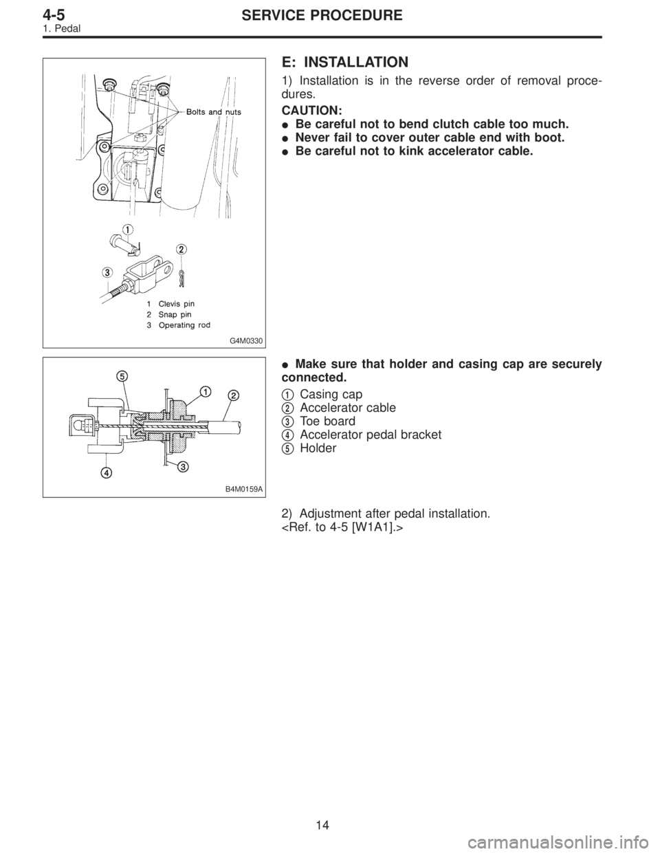
E: INSTALLATION
1) Installation is in the reverse order of removal proce-
dures.
CAUTION:
�Be careful not to bend clutch cable too much.
�Never fail to cover outer cable end with boot.
�Be careful not to kink accelerator cable.
B4M0159A
�Make sure that holder and casing cap are securely
connected.
�
1Casing cap
�
2Accelerator cable
�
3Toe board
�
4Accelerator pedal bracket
�
5Holder
2) Adjustment after pedal installation.
14
4-5SERVICE PROCEDURE
1. Pedal
Page 1565 of 2890
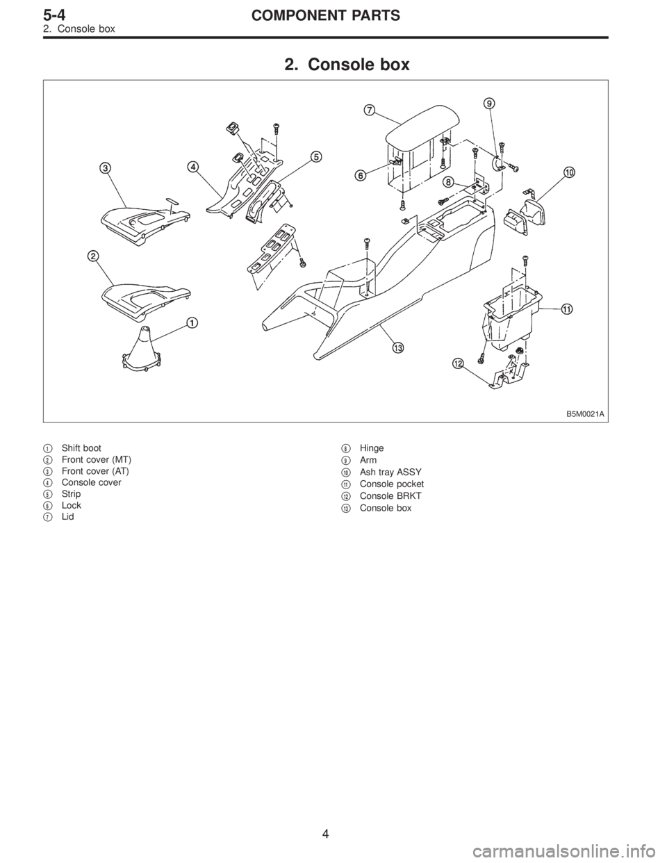
2. Console box
B5M0021A
�1Shift boot
�
2Front cover (MT)
�
3Front cover (AT)
�
4Console cover
�
5Strip
�
6Lock
�
7Lid�
8Hinge
�
9Arm
�
10Ash tray ASSY
�
11Console pocket
�
12Console BRKT
�
13Console box
4
5-4COMPONENT PARTS
2. Console box
Page 1636 of 2890

NGK: BKR6E-11
NIPPONDENSO: K20PR-U1")
3. Spark Plug
A: REMOVAL AND INSTALLATION
CAUTION:
All spark plugs installed on an engine, must be of the
same heat range.
Spark plug:
CHAMPION: RC10YC4
(Alternate)
NGK: BKR6E-11
NIPPONDENSO: K20PR-U11
1) Remove spark plug cords by pulling boot, not cord itself.
2) Remove spark plugs.
3) When installing spark plugs on cylinder head, use spark
plug wrench.
Tightening torque (Spark plug):
20.6±2.9 N⋅m (2.10±0.30 kg-m, 15.19±2.14 ft-lb)
CAUTION:
The above torque should be only applied to new spark
plugs without oil on their threads.
In case their threads are lubricated, the torque should
be reduced by approximately 1/3 of the specified
torque in order to avoid their over-stressing.
4) Connect spark plug cords.
G6M0086
B: INSPECTION
Check electrodes and inner and outer porcelain of plugs,
noting the type of deposits and the degree of electrode
erosion.
G6M0087
1) Normal
Brown to grayish-tan deposits and slight electrode wear
indicate correct spark plug heat range.
22
6-1SERVICE PROCEDURE
3. Spark Plug
Page 1638 of 2890
G6M0095
1. #1 SPARK PLUG
1) Disconnect battery ground cable.
B6M0552A
2) Remove #1 spark plug cord by pulling boot, not cord
itself.
B6M0553
3) Remove spark plug with the spark plug socket.
4) Installation is in the reverse order of removal.
Tightening torque (Spark plug):
20.6±2.9 N⋅m (2.10±0.30 kg-m, 15.19±2.14 ft-lb)
G6M0095
2. #2 SPARK PLUG
1) Disconnect battery ground cable.
24
6-1SERVICE PROCEDURE
3. Spark Plug
 Install hydraulic unit and bracket.
Tightening torque:
32±7 N⋅m (3.3±0.7 kg-m, 23.9±5.1 ft-lb)
2) Connect brake pipes to their correct hydraulic unit con-
nections. <Re")
 Install hydraulic unit and bracket.
Tightening torque:
32±7 N⋅m (3.3±0.7 kg-m, 23.9±5.1 ft-lb)
2) Connect brake pipes to their correct hydraulic unit con-
nections. <Re")
 Disconnect battery ground cable.
B6M0552A
2) Remove #1 spark plug cord by pulling boot, not cord
itself.
B6M0553
3) Remove spark plug with the spark plug socket.
4) Install")