Page 1214 of 2890
1. Front Disc Brake
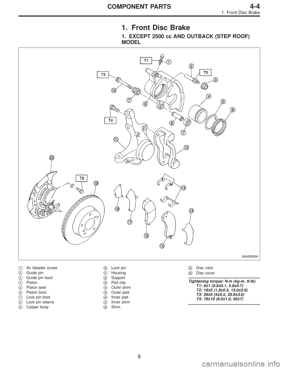
1. EXCEPT 2500 cc AND OUTBACK (STEP ROOF)
MODEL
B4M0065A
�1Air bleeder screw
�
2Guide pin
�
3Guide pin boot
�
4Piston
�
5Piston seal
�
6Piston boot
�
7Lock pin boot
�
8Lock pin sleeve
�
9Caliper body�
10Lock pin
�
11Housing
�
12Support
�
13Pad clip
�
14Outer shim
�
15Outer pad
�
16Inner pad
�
17Inner shim
�
18Shim�
19Disc rotor
�
20Disc cover
Tightening torque: N⋅m (kg-m, ft-lb)
T1: 8±1 (0.8±0.1, 5.8±0.7)
T2: 18±5 (1.8±0.5, 13.0±3.6)
T3: 39±5 (4±0.5, 28.9±3.6)
T4: 78±10 (8.0±1.0, 58±7)
9
4-4COMPONENT PARTS
1. Front Disc Brake
Page 1215 of 2890
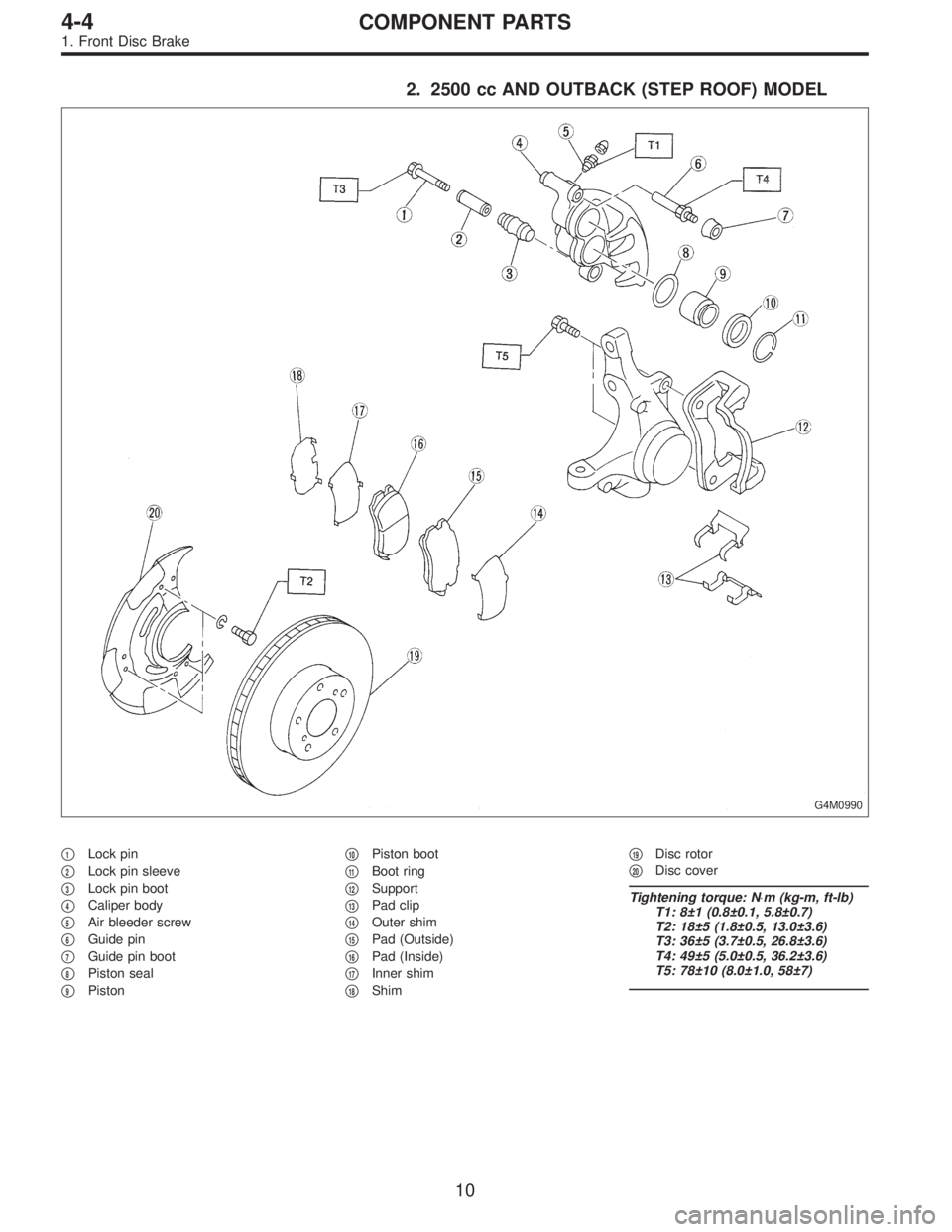
2. 2500 cc AND OUTBACK (STEP ROOF) MODEL
G4M0990
�1Lock pin
�
2Lock pin sleeve
�
3Lock pin boot
�
4Caliper body
�
5Air bleeder screw
�
6Guide pin
�
7Guide pin boot
�
8Piston seal
�
9Piston�
10Piston boot
�
11Boot ring
�
12Support
�
13Pad clip
�
14Outer shim
�
15Pad (Outside)
�
16Pad (Inside)
�
17Inner shim
�
18Shim�
19Disc rotor
�
20Disc cover
Tightening torque: N⋅m (kg-m, ft-lb)
T1: 8±1 (0.8±0.1, 5.8±0.7)
T2: 18±5 (1.8±0.5, 13.0±3.6)
T3: 36±5 (3.7±0.5, 26.8±3.6)
T4: 49±5 (5.0±0.5, 36.2±3.6)
T5: 78±10 (8.0±1.0, 58±7)
10
4-4COMPONENT PARTS
1. Front Disc Brake
Page 1216 of 2890
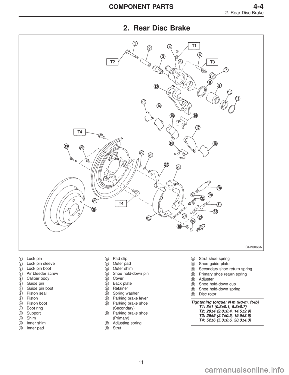
2. Rear Disc Brake
B4M0066A
�1Lock pin
�
2Lock pin sleeve
�
3Lock pin boot
�
4Air bleeder screw
�
5Caliper body
�
6Guide pin
�
7Guide pin boot
�
8Piston seal
�
9Piston
�
10Piston boot
�
11Boot ring
�
12Support
�
13Shim
�
14Inner shim
�
15Inner pad�
16Pad clip
�
17Outer pad
�
18Outer shim
�
19Shoe hold-down pin
�
20Cover
�
21Back plate
�
22Retainer
�
23Spring washer
�
24Parking brake lever
�
25Parking brake shoe
(Secondary)
�
26Parking brake shoe
(Primary)
�
27Adjusting spring
�
28Strut�
29Strut shoe spring
�
30Shoe guide plate
�
31Secondary shoe return spring
�
32Primary shoe return spring
�
33Adjuster
�
34Shoe hold-down cup
�
35Shoe hold-down spring
�
36Disc rotor
Tightening torque: N⋅m (kg-m, ft-lb)
T1: 8±1 (0.8±0.1, 5.8±0.7)
T2: 20±4 (2.0±0.4, 14.5±2.9)
T3: 26±5 (2.7±0.5, 19.5±3.6)
T4: 52±6 (5.3±0.6, 38.3±4.3)
11
4-4COMPONENT PARTS
2. Rear Disc Brake
Page 1217 of 2890
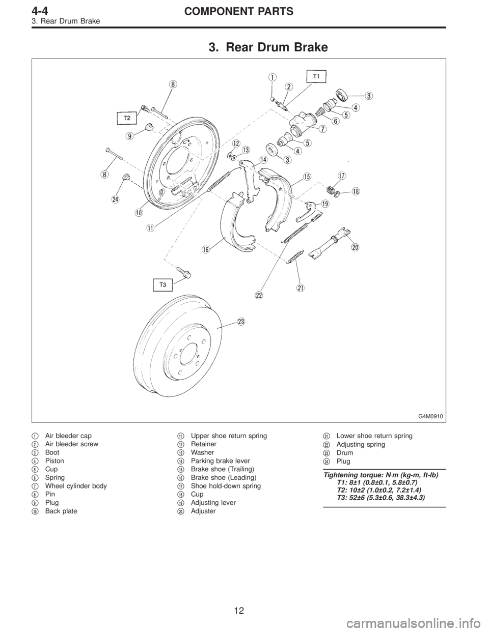
3. Rear Drum Brake
G4M0910
�1Air bleeder cap
�
2Air bleeder screw
�
3Boot
�
4Piston
�
5Cup
�
6Spring
�
7Wheel cylinder body
�
8Pin
�
9Plug
�
10Back plate�
11Upper shoe return spring
�
12Retainer
�
13Washer
�
14Parking brake lever
�
15Brake shoe (Trailing)
�
16Brake shoe (Leading)
�
17Shoe hold-down spring
�
18Cup
�
19Adjusting lever
�
20Adjuster�
21Lower shoe return spring
�
22Adjusting spring
�
23Drum
�
24Plug
Tightening torque: N⋅m (kg-m, ft-lb)
T1: 8±1 (0.8±0.1, 5.8±0.7)
T2: 10±2 (1.0±0.2, 7.2±1.4)
T3: 52±6 (5.3±0.6, 38.3±4.3)
12
4-4COMPONENT PARTS
3. Rear Drum Brake
Page 1229 of 2890
1. Front Disc Brake
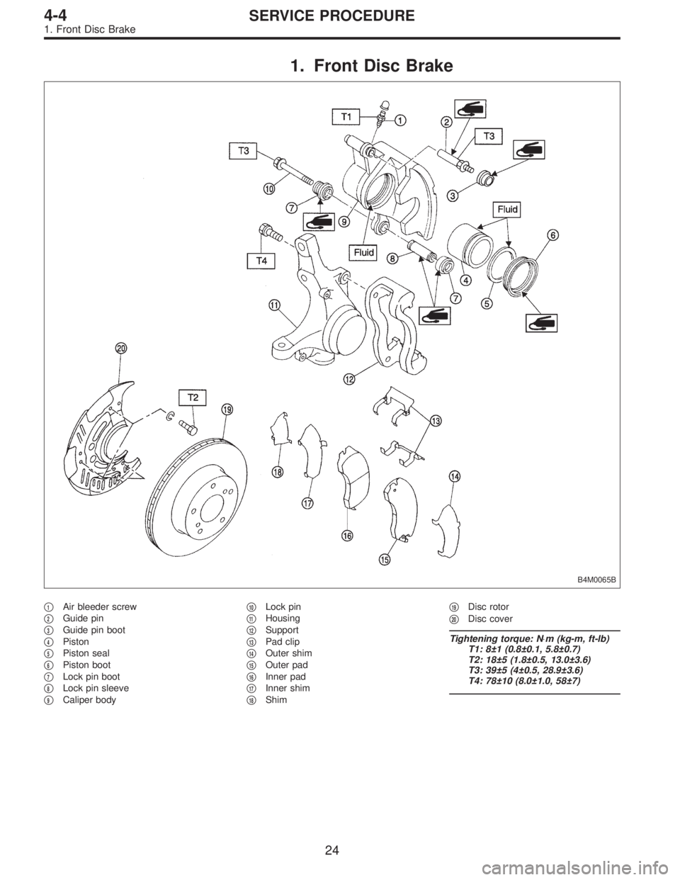
B4M0065B
�1Air bleeder screw
�
2Guide pin
�
3Guide pin boot
�
4Piston
�
5Piston seal
�
6Piston boot
�
7Lock pin boot
�
8Lock pin sleeve
�
9Caliper body�
10Lock pin
�
11Housing
�
12Support
�
13Pad clip
�
14Outer shim
�
15Outer pad
�
16Inner pad
�
17Inner shim
�
18Shim�
19Disc rotor
�
20Disc cover
Tightening torque: N⋅m (kg-m, ft-lb)
T1: 8±1 (0.8±0.1, 5.8±0.7)
T2: 18±5 (1.8±0.5, 13.0±3.6)
T3: 39±5 (4±0.5, 28.9±3.6)
T4: 78±10 (8.0±1.0, 58±7)
24
4-4SERVICE PROCEDURE
1. Front Disc Brake
Page 1232 of 2890
 Remove disc rotor from hub.
NOTE:
If disc rotor seizes up within hub, drive disc rotor out by
installing an 8-mm bolt in holes B on the rotor.
6) Clean mud and foreign particles from calipe")
G4M0365
5) Remove disc rotor from hub.
NOTE:
If disc rotor seizes up within hub, drive disc rotor out by
installing an 8-mm bolt in holes B on the rotor.
6) Clean mud and foreign particles from caliper body
assembly and support.
C: DISASSEMBLY
1. EXCEPT 2500 cc AND OUTBACK (STEP ROOF)
MODEL
1) Clean mud and foreign particles from caliper body
assembly and support.
CAUTION:
Be careful not to allow foreign particles to enter inlet
(at brake hose connector).
G4M0371
2) Gradually supply compressed air via caliper body brake
hose to force piston out.
CAUTION:
�Place a wooden block as shown in Figure to prevent
damage to piston.
�Do not apply excessively high-pressure.
3) Remove piston boot.
4) Remove piston seal from caliper body cylinder.
5) Remove lock pin sleeve and boot from caliper body.
6) Remove guide pin boot.
2. 2500 cc AND OUTBACK (STEP ROOF) MODEL
1) Clean mud and foreign particles from caliper body
assembly and support.
CAUTION:
Be careful not to allow foreign particles to enter inlet
(at brake hose connector).
B4M0769A
2) Using a standard screwdriver, remove boot ring from
piston.
3) Remove boot from piston end.
27
4-4SERVICE PROCEDURE
1. Front Disc Brake
Page 1233 of 2890
 Gradually supply compressed air via caliper body brake
hose to force piston out.
CAUTION:
Place a wooden block as shown in Figure to prevent
damage to piston.
5) Remove piston seal from ca")
B4M0770A
4) Gradually supply compressed air via caliper body brake
hose to force piston out.
CAUTION:
Place a wooden block as shown in Figure to prevent
damage to piston.
5) Remove piston seal from caliper body cylinder.
6) Remove lock pin sleeve and boot from caliper body.
7) Remove guide pin boot.
D: INSPECTION
1) Repair or replace faulty parts.
2) Check caliper body and piston for uneven wear, dam-
age or rust.
3) Check rubber parts for damage or deterioration.
E: ASSEMBLY
1. EXCEPT 2500 cc AND OUTBACK (STEP ROOF)
MODEL
1) Clean caliper body interior using brake fluid.
2) Apply a coat of brake fluid to piston seal and fit piston
seal in groove on caliper body.
3) Apply a coat of brake fluid to the entire inner surface of
cylinder and outer surface of piston.
4) Apply a coat of specified grease to boot and fit in groove
on ends of cylinder and install piston boot onto cylinder.
Grease:
NIGLUBE RX-2 (Part No. 003606000)
G4M0372
5) Insert piston into cylinder.
CAUTION:
Do not force piston into cylinder.
28
4-4SERVICE PROCEDURE
1. Front Disc Brake
Page 1234 of 2890
B4M0072A
6) Position boot in grooves on cylinder and piston.
B4M0073A
7) Apply a coat of specified grease to guide pin, outer
surface, sleeve outer surface, cylinder inner surface, and
boot grooves.
Grease:
NIGLUBE RX-2 (Part No. 003606000)
8) Install guide pin boots on caliper body.
9) Install lock pin boots on caliper body and insert lock pin
sleeve into place.
B4M0074A
2. 2500 cc AND OUTBACK (STEP ROOF) MODEL
1) Clean caliper body interior using brake fluid.
2) Apply a coat of brake fluid to piston seal and fit piston
seal in groove on caliper body.
3) Apply a coat of brake fluid to the entire inner surface of
cylinder and outer surface of piston.
B4M0771A
4) Insert piston into cylinder.
CAUTION:
Do not force piston into cylinder.
29
4-4SERVICE PROCEDURE
1. Front Disc Brake
 Position boot in grooves on cylinder and piston.
B4M0073A
7) Apply a coat of specified grease to guide pin, outer
surface, sleeve outer surface, cylinder inner surface, and
boot grooves.
G")