Page 1235 of 2890
G4M0373
5) Apply a coat of specified grease to boot and fit in groove
on ends of cylinder and piston.
Grease:
NIGLUBE RX-2 (Part No. 003606000)
To facilitate installation, fit boot starting with piston end.
6) Install boot ring. Be careful not scratch boot.
G4M0374
7) Apply a coat of specified grease to guide pin, outer
surface, sleeve outer surface, cylinder inner surface, and
boot grooves.
Grease:
NIGLUBE RX-2 (Part No. 003606000)
8) Install guide pin boots on caliper body.
9) Install lock pin boots on caliper body and insert lock pin
sleeve into place.
G4M0375
30
4-4SERVICE PROCEDURE
1. Front Disc Brake
Page 1237 of 2890
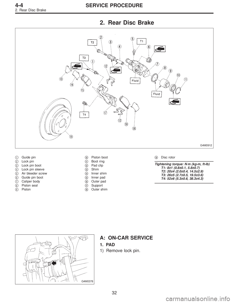
2. Rear Disc Brake
G4M0912
�1Guide pin
�
2Lock pin
�
3Lock pin boot
�
4Lock pin sleeve
�
5Air bleeder screw
�
6Guide pin boot
�
7Caliper body
�
8Piston seal
�
9Piston�
10Piston boot
�
11Boot ring
�
12Pad clip
�
13Shim
�
14Inner shim
�
15Inner pad
�
16Outer pad
�
17Support
�
18Outer shim�
19Disc rotor
Tightening torque: N⋅m (kg-m, ft-lb)
T1: 8±1 (0.8±0.1, 5.8±0.7)
T2: 20±4 (2.0±0.4, 14.5±2.9)
T3: 26±5 (2.7±0.5, 19.5±3.6)
T4: 52±6 (5.3±0.6, 38.3±4.3)
G4M0378
A: ON-CAR SERVICE
1. PAD
1) Remove lock pin.
32
4-4SERVICE PROCEDURE
2. Rear Disc Brake
Page 1240 of 2890
G4M0370
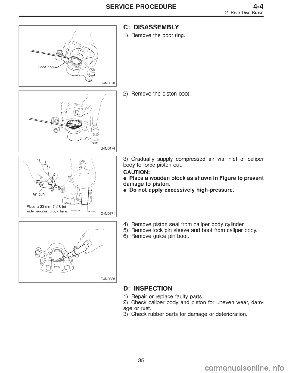
C: DISASSEMBLY
1) Remove the boot ring.
G4M0474
2) Remove the piston boot.
G4M0371
3) Gradually supply compressed air via inlet of caliper
body to force piston out.
CAUTION:
�Place a wooden block as shown in Figure to prevent
damage to piston.
�Do not apply excessively high-pressure.
G4M0388
4) Remove piston seal from caliper body cylinder.
5) Remove lock pin sleeve and boot from caliper body.
6) Remove guide pin boot.
D: INSPECTION
1) Repair or replace faulty parts.
2) Check caliper body and piston for uneven wear, dam-
age or rust.
3) Check rubber parts for damage or deterioration.
35
4-4SERVICE PROCEDURE
2. Rear Disc Brake
Page 1241 of 2890
E: ASSEMBLY
1) Clean caliper body interior using brake fluid.
2) Apply a coat of brake fluid to piston seal and fit piston
seal in groove on caliper body.
3) Apply a coat of brake fluid to the entire inner surface of
cylinder and outer surface of piston.
4) Insert piston into cylinder.
CAUTION:
Do not force piston into cylinder.
5) Apply a coat of specified grease to boot and fit in groove
on ends of cylinder and piston.
Grease:
NIGLUBE RX-2 (Part No. 003606000)
G4M0373
6) Install the piston boot to the caliper body, and attach
boot ring.
G4M0390
7) Apply a coat of specified grease to guide pin, outer
surface, sleeve outer surface, cylinder inner surface, and
boot grooves.
Grease:
NIGLUBE RX-2 (Part No. 003606000)
8) Install guide pin boot on caliper body.
9) Install lock pin boot on caliper body and insert lock pin
sleeve into place.
G4M0375
36
4-4SERVICE PROCEDURE
2. Rear Disc Brake
Page 1243 of 2890
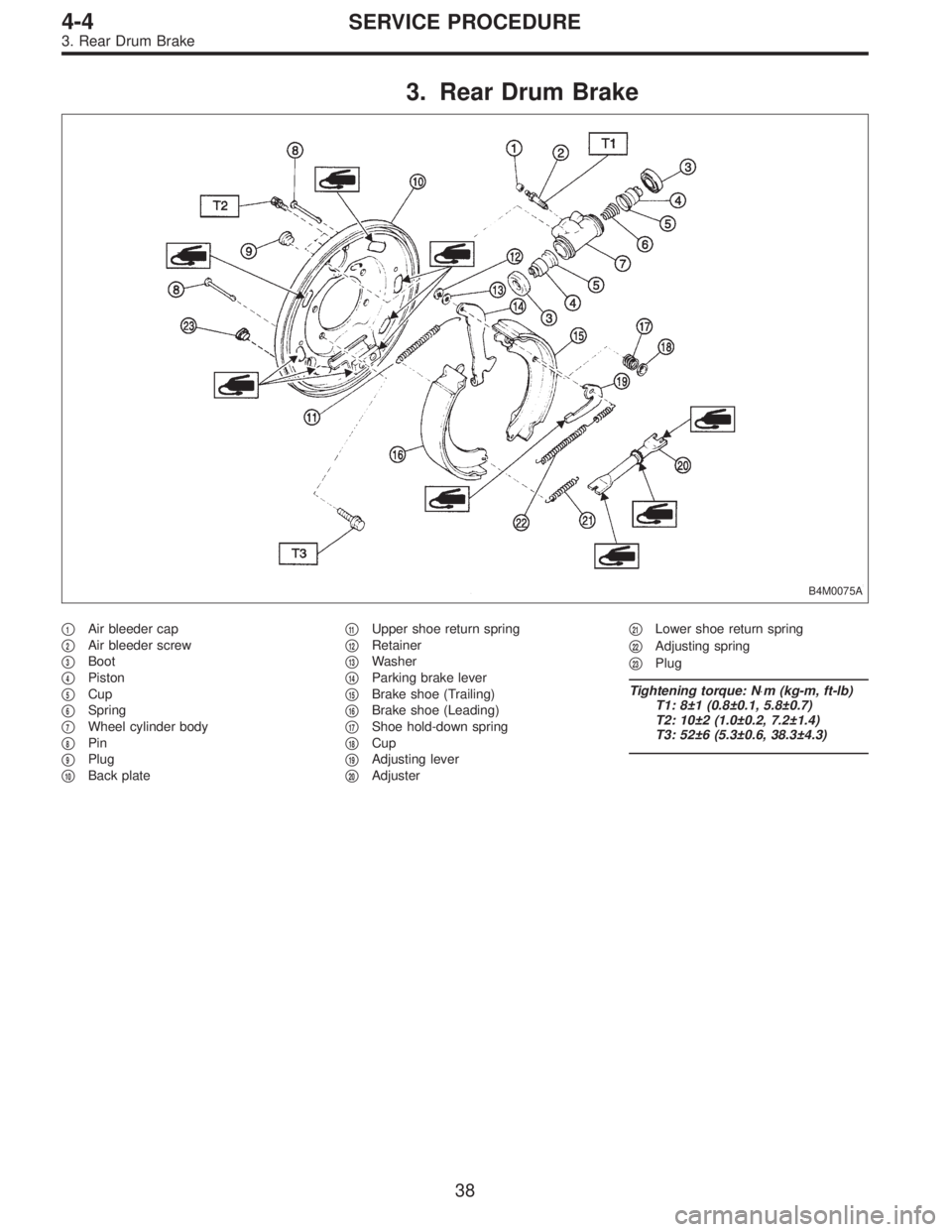
3. Rear Drum Brake
B4M0075A
�1Air bleeder cap
�
2Air bleeder screw
�
3Boot
�
4Piston
�
5Cup
�
6Spring
�
7Wheel cylinder body
�
8Pin
�
9Plug
�
10Back plate�
11Upper shoe return spring
�
12Retainer
�
13Washer
�
14Parking brake lever
�
15Brake shoe (Trailing)
�
16Brake shoe (Leading)
�
17Shoe hold-down spring
�
18Cup
�
19Adjusting lever
�
20Adjuster�
21Lower shoe return spring
�
22Adjusting spring
�
23Plug
Tightening torque: N⋅m (kg-m, ft-lb)
T1: 8±1 (0.8±0.1, 5.8±0.7)
T2: 10±2 (1.0±0.2, 7.2±1.4)
T3: 52±6 (5.3±0.6, 38.3±4.3)
38
4-4SERVICE PROCEDURE
3. Rear Drum Brake
Page 1246 of 2890
G4M0402
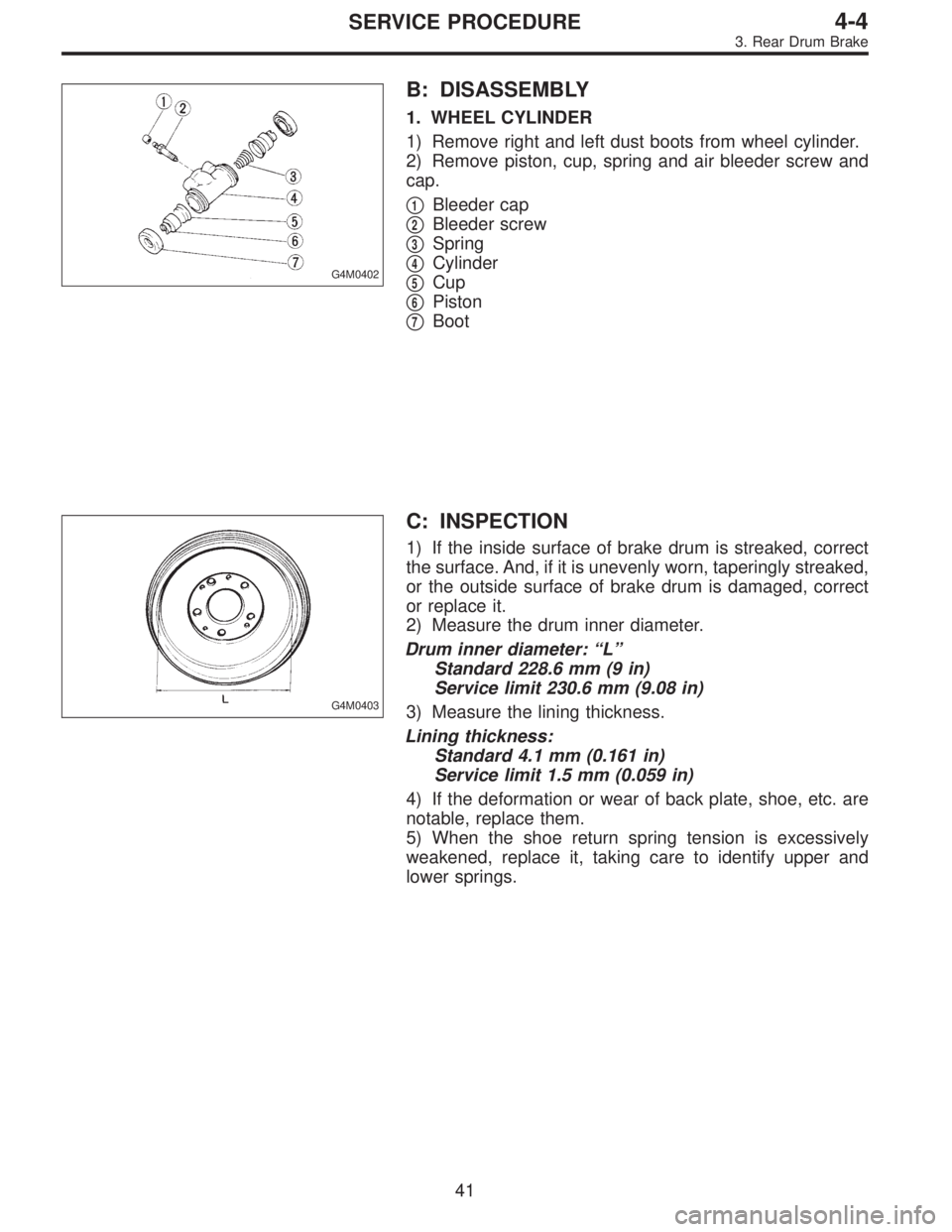
B: DISASSEMBLY
1. WHEEL CYLINDER
1) Remove right and left dust boots from wheel cylinder.
2) Remove piston, cup, spring and air bleeder screw and
cap.
�
1Bleeder cap
�
2Bleeder screw
�
3Spring
�
4Cylinder
�
5Cup
�
6Piston
�
7Boot
G4M0403
C: INSPECTION
1) If the inside surface of brake drum is streaked, correct
the surface. And, if it is unevenly worn, taperingly streaked,
or the outside surface of brake drum is damaged, correct
or replace it.
2) Measure the drum inner diameter.
Drum inner diameter: “L”
Standard 228.6 mm (9 in)
Service limit 230.6 mm (9.08 in)
3) Measure the lining thickness.
Lining thickness:
Standard 4.1 mm (0.161 in)
Service limit 1.5 mm (0.059 in)
4) If the deformation or wear of back plate, shoe, etc. are
notable, replace them.
5) When the shoe return spring tension is excessively
weakened, replace it, taking care to identify upper and
lower springs.
41
4-4SERVICE PROCEDURE
3. Rear Drum Brake
Page 1247 of 2890
 Assembly i")
D: ASSEMBLY
1. WHEEL CYLINDER
Clean all parts in brake fluid. Check and replace faulty
parts.
�Cup and boot for damage or fatigue
�Cylinder, piston and spring or damage or rust formation
1) Assembly is the reverse order of disassembly.
G4M0404
(1) When installing the cup, use ST, apply brake fluid
to the frictional surface for smooth installation and pay
attention to cup direction.
(2) STs are available in different sizes.
CAUTION:
�When replacing the repair kit, make sure that the
sizes of cylinder and cup are the same as those which
were replaced.
�Use only the tool of the correct size.
ST: ADAPTER
Applicable size Part No.
17.46 mm (11/16 in) 925460000
19.05 mm (3/4 in) 926460000
CAUTION:
While assembling, be careful to prevent any metal
chip, dust or dirt from entering the wheel cylinder.
G4M0405
2) Apply rubber grease to the boot inside as shown in
Figure.
Grease:
NIGLUBE RX-2 (Part No. 003606000)
CAUTION:
Never use brake grease.
G4M0401
E: INSTALLATION
1. WHEEL CYLINDER
Install wheel cylinder on back plate, and tighten bolts.
Tightening torque:
10±2 N⋅m (1.0±0.2 kg-m, 7.2±1.4 ft-lb)
42
4-4SERVICE PROCEDURE
3. Rear Drum Brake
Page 1263 of 2890
 Drain brake fluid from reservoir of master cylinder.
2) Remove adjusting nut and cable clamp, and disconnect
PHV cable from cable bracket on engine.
3) Detach PHV")
G4M0428
8. Hill Holder
A: REMOVAL
1) Drain brake fluid from reservoir of master cylinder.
2) Remove adjusting nut and cable clamp, and disconnect
PHV cable from cable bracket on engine.
3) Detach PHV cable from clips.
4) Remove cable clamp, and disconnect PHV cable from
PHV stay.
CAUTION:
Carefully protect boots and inner cable from damage
when disconnecting PHV cable.
5) Disconnect brake pipes from PHV.
CAUTION:
�Pay attention not to drop brake fluid onto body
painting since it may dissolve paint.
�Pay attention not to damage hexagonal head of flare
nut by using pipe wrench without fail.
6) Detach PHV along with support from side frame.
CAUTION:
Exercise utmost care to prevent foreign matter from
entering into PHV when removing it.
B: INSPECTION
Check up removed parts as follows, and replace defective
ones.
1) Check if boots of PHV cable are damaged or degraded,
and if inner cable is damaged or corroded.
2) Check if return spring is worn out, damaged or cor-
roded.
3) Confirm that rolling sound of ball is heard with PHV
inclined and lever rotates smoothly.
CAUTION:
Never disassemble PHV. Replace entire PHV assembly
if necessary.
57
4-4SERVICE PROCEDURE
8. Hill Holder
 Apply a coat of specified grease to boot and fit in groove
on ends of cylinder and piston.
Grease:
NIGLUBE RX-2 (Part No. 003606000)
To facilitate installation, fit boot starting with pisto")
 Clean caliper body interior using brake fluid.
2) Apply a coat of brake fluid to piston seal and fit piston
seal in groove on caliper body.
3) Apply a coat of brake fluid to the entire")