Page 2 of 2890
SPECIFICATIONS
[s21o1
1-1
2
.
Station
Wagon
10
.
WEIGHT
Model
AWD
POST
4AT
Curb
weight
(C
.W
.)
Front
kg
(1b)
748
(1,650)
Rear
kg
(1b)
619
(1,365)
Total
kg
(1b)
1,367
(3,015)
Gross
vehicle
weight
Front
kg
(1b)
936
(2,065)
(G
.V
.W
.)
Rear
kg
(1b)
9S9
(2,180)
Total
kg
(1b)
1,925
(4,245)
NOTE
:
Includes
the
weights
of
power
window,
power
door
lock
and
air
conditioning
in
the
curb
weight
.
Page 179 of 2890

WIRING
DIAGRAM
[113so31
6-3
6
.
Wiring
Diagram
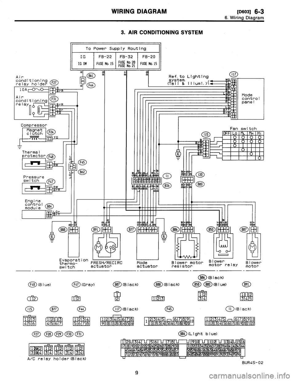
3
.
AIR
CONDITIONING
SYSTEM
Air
conditioningrelay
holder
F27
Compressor
Magnet
F24
clutch
Thermal
protector
F48
Pressure
switch
Q47
Engine
control
module
l
a
p
To
Power
Supply
Routing
IG
FB-22
FB-32
FB-20
IG
SW
FUSE
Na
15
FUSE
Na20FUSENa
21
FUSE
Na
15
M
11
Evaporation
thermo-
FRESH/RECIRC
switch
actuator
F48
(B
I
ue)
(j~)
(Gr
ay)
(M
FIT2-1
123
45
6
C1-
F2~
n
R3
[4151617
1
234
(~D(~D(~D
(~~D
(E)
j
F1W2-1
1
2
1
2
1
2
1
2-
-
-
MMMM
F3T
i
0
9
4
1
3
4
34
34
34
A/Crelay
holder(Black)
Mode
actuator
Ref
.
to
Lighting
Blower
motor
Blower
resistor
motor
relay
O
(B
I
ac
k)
Blower
motor
B87
(B
I
ac
k)
O
(B
I
ac
k)
B50880
(B
I
ue)
B91
1
12
1
2
123
34
345
i
ll
(B
I
ac
k)F45
1
l
(B
I
ac
k)
1
234S
I
6
1
7
1
12345
b789
125
6789(0
34
I1121314t516171819202122
1
9
1
10
1
11
1
12
1
13
1
14
1
15
1
t6
111121314t51617t81920~~
BB4
(L
t
ght
b
I
ue)
12U34
U
56
U
78
U
U
9l0
U
Ilt2
U
1314LJ1516
17
1
18
1
19
1
20
1
21
1
22
1
23
1
24
1
25
1
26
1
27
1
28
1
29
1
30
1
31323
3
34
35
3637
38
39
40
4142
43
44454647
1
48
1
49
~
0
1
51
1
52
1
53
1
54
~
5
1
56
1
57
1
M59
1
60
1
61
~
2
1
63
1
64
1
65
1
66
1
67
1
66
1
69
1
7'
7172
73
74
75
76777B7980
81
1
89
1
83
1
84
8
86878889
90
9192
93
94
996
BUR45-02
9
Page 183 of 2890
WIRING
DIAGRAM
(D6013]
6-3
6
.
Wiring
Diagram
Data
link
connector
Test
mode
B78
B75
~
B76
r
J
-j
mm
C
0
J
4
m
1Ref
.
to
Air
/conditioning
system
.
1Ref
.to
Radiator
~-----s
/
f
an
system
.
10
.
ef
.
toAT
control
R
system,
/L
a
F
m
3
L
o
P
~t
P
O
Engine
B86
control
module
m
M
s
D
j
i
E
v
v
.
.
.
.
l
J
"
-
N
819
8l
BIB
~
B19
f
~
T5
..
..
a
""
CD
Pressure
Front
sources
oxygenswitching
sensor,
~~
i
A
.,n
;H
B75
(Green)
2
Bt8
(Dark
gray)
21
3
CF
Rear
oxygensensor
(California
model)
Rear
oxygensensor
valve
(Othermodels)
B76
(Green)
Bl
(Brown)
Bl9
T6
(Grey)
878
(Y
e
II
ow)
IFNI
12
75
56789
B40
(Grey)
(BBD
(L
i
ghtb
I
ue)
12345678
910111213141516
1
23
4
56
7
8
9
l0
U
l213
14
15
16
17
1819
20
1
22232426
27
28
293
03
132
33
343
5
3637
38
39
4
0
4142
43
44
45
1
46
1
47
1
48
1
49
1
5051
253
54
S5
56S7
5
859
60616
263
64656661
6869
70
71
7273747576777879
80
818283
84
85
1
86
1
87
1
88
1
89
1
90
91
92
93949596
BUR10-02B
13
OBD-1l
service
connector
840
Page 186 of 2890
6-3
[oso2s]
WIRING
DIAGRAM
6
.
Wiring
Diagram
23
.
RADIATOR
FAN
SYSTEM
Diode
(A/C)
Main
fan
motor
oi3~
Subfen
motor
C
~
Flb
(B
leCk)
F43
(Orange)
Fl7
(B
I
ec
K)
(~D(~~(~D
QD
1
2
1
2
[3ql2
4
34
P34
34
A/C
relay
holder(Black)
F44
1234
5678
Engine
control
module
al
I
Air
conditioning
relay
holder
10A
F27
Main
fan
relay-1
F28
Ma
i
nfan
F30
Mr
relay-2
Sub
fan
F29
o
D
relay-2
F45
234
6789
1
1112131415161718192010
884
(L
1
ght
b
I
ue)
12
345678
9l0
lit213141516
17181920212
3242526
78
930
313233343
363738394
4142434445464748
1
49
~
1]
1
51
~
2
15
3
1
54
~
5
56
7
58
59
0
6l
62
63
4
65
66
67
68
9
70
7172
7374
7
76
77
78
79
8
8182
83
84
8
96
87
9
9
192
9394
9
96
BUR14-02
16
Page 271 of 2890
![SUBARU LEGACY 1996 Service Repair Manual
WIRING
DIAGRAM
[D6013]
6-3
6
.
Wiring
Diagram
Data
link
connector
Testmode
878B75
~
B76
YJ
J
~mm
L
J
)
Ref
.
toAir
/
conditioning
system
.
1
Re
f
.to
Radiator
/
fan
system
.
Ref
.
toAT
control SUBARU LEGACY 1996 Service Repair Manual
WIRING
DIAGRAM
[D6013]
6-3
6
.
Wiring
Diagram
Data
link
connector
Testmode
878B75
~
B76
YJ
J
~mm
L
J
)
Ref
.
toAir
/
conditioning
system
.
1
Re
f
.to
Radiator
/
fan
system
.
Ref
.
toAT
control](/manual-img/17/57433/w960_57433-270.png)
WIRING
DIAGRAM
[D6013]
6-3
6
.
Wiring
Diagram
Data
link
connector
Testmode
878B75
~
B76
YJ
J
~mm
L
J
)
Ref
.
toAir
/
conditioning
system
.
1
Re
f
.to
Radiator
/
fan
system
.
Ref
.
toAT
control
J
system
.
L
F
d'
3L
a0J
mo
O
~VI~
f~
MP
Enginecontro
I
BB4
module
m
>rCD
J3
3
F
.
.
..
--
~
-
S
'
K
J
'
B19
'-
818
v
--
Bl9
rl
CE
r
......
T5
~
..
....
T6
Front
Pressure
sources
oxygen
switchfr
sensor
~
.,
i
o
.,
.
B75
(Green)
2
B78
(Ye
I
low)
12
34
56789
Rear
oxygen
sensor
(California
model)
876
(Green)
2
Rear
oxygensensor
(Other
models)
Bl
(Brown)
12
818
(De
rk
gray)
21
3
OBD-
11
service
connector
N~
BGO
valve
9
(Gray)
T6
Bl9
21
43
840
(Gray)
B84
(L
1
ght
b
I
ue)
1
2
34
56
78
9l0
llt213141516
1
1
1
2
1
3
1
4
1
5
1
6
1
7
8
t718192021222324252627282930
3132
3334
3S
I
36
1
37
1
38
1
39
1
40
1
41
1
44445464748
49
50
5152
535455565758
59
60
6162
1
63
1
64
1
65
1
66
1
67
1
68
1
6
9
70
1
9
1
10
1
11
1
12
1
13
1
14
1
151671
1
72
1
73
1
74
1
75
1
76
1
77
1
78
1
79
1
80
1
81
1
82
1
83
1
84
85
86
87
88
1
89
1
9
0
1,
192
939495
96
BUR10-03B
a
Page 304 of 2890

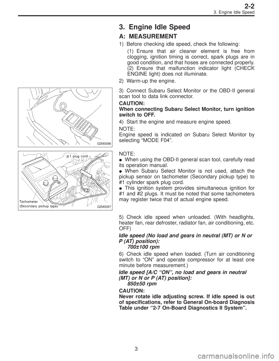
3. Engine Idle Speed
A: MEASUREMENT
1) Before checking idle speed, check the following:
(1) Ensure that air cleaner element is free from
clogging, ignition timing is correct, spark plugs are in
good condition, and that hoses are connected properly.
(2) Ensure that malfunction indicator light (CHECK
ENGINE light) does not illuminate.
2) Warm-up the engine.
G2M0096
3) Connect Subaru Select Monitor or the OBD-II general
scan tool to data link connector.
CAUTION:
When connecting Subaru Select Monitor, turn ignition
switch to OFF.
4) Start the engine and measure engine speed.
NOTE:
Engine speed is indicated on Subaru Select Monitor by
selecting “MODE F04”.
G2M0097
NOTE:
�When using the OBD-II general scan tool, carefully read
its operation manual.
�When Subaru Select Monitor is not used, attach the
pickup sensor on tachometer (Secondary pickup type) to
#1 cylinder spark plug cord.
�This ignition system provides simultaneous ignition for
#1 and #2 plugs. It must be noted that some tachometers
may register twice that of actual engine speed.
5) Check idle speed when unloaded. (With headlights,
heater fan, rear defroster, radiator fan, air conditioning, etc.
OFF)
Idle speed (No load and gears in neutral (MT) or N or
P (AT) position):
700±100 rpm
6) Check idle speed when loaded. (Turn air conditioning
switch to “ON” and operate compressor for at least one
minute before measurement.)
Idle speed [A/C“ON”, no load and gears in neutral
(MT) or N or P (AT) position]:
850±50 rpm
CAUTION:
Never rotate idle adjusting screw. If idle speed is out
of specifications, refer to General On-board Diagnosis
Table under “2-7 On-Board Diagnostics II System”.
3
2-2
3. Engine Idle Speed
Page 400 of 2890
2. Timing Belt
A: REMOVAL
1. CRANKSHAFT PULLEY AND BELT COVER
B2M0684A
G2M0711
1) Remove V-belt cover, V-belt and air conditioning com-
pressor drive belt tensioner.
2) Remove pulley bolt. To lock crankshaft, use ST.
ST 499977000 CRANKSHAFT PULLEY WRENCH
3) Remove crankshaft pulley.
B2M0729
4) Remove left-hand belt cover.
12
2-3bSERVICE PROCEDURE
2. Timing Belt
Page 1375 of 2890

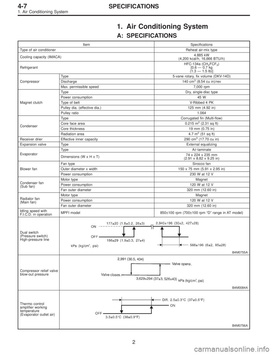
1. Air Conditioning System
A: SPECIFICATIONS
Item Specifications
Type of air conditionerReheat air-mix type
Cooling capacity (IMACA)4.885 kW
(4,200 kcal/h, 16,666 BTU/h)
RefrigerantHFC-134a (CH
2FCF3)
[0.6 — 0.7 kg
(1.3 — 1.5 lb)]
CompressorType 5-vane rotary, fix volume (DKV-14D)
Discharge 140 cm
3(8.54 cu in)/rev
Max. permissible speed 7,000 rpm
Magnet clutchTy p eDry, single-disc type
Power consumption 45 W
Type of belt V-Ribbed 4 PK
Pulley dia. (effective dia.) 125 mm (4.92 in)
Pulley ratio1.064
CondenserType Corrugated fin (Multi-flow)
Core face area 0.215 m
2(2.31 sq ft)
Core thickness 19 mm (0.75 in)
Radiation area 4.7 m
2(51 sq ft)
Receiver drier Effective inner capacity 290 cm3(17.70 cu in)
Expansion valve TypeExternal equalizing
EvaporatorTy p eA�-laminate
Dimensions (W x H x T)74 x 224 x 235 mm
(2.91 x 8.82 x 9.25 in)
Blower fanFan typeSirocco fan
Outer diameter x width 150 x 75 mm (5.91 x 2.95 in)
Power consumption 230 W at 12 V
Condenser fan
(Sub fan)Motor typeMagnet
Power consumption 120 W at 12 V
Fan outer diameter 320 mm (12.60 in)
Radiator fan
(Main fan)Motor typeMagnet
Power consumption 120 W at 12 V
Fan outer diameter 320 mm (12.60 in)
Idling speed with
F.I.C.D. in operationMPFI model 850±100 rpm (700±100 rpm “D” range in AT model)
Dual switch
(Pressure switch)
High-pressure line
B4M0755A
Compressor relief valve
blow-out pressure
B4M0084A
Thermo control
amplifier working
temperature
(Evaporator outlet air)
B4M0756A
2
4-7SPECIFICATIONS
1. Air Conditioning System