Page 321 of 2890
G2M0198
4) Manually push valve rocker (at lash adjuster location) to
check that there is no air in it.
NOTE:
When air is in lash adjuster, valve rocker moves when
pushed with fingers.
G2M0199
5) If air is in lash adjuster, remove valve rocker assembly
from engine and bleed air completely.
B2M0382A
B: AIR BLEEDING
1) Remove valve rocker assembly.
(1) Remove bolts�
1through�4in numerical
sequence.
CAUTION:
Leave two or three threads of bolt�
1engaged to retain
valve rocker assembly.
(2) Equally loosen bolts�
5through�8all the way,
being careful that knock pin is not gouged.
2) Manually remove lash adjusters where air is trapped.
CAUTION:
If lash adjuster is difficult to remove manually, use pli-
ers. Be careful not to scratch lash adjuster.
12
2-3SERVICE PROCEDURE
2. Hydraulic Lash Adjuster
Page 322 of 2890
 Bleed air from hydraulic lash adjuster as described
below:
(1) While dipping hydraulic lash adjuster in engine oil,
as shown in Figure, push check ball in usinga2mm
(0.08 in) diameter round")
G2M0131
3) Bleed air from hydraulic lash adjuster as described
below:
(1) While dipping hydraulic lash adjuster in engine oil,
as shown in Figure, push check ball in usinga2mm
(0.08 in) diameter round bar.
(2) With check ball pushed in, manually move plunger
up and down at one second intervals until air bubbles
disappear.
(3) After air bubbles disappear, remove round bar and
quickly push plunger in to ensure it is locked. If plunger
does not lock properly, replace hydraulic lash adjuster.
CAUTION:
Leave hydraulic lash adjuster (after air is bled) in
engine oil until it is ready for installation.
G2M0200
4) Using ST;
(1) Insert lash adjuster into ST, and fill ST with engine
oil. Usinga2mm(0.08 in) diameter rod, push check
ball in.
ST 499597000 OIL SEAL GUIDE
(2) With check ball pushed in, push plunger at an inter-
val of one second.
(3) Move plunger up and down until air bubbles are no
longer emitted from lash adjuster.
NOTE:
Hold hydraulic lash adjusters vertically during air bleeding.
5) Remove the rod. Push plunger to ensure that air is
completely bled out.
CAUTION:
If plunger does not properly lock (when pushed),
replace lash adjuster with a new one.
13
2-3SERVICE PROCEDURE
2. Hydraulic Lash Adjuster
Page 323 of 2890
 Fill rocker arm’s oil reservoir with engine oil and install
lash adjuster.
CAUTION:
�Do not rotate lash adjuster during installation.
�Be careful not to scratch the oil seal.
B2M0414
CAUTION:
Whe")
6) Fill rocker arm’s oil reservoir with engine oil and install
lash adjuster.
CAUTION:
�Do not rotate lash adjuster during installation.
�Be careful not to scratch the oil seal.
B2M0414
CAUTION:
When removing valve rocker assembly, keep the
assembly soaked in engine oil, or position it with air
bleeding orifice on rocker arm facing upward as
shown. This prevents oil leakage from and air entering
into the hydraulic lash adjuster. Failure to do so may
cause air to enter the hydraulic lash adjuster, causing
loss in performance.
B2M0382B
7) Temporarily and equally tighten bolts�1through�4.Do
not allow knock pin to catch valve rocker assembly.
8) Tighten bolts�
5through�8to specified torque.
9) Tighten bolts�
1through�4to specified torque.
Tightening torque:
12±1 N⋅m (1.2±0.1 kg-m, 8.7±0.7 ft-lb)
10) Install rocker covers.
Tightening torque:
5±1 N⋅m (0.5±0.1 kg-m, 3.6±0.7 ft-lb)
11) Connect harness connectors, hoses, etc. to their posi-
tions.
14
2-3SERVICE PROCEDURE
2. Hydraulic Lash Adjuster
Page 337 of 2890
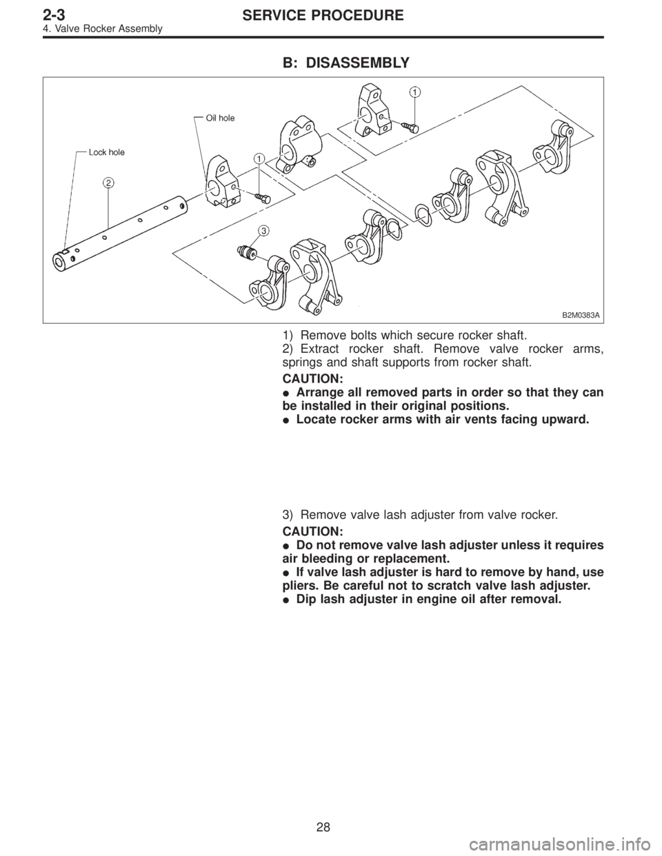
B: DISASSEMBLY
B2M0383A
1) Remove bolts which secure rocker shaft.
2) Extract rocker shaft. Remove valve rocker arms,
springs and shaft supports from rocker shaft.
CAUTION:
�Arrange all removed parts in order so that they can
be installed in their original positions.
�Locate rocker arms with air vents facing upward.
3) Remove valve lash adjuster from valve rocker.
CAUTION:
�Do not remove valve lash adjuster unless it requires
air bleeding or replacement.
�If valve lash adjuster is hard to remove by hand, use
pliers. Be careful not to scratch valve lash adjuster.
�Dip lash adjuster in engine oil after removal.
28
2-3SERVICE PROCEDURE
4. Valve Rocker Assembly
Page 340 of 2890
D: ASSEMBLY
B2M0383B
Tightening torque: N⋅m (kg-m, ft-lb)
T: 5±1 (0.5±0.1, 3.6±0.7)
1) After bleeding air from hydraulic lash adjuster, position
hydraulic lash adjuster in valve rocker arm while dipping in
engine oil.
CAUTION:
�Fill rocker arm oil reservoir chamber with engine oil.
�Install a new hydraulic lash adjuster O-ring, being
careful not to scratch it.
�Do not attempt to rotate hydraulic lash adjuster dur-
ing installation.
2) Arrange valve rocker arms, springs and shaft supports
in assembly order and insert valve rocker shaft. Ensure
that cutout portion of rocker shaft faces oil holes�
Ain shaft
supports.
CAUTION:
Valve rocker arms, rocker shaft and shaft supports
have identification marks. Ensure parts with same
markings are properly assembled.
3) Install valve rocker shaft securing bolts while aligning
shaft“lock”holes�
Bwith bolts.
31
2-3SERVICE PROCEDURE
4. Valve Rocker Assembly
Page 1188 of 2890
 Fee")
10. Power Steering Fluid
A: RECOMMENDED AIR BLEEDING AND
POWER STEERING FLUID
Recommended power steering fluid Manufacturer
ATF DEXRON II or ATF DEXRON IIEB.P.
CALTEX
CASTROL
MOBIL
SHELL
TEXACO
1) Feed the specified fluid with its level being about 5 cm
(2.0 in) lower than the mouth of tank.
2) Continue to turn steering wheel slowly from lock to lock
until bubbles stop appearing in the tank while keeping the
fluid at that level.
3) In case air is absorbed to deliver bubbles into piping
because the fluid level is lower, leave it about half an hour
and then do the step 2) all over again.
4) Start, and idle the engine.
5) Continue to turn steering wheel slowly from lock to lock
again until bubbles stop appearing in the tank while keep-
ing the fluid at that level.
It is normal that bubbles stop appearing after three times
turning of steering wheel.
6) In case bubbles do not stop appearing in the tank, leave
it about half an hour and then do the step 5) all over again.
7) Stop the engine, and take out safety stands after jack-
ing up vehicle again.
Then lower the vehicle, and idle the engine.
8) Continue to turn steering wheel from lock to lock until
bubbles stop appearing and change of the fluid level is
within 3 mm (0.12 in).
9) In case the following happens, leave it about half an
hour and then do step 8) again.
(1) The fluid level changes over 3 mm (0.12 in).
(2) Bubbles remain on the upper surface of the fluid.
(3) Grinding noise is generated from oil pump.
81
4-3SERVICE PROCEDURE
10. Power Steering Fluid
Page 1259 of 2890
 Start engine and keep it running un")
G4M0423
5. CHECKING WITH GAUGES
Connect gauges as shown in Figure. After bleeding air from
pressure gauges, proceed to each check.
G4M0746
6. AIR TIGHTNESS CHECK
1) Start engine and keep it running until a vacuum of 66.7
kPa (500 mmHg, 19.69 inHg) = point A is indicated on
vacuum gauge. Do not depress brake pedal.
2) Stop engine and watch the gauge. If the vacuum drop
range is less than 3.3 kPa (25 mmHg, 0.98 inHg) within 15
seconds after stopping engine, brake booster is functioning
properly.
If defective, the cause may be one of those listed below.
�Check valve malfunction
�Leak from vacuum hose
�Leak from the shell jointed portion or stud bolt welded
portion
�Damaged diaphragm
�Leak from valve body seal and bearing portion
�Leak from plate and seal assembly portion
�Leak from poppet valve assembly portion
G4M0747
7. LOADED AIR TIGHTNESS CHECK
1) Start engine and depress brake pedal with pedal force
of 196 N (20 kg, 44 lb). Keep engine running until a vacuum
of 66.7 kPa (500 mmHg, 19.69 inHg) = point B is indicated
on vacuum gauge while the pedal is still depressed.
2) Stop engine and watch vacuum gauge.
If the vacuum drop range is less than 3.3 kPa (25 mmHg,
0.98 inHg) within 15 seconds after stopping engine, brake
booster is functioning properly.
If defective, refer to“AIR TIGHTNESS CHECK”described
above.
53
4-4SERVICE PROCEDURE
6. Brake Booster
Page 1269 of 2890

A: GENERAL RULES FOR EFFECTIVE
BLEEDING
1) Start with the brakes (wheels) connecting to the sec-
ondary chamber of the master cylinder.
2) The time interval betwee")
11. Air Bleeding (Without TCS model)
A: GENERAL RULES FOR EFFECTIVE
BLEEDING
1) Start with the brakes (wheels) connecting to the sec-
ondary chamber of the master cylinder.
2) The time interval between two brake pedal operations
(from the time when the pedal is released to the time when
it is depressed another time) shall be approximately 3 sec-
onds.
3) The air bleeder on each brake shall be released for 1
to 2 seconds.
B: BLEEDING PROCEDURE
CAUTION:
�The FMVSS No. 116, fresh DOT3 or 4 brake fluid
must be used.
�Cover bleeder with waste cloth, when loosening it,
to prevent brake fluid from being splashed over sur-
rounding parts.
�Avoid mixing different brands of brake fluid to pre-
vent degrading the quality of the fluid.
�Be careful not to allow dirt or dust to get into the
reservoir tank.
NOTE:
�During bleeding operation, keep the brake reserve tank
filled with brake fluid to eliminate entry of air.
�Brake pedal operating must be very slow.
�For convenience and safety, it is advisable to have two
man working.
G4M0434
G4M0435
1) Make sure that there is no leak from joints and connec-
tions of the brake system.
2) Fit one end of vinyl tube into the air bleeder and put the
other end into a brake fluid container.
3) Slowly depress the brake pedal and keep it depressed.
Then, open the air bleeder to discharge air together with
the fluid.
Release air bleeder for 1 to 2 seconds.
Next, with the bleeder closed, slowly release the brake
pedal.
Repeat these steps until there are no more air bubbles in
the vinyl tube.
Allow 3 to 4 seconds between two brake pedal operations.
CAUTION:
Cover bleeder with waste cloth, when loosening it, to
prevent brake fluid from being splashed over sur-
rounding parts.
NOTE:
Brake pedal operating must be very slow.
4) Tighten air bleeder securely when no air bubbles are
visible.
62
4-4SERVICE PROCEDURE
11. Air Bleeding (Without TCS model)
 Manually push valve rocker (at lash adjuster location) to
check that there is no air in it.
NOTE:
When air is in lash adjuster, valve rocker moves when
pushed with fingers.
G2M0199
5) If ai")

T: 5±1 (0.5±0.1, 3.6±0.7)
1) After bleeding air from hydraulic lash adjuster, position
hydraulic lash adjuster in valve rocker arm while")