Page 54 of 2890
![SUBARU LEGACY 1996 Service Repair Manual
ON-BOARD
DIAGNOSTICS
II
SYSTEM
[raFi]
2-7
3
.
Diagnosis
System
I
ST
I
1-1
ooaao0000000000oaooo
OBD0669A
I
ST2
00000
I
0
0
(03C03
0
~
00000
;
i~~
C01-
ST1
OBDD057A
9
Using
data
link
connector](/manual-img/17/57433/w960_57433-53.png "SUBARU LEGACY 1996 Service Repair Manual
ON-BOARD
DIAGNOSTICS
II
SYSTEM
[raFi]
2-7
3
.
Diagnosis
System
I
ST
I
1-1
ooaao0000000000oaooo
OBD0669A
I
ST2
00000
I
0
0
(03C03
0
~
00000
;
i~~
C01-
ST1
OBDD057A
9
Using
data
link
connector")
ON-BOARD
DIAGNOSTICS
II
SYSTEM
[raFi]
2-7
3
.
Diagnosis
System
I
ST
I
1-1
ooaao0000000000oaooo
OBD0669A
I
ST2
00000
I
0
0
(03C03
0
~
00000
;
i~~
C01-
ST1
OBDD057A
9
Using
data
link
connector
for
Subaru
select
monitor
and
OBD-II
general
scan
tool
:
(1)
Connect
ST
to
Subaru
select
monitorcable
.
ST
498357200
ADAPTER
CABLE
(2)
Open
the
cover
and
connect
Subaru
select
moni-
torto
data
link
connector
located
in
thelower
portion
of
the
instrument
panel(on
the
driver'sside),to
the
lower
cover
.
CAUTION
:
Do
not
connect
scan
tools
except
for
Subaru
select
mon-
itor
and
OBD-II
general
scan
tool
.
6)
Turn
ignition
switch
to
ON
(engine
OFF)
and
Subaru
select
monitor
switch
to
ON
.
7)
Start
the
engine
.
NOTE
:
Ensure
the
selector
lever
is
placed
in
the
"P"
position
before
starting
.
8)
Using
the
selector
lever
or
shift
lever,
turn
the
"P"
posi-
tion
switch
and
the
"N"
position
switch
to
ON
.
9)
Depress
the
brake
pedal
to
turn
the
brake
switch
ON
.
10)
Keep
engine
speed
in
the
2,500-3,000
rpm
range
for
40
seconds
.
NOTE
:
On
models
without
tachometer,
usethe
Subaru
select
monitor
or
tachometer
(Secondary
pickup
type)
.
11)
Place
the
selector
lever
or
shift
lever
in
the
"D"
posi-
tion
and
drive
the
vehicle
at
5
to
10
km/h
(3to
6
MPH)
.
NOTE
:
On
AWD
vehicles,
release
the
parking
brake
.
F
:
COMPULSORY
VALVE
OPERATION
CHECK
MODE
1
.
SUBARU
SELECT
MONITOR
1)
Prepare
Subaru
select
monitor
and
cartridge
.
ST1
498307500
SELECT
MONITOR
KIT
ST2
498345700
CARTRIDGE
39
Page 315 of 2890
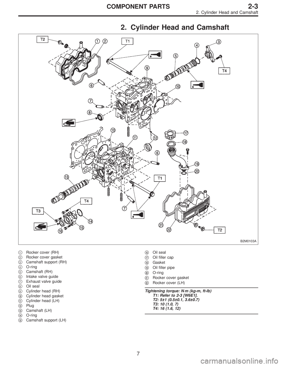
2. Cylinder Head and Camshaft
B2M0103A
�1Rocker cover (RH)
�
2Rocker cover gasket
�
3Camshaft support (RH)
�
4O-ring
�
5Camshaft (RH)
�
6Intake valve guide
�
7Exhaust valve guide
�
8Oil seal
�
9Cylinder head (RH)
�
10Cylinder head gasket
�
11Cylinder head (LH)
�
12Plug
�
13Camshaft (LH)
�
14O-ring
�
15Camshaft support (LH)�
16Oil seal
�
17Oil filler cap
�
18Gasket
�
19Oil filler pipe
�
20O-ring
�
21Rocker cover gasket
�
22Rocker cover (LH)
Tightening torque: N⋅m (kg-m, ft-lb)
T1: Refer to 2-3 [W6E1].
T2: 5±1 (0.5±0.1, 3.6±0.7)
T3: 10 (1.0, 7)
T4: 16 (1.6, 12)
7
2-3COMPONENT PARTS
2. Cylinder Head and Camshaft
Page 323 of 2890
 Fill rocker arm’s oil reservoir with engine oil and install
lash adjuster.
CAUTION:
�Do not rotate lash adjuster during installation.
�Be careful not to scratch the oil seal.
B2M0414
CAUTION:
Whe")
6) Fill rocker arm’s oil reservoir with engine oil and install
lash adjuster.
CAUTION:
�Do not rotate lash adjuster during installation.
�Be careful not to scratch the oil seal.
B2M0414
CAUTION:
When removing valve rocker assembly, keep the
assembly soaked in engine oil, or position it with air
bleeding orifice on rocker arm facing upward as
shown. This prevents oil leakage from and air entering
into the hydraulic lash adjuster. Failure to do so may
cause air to enter the hydraulic lash adjuster, causing
loss in performance.
B2M0382B
7) Temporarily and equally tighten bolts�1through�4.Do
not allow knock pin to catch valve rocker assembly.
8) Tighten bolts�
5through�8to specified torque.
9) Tighten bolts�
1through�4to specified torque.
Tightening torque:
12±1 N⋅m (1.2±0.1 kg-m, 8.7±0.7 ft-lb)
10) Install rocker covers.
Tightening torque:
5±1 N⋅m (0.5±0.1 kg-m, 3.6±0.7 ft-lb)
11) Connect harness connectors, hoses, etc. to their posi-
tions.
14
2-3SERVICE PROCEDURE
2. Hydraulic Lash Adjuster
Page 334 of 2890
G2M0122
1) Installation of timing belt
(1) Using ST, turn left and right camshaft sprockets so
that their alignment marks come to top positions.
ST 499207100 CAMSHAFT SPROCKET WRENCH
B2M0417A
(2) While aligning alignment mark on timing belt with
marks on sprockets, position timing belt properly.
CAUTION:
Ensure belt’s rotating direction is correct.
2) Install belt idler No. 2.
3) Install belt idler.
B2M0111
4) Loosen belt tension adjuster attaching bolts and move
adjuster all the way to the left. Tighten the bolts.
G2M0125
5) After ensuring that the marks on timing belt and cam-
shaft sprockets are aligned, remove stopper pin from belt
tension adjuster.
CAUTION:
After properly installing timing belt, remove rocker
cover and ensure that the valve lash adjuster contains
no air.
25
2-3SERVICE PROCEDURE
3. Timing Belt
Page 336 of 2890
4. Valve Rocker Assembly
A: REMOVAL
B2M0418A
B2M0382A
1) Disconnect PCV hose and remove rocker cover.
2) Removal of valve rocker assembly
(1) Remove bolts�
1through�4in numerical sequence.
CAUTION:
Leave two or three threads of bolt�
1engaged to retain
valve rocker assembly.
(2) Equally loosen bolts�
5through�8all the way, being
careful that knock pin is not gouged.
B2M0414
(3) Remove valve rocker assembly.
CAUTION:
Locate valve rocker assembly with air vent (on rocker
arm) facing upward or dip it in engine oil after removal.
27
2-3SERVICE PROCEDURE
4. Valve Rocker Assembly
Page 341 of 2890
E: INSTALLATION
B2M0418B
Tightening torque: N⋅m (kg-m, ft-lb)
T1: 5±1 (0.5±0.1, 3.6±0.7)
T2: 12±1 (1.2±0.1, 8.7±0.7)
B2M0382B
1) Installation of valve rocker assembly
(1) Temporarily tighten bolts�
1through�4equally as
shown in Figure.
CAUTION:
Do not allow valve rocker assembly to gouge knock
pins.
(2) Tighten bolts�
5through�8to specified torque.
(3) Tighten bolts�
1through�4to specified torque.
2) Install rocker cover and connect PCV hose.
32
2-3SERVICE PROCEDURE
4. Valve Rocker Assembly
Page 350 of 2890
B: DISASSEMBLY
B2M0121A
1) Remove rocker cover.
2) Remove valve rocker assembly.
3) Remove camshaft and support.
4) Place cylinder head on ST.
ST 498267200 CYLINDER HEAD TABLE
B2M0386A
5) Set ST on valve spring. Compress valve spring and
remove the valve spring retainer key. Remove each valve
and valve spring.
ST 499718000 VALVE SPRING REMOVER
CAUTION:
�Mark each valve to prevent confusion.
�Use extreme care not to damage the lips of the
intake valve oil seals and exhaust valve oil seals.
6) Removal of plug (cylinder head LH)
CAUTION:
Do not remove plug unless necessary.
40
2-3SERVICE PROCEDURE
6. Cylinder Head
Page 357 of 2890
B2M0386A
(3) Install valve spring and retainer.
CAUTION:
Be sure to install the valve springs with their close-
coiled end facing the seat on the cylinder head.
(4) Set ST on valve spring.
ST 499718000 VALVE SPRING REMOVER
(5) Compress valve spring and fit valve spring retainer
key.
(6) After installing, tap valve spring retainers lightly
with wooden hammer for better seating.
3) Install camshaft and support.
4) Install valve rocker assembly.
5) Install rocker cover.
47
2-3SERVICE PROCEDURE
6. Cylinder Head
 Installation of timing belt
(1) Using ST, turn left and right camshaft sprockets so
that their alignment marks come to top positions.
ST 499207100 CAMSHAFT SPROCKET WRENCH
B2M0417A
(2) Whil")

T1: 5±1 (0.5±0.1, 3.6±0.7)
T2: 12±1 (1.2±0.1, 8.7±0.7)
B2M0382B
1) Installation of valve rocker assembly
(1) Temporarily tighten b")
![SUBARU LEGACY 1996 Service Repair Manual B: DISASSEMBLY
B2M0121A
1) Remove rocker cover.
2) Remove valve rocker assembly.
<Ref. to 2-3 [W4A0].>
3) Remove camshaft and support.
<Ref. to 2-3 [W5A0].>
4) Place cylinder head on ST.
ST 498267200](/manual-img/17/57433/w960_57433-349.png "SUBARU LEGACY 1996 Service Repair Manual B: DISASSEMBLY
B2M0121A
1) Remove rocker cover.
2) Remove valve rocker assembly.
<Ref. to 2-3 [W4A0].>
3) Remove camshaft and support.
<Ref. to 2-3 [W5A0].>
4) Place cylinder head on ST.
ST 498267200")
 Install valve spring and retainer.
CAUTION:
Be sure to install the valve springs with their close-
coiled end facing the seat on the cylinder head.
(4) Set ST on valve spring.
ST 49971800")