Page 18 of 2890
![SUBARU LEGACY 1996 Service Repair Manual
ON-BOARD
DIAGNOSTICS
II
SYSTEM
[Tiq2]
2-
1
.
General
1~
Engine
control
module
(ECM)
~
Radiator
fan
~2
Ignition
coil~s
Radiator
fan
relay
~3
Ignitqr
~s
Pressure
sources
switching
solenoid
valve
~](/manual-img/17/57433/w960_57433-17.png "SUBARU LEGACY 1996 Service Repair Manual
ON-BOARD
DIAGNOSTICS
II
SYSTEM
[Tiq2]
2-
1
.
General
1~
Engine
control
module
(ECM)
~
Radiator
fan
~2
Ignition
coil~s
Radiator
fan
relay
~3
Ignitqr
~s
Pressure
sources
switching
solenoid
valve
~")
ON-BOARD
DIAGNOSTICS
II
SYSTEM
[Tiq2]
2-
1
.
General
1~
Engine
control
module
(ECM)
~
Radiator
fan
~2
Ignition
coil~s
Radiator
fan
relay
~3
Ignitqr
~s
Pressure
sources
switching
solenoid
valve
~4
Crankshaft
position
sensor
~
Knock
sensor
~5
Camshaft
position
sensor
~
Back-pressure
transducer
Throttle
position
sensor
~s
Front
oxygen
sensor
~7
duel
injectors
~o
Rear
oxygen
sensor
(Except
California
model)
~8
Pressure
regulator
~
Pressure
sensor
Engine
coolant
temperature
sensor
~z
A/C
compressor
~o
Mass
air
flow
sensor
~
Inhibitor
switch
Idle
air
control
solenoid
valve
~
CHECK
ENGINE
malfunction
indicator
lamp
(MIL)
~z
Purge
control
solenoid
valve
~
Tachometer
0
Fuel
pump
~s
A/C
relay
0
PCV
valve
~
A/C
control
module
~s
Air
cleaner
~eIgnition
switch
Canister
~
Transmission
control
module
(TCM)
~
Main
relay
~o
Vehicle
speed
sensor
2
~a
Fuel
pump
relay
~
Data
link
connector
(For
Subaru
select
monitor)
~s
Fuel
filter
@
Data
link
connector
(For
Subaru
select
monitor
and
~o
Front
catalytic
converter
OBD-II
general
scan
tool)
Rear
catalytic
converter
@
Two
way
valve
~2
MGR
valve
~a
Rear
oxygen
sensor
(California
model
only)
EGR
control
solenoid
valve
~
Filter
3
Page 80 of 2890

ON-BOARD
DIAGNOSTICS
II
SYSTEM
[Tyooyl
2-7
10
.
General
Diagnostics
Table
10
.
General
Diagnostics
Table
1
.
FOR
ENGINE
1
23
4
5678
9
10
11
1213
N
ONCdN
C
O
O
a
x
m
Problem
parts
`o
m
v
mj
4'S
O
1>j
T
N
dm
G
~
ON
41
m
~
!d
V
P]
7
0
E
m
~n
N
~o
C
o
O
d
~
~
U
O
c
m~
C
.
.
.
V1
ON
aVa
U
3
C~
0
"
y
dO1OyOQ
~
"O
CN
d7
O
"
0va
l0
0CdyGo
>
"
Vd
da
E
U
"
O
l0
ymC
~
O
NC
N
V
V
4)
N
~
'C
C
.2
7
a
3NmC
oi
mm
o
W
m
.
mU
o~
Symptom
2WFU~Ya
LL
.0
ti
QW
1
Engine
stalls
during
idling
.
O4OOOOO
2
Rough
idling
O
4O
Cl
OO
3
Engine
does
notreturnto
idle
.
O
OO
4Poor
acceleration
O4OOOOO
Engine
stalls
or
engine
sags
or
hesi-
O
D
OOOOOO
fates
at
acceleration
.
6
Surge
O4OOOO
T
Spark
knock
OOOO
8
After
burning
in
exhaust
system
O
Lr
I
O
I
'1
:
The
mark,
D,
indicates
the
symptom
occurring
only
in
cold
temperatures
.
'2
:
For
itemswiththe
mark,
D,ensure
the
secure
installationof
crankshaft
position
sensor
and
camshaft
position
sensor
.
Replacement
is
not
necessary
.
'3
:
Check
fuel
injector,
fuel
pressure
regulator
and
fuel
filter
.
'4
:
Check
ignitor,
ignition
coil
and
spark
plug
.
NOTE
:
Malfunction
of
partsother
than
the
above
is
also
possible
.
Refer
to
1
.
Engine
Trouble
in
General
[K100]
in
Repair
Section
2-3
of
the
Service
Manual
69
Page 300 of 2890
 Remove two screws fixing bracket on fuel pump assem-
bly.
H2M1461A
8) Remove one screw fixing fuel level sensor on bracket.
9) Remove fuel level sensor from fuel pump assembly.
B2M0955A
B:")
H2M1460
7) Remove two screws fixing bracket on fuel pump assem-
bly.
H2M1461A
8) Remove one screw fixing fuel level sensor on bracket.
9) Remove fuel level sensor from fuel pump assembly.
B2M0955A
B: INSTALLATION
CAUTION:
Leave fuel filler cap open when tightening nuts, to pre-
vent fuel from flowing out through fuel delivery and
return pipes. Close fuel filler cap after tightening nuts.
Installation is in the reverse order of removal. Do the fol-
lowing:
(1) Always use new gaskets.
(2) Ensure sealing portion is free from fuel or foreign
particles before installation.
(3) Tighten nuts in numerical sequence shown in Fig-
ure to specified torque.
Tightening torque:
4.4±1.5 N⋅m (0.45±0.15 kg-m, 3.3±1.1 ft-lb)
B2M0968
13. Air Filter (2200 cc AWD Model)
A: REMOVAL AND INSTALLATION
1) Remove canister.
2) Remove two hoses from air filter.
3) Remove flange nut from bracket.
4) Installation is in the reverse order of removal.
16
2-1SERVICE PROCEDURE
12. Fuel Level Sensor (2200 cc AWD Model) - 13. Air Filter (2200 cc AWD Model)
Page 301 of 2890
 Remove two screws fixing bracket on fuel pump assem-
bly.
H2M1461A
8) Remove one screw fixing fuel level sensor on bracket.
9) Remove fuel level sensor from fuel pump assembly.
B2M0955A
B:")
H2M1460
7) Remove two screws fixing bracket on fuel pump assem-
bly.
H2M1461A
8) Remove one screw fixing fuel level sensor on bracket.
9) Remove fuel level sensor from fuel pump assembly.
B2M0955A
B: INSTALLATION
CAUTION:
Leave fuel filler cap open when tightening nuts, to pre-
vent fuel from flowing out through fuel delivery and
return pipes. Close fuel filler cap after tightening nuts.
Installation is in the reverse order of removal. Do the fol-
lowing:
(1) Always use new gaskets.
(2) Ensure sealing portion is free from fuel or foreign
particles before installation.
(3) Tighten nuts in numerical sequence shown in Fig-
ure to specified torque.
Tightening torque:
4.4±1.5 N⋅m (0.45±0.15 kg-m, 3.3±1.1 ft-lb)
B2M0968
13. Air Filter (2200 cc AWD Model)
A: REMOVAL AND INSTALLATION
1) Remove canister.
2) Remove two hoses from air filter.
3) Remove flange nut from bracket.
4) Installation is in the reverse order of removal.
16
2-1SERVICE PROCEDURE
12. Fuel Level Sensor (2200 cc AWD Model) - 13. Air Filter (2200 cc AWD Model)
Page 387 of 2890
TROUBLE
Engine will not start.
Rough idle and engine stall
Low output, hesitation and poor acceleration
Surging
Engine does not return to idle.
Dieseling (Run-on)
After burning in exhaust system
Knocking
Excessive engine oil consumption
Excessive fuel consumption Starter does not turn.
Initial combustion does not occur.
Initial combustion occurs.
Engine stalls after initial combustion.
LUBRICATION SYSTEM
22 3 3�Incorrect oil pressure
2�Loosened oil pump attaching bolts and defective
gasket
2�Defective oil filter seal
2�Defective crankshaft oil seal
32�Defective rocker cover gasket
2�Loosened oil drain plug or defective gasket
2�Loosened oil pan fitting bolts or defective oil pan
COOLING SYSTEM
33221�Overheating
333�Over cooling
OTHERS
113 3�Malfunction of Evaporative Emission Control
System
21�Stuck or damaged throttle valve
322 2�Accelerator cable out of adjustment
77
2-3DIAGNOSTICS
1. Engine Trouble in General
Page 465 of 2890
TROUBLE
Engine will not start.
Rough idle and engine stall
Low output, hesitation and poor acceleration
Surging
Engine does not return to idle.
Dieseling (Run-on)
After burning in exhaust system
Knocking
Excessive engine oil consumption
Excessive fuel consumption Starter does not turn.
Initial combustion does not occur.
Initial combustion occurs.
Engine stalls after initial combustion.
LUBRICATION SYSTEM
22 3 3�Incorrect oil pressure
2�Loosened oil pump attaching bolts and defective
gasket
2�Defective oil filter seal
2�Defective crankshaft oil seal
32�Defective rocker cover gasket
2�Loosened oil drain plug or defective gasket
2�Loosened oil pan fitting bolts or defective oil pan
COOLING SYSTEM
33221�Overheating
333�Over cooling
OTHERS
113 3�Malfunction of Evaporative Emission Control
System
21�Stuck or damaged throttle valve
322 2�Accelerator cable out of adjustment
77
2-3bDIAGNOSTICS
1. Engine Trouble in General
Page 550 of 2890

FUEL SYSTEM2-8
Page
S SPECIFICATIONS AND SERVICE DATA....................................................2
1. Fuel System .............................................................................................2
C COMPONENT PARTS..................................................................................3
1. Fuel Tank ................................................................................................3
2. Fuel Line ..................................................................................................7
W SERVICE PROCEDURE...........................................................................10
1. Precautions ...........................................................................................10
2. On-Car Services ....................................................................................12
3. Fuel Tank ...............................................................................................13
4. Fuel Filler Pipe .......................................................................................16
5. Fuel Filter ..............................................................................................18
6. Fuel Pump ............................................................................................19
7. Fuel Meter Unit .....................................................................................20
8. Fuel Delivery, Return and Evaporation Lines ........................................22
9. Roll Over Valve ......................................................................................25
10. Fuel Sub Meter Unit (AWD model only) ................................................25
11. Fuel Cut Valve (AWD model only) .........................................................26
K DIAGNOSTICS...........................................................................................27
1. Fuel System ...........................................................................................27
Page 551 of 2890
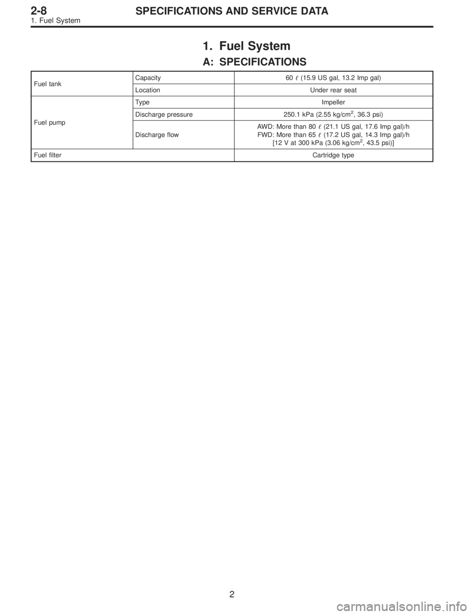
1. Fuel System
A: SPECIFICATIONS
Fuel tankCapacity 60�(15.9 US gal, 13.2 Imp gal)
Location Under rear seat
Fuel pumpType Impeller
Discharge pressure 250.1 kPa (2.55 kg/cm
2, 36.3 psi)
Discharge flowAWD: More than 80�(21.1 US gal, 17.6 Imp gal)/h
FWD: More than 65�(17.2 US gal, 14.3 Imp gal)/h
[12 V at 300 kPa (3.06 kg/cm
2, 43.5 psi)]
Fuel filterCartridge type
2
2-8SPECIFICATIONS AND SERVICE DATA
1. Fuel System

After burning in exhaust system
Knock")

After burning in exhaust system
Knock")