Page 176 of 2890

6-3
[0602
WIRING
DIAGRAM
6
.
Wiring
Diagram
2
.
GROUND
DISTRIBUTION
i26
RedioFront
turn
signal
F3
end
side
marker
rm
light
RH
i
i29
i25
~~--
--
a
--~~
Cigarette
lighter
sB77
Mode
F16
~-~
E
I
actuator
Subfan
motor
i
O
Main
fan
motor
Front
turn
signs
Dend
side
marker
123-1
light
LH
832
Turn
&hazardmodule
Power
wi
relay
AT
shift
lock
857
control
module
(28
:
E
GB-2
FGS
B62
b
:
ill
Combination
meter
(4
m
839
Seat
belt
t
i
mer
C',"-i
F3
(BrowN
O66
(B
I
BC
k)
F19
(Brown)
123
(Brown)
fig
118
(B
I
ac
k)
B43
R15
(B
I
ec
k)
1
2
1
3
1
4
151
6
i
25
1
23
i23
rGlove
box
L~
Illum(nation
light
Fan
switch
L
!-
+'
3
N
NC
i
l7'Z
00
Mode
control
o
panel
0o
~c
'0o
3
il8
4-
L
3
Rear
defoggr
~
o3
switch
O
~m~
07
m
119
Cruise
control
mainswitch
G)§emote
ontro
I
c
LM
rearv
i
e
irror
switch
(g)
(B
I
ec
k)
CD
1
23
4
M
S6
(g)(Brown)
(~D
1
23
[96
R4
;6R7
(~D(BISCK)
(~D
ff~
1516-111
12131><14151
111213
171a191101111121
1718191101111121131141
CD
(L
(ght
gray)
4
'
:F
151617
P911011111~~
D
I
agnos
1
s
Lrm
term
1
na
I
(E~)l
II
um
I
nat
1
on
LEE
contro
I
modu
I
e
(ED
LM
Combination
switch
870
sl=
Combination
switch
B69
Combination
switch
867
-IM
Main
relay
141516
(E)
(a)
1
234
S6JR8
161
r
1
E319
1101
(aD
(B
I
ac
K)
(B
I
u
e)
p
r-1
n
~1
1
F2-1[3
1
f41516
1
7a
0
1
2-
F
-
1q,
[3
46
112-2TI-3114115116117118119120
I'F
BUR04-02A
6
Page 1329 of 2890
B4M1031A
2) Secure relay box connector to connector bracket.
CAUTION:
Align connector with mating receptacle.
3) Using cable clip, secure hydraulic unit harness to relay
box harness.
CAUTION:
Make sure hydraulic unit harness band is secured
beneath cable clip.
4) Connect connector to relay box.
5) Install canister.
6) Install air intake duct.
7) Connect ground cable to battery.
B4M1002
23. ABS Control Module (ABS 5.3 Type)
A: REMOVAL
1. LHD MODEL
1) Turn ignition switch to OFF.
2) Remove front pillar lower trim.
3) Remove glove box.
4) Remove glove box bracket.
B4M1003
5) Remove pocket back panel.
B4M1004
6) Remove bolt from bracket.
11 9
4-4SERVICE PROCEDURE
22. Hydraulic Unit for ABS System (ABS 5.3 Type) - 23. ABS Control Module (ABS 5.3 Type)
Page 1330 of 2890
B4M1031A
2) Secure relay box connector to connector bracket.
CAUTION:
Align connector with mating receptacle.
3) Using cable clip, secure hydraulic unit harness to relay
box harness.
CAUTION:
Make sure hydraulic unit harness band is secured
beneath cable clip.
4) Connect connector to relay box.
5) Install canister.
6) Install air intake duct.
7) Connect ground cable to battery.
B4M1002
23. ABS Control Module (ABS 5.3 Type)
A: REMOVAL
1. LHD MODEL
1) Turn ignition switch to OFF.
2) Remove front pillar lower trim.
3) Remove glove box.
4) Remove glove box bracket.
B4M1003
5) Remove pocket back panel.
B4M1004
6) Remove bolt from bracket.
11 9
4-4SERVICE PROCEDURE
22. Hydraulic Unit for ABS System (ABS 5.3 Type) - 23. ABS Control Module (ABS 5.3 Type)
Page 1366 of 2890
7) Installation is in the reverse order of removal.
Fitted length of heater hose over pipe:
25 — 30 mm (0.98 — 1.18 in)
8) Pour coolant.
B5M0025
3. Blower Motor Assembly
A: REMOVAL AND INSTALLATION
1) Disconnect GND cable from battery.
2) Remove glove box and pocket back panel.
[W1A0].>
3) Disconnect blower motor harness connector.
G4M0555
4) Disconnect aspirator pipe�1.
5) Remove blower motor mounting screw.
6) Remove blower motor assembly.
7) Installation is in the reverse order of removal.
12
4-6SERVICE PROCEDURE
2. Heater Unit - 3. Blower Motor Assembly
Page 1367 of 2890
7) Installation is in the reverse order of removal.
Fitted length of heater hose over pipe:
25 — 30 mm (0.98 — 1.18 in)
8) Pour coolant.
B5M0025
3. Blower Motor Assembly
A: REMOVAL AND INSTALLATION
1) Disconnect GND cable from battery.
2) Remove glove box and pocket back panel.
[W1A0].>
3) Disconnect blower motor harness connector.
G4M0555
4) Disconnect aspirator pipe�1.
5) Remove blower motor mounting screw.
6) Remove blower motor assembly.
7) Installation is in the reverse order of removal.
12
4-6SERVICE PROCEDURE
2. Heater Unit - 3. Blower Motor Assembly
Page 1371 of 2890
B5M0025
5. Intake Door Motor
A: REMOVAL
1) Disconnect GND cable from battery.
2) Remove glove box and pocket back panel.
[W1A0].>
3) Remove heater duct or evaporator. (With A/C model).
G4M0561
4) Remove intake unit from the vehicle.
G4M0562
5) Remove screws which secure intake door motor to
intake unit.
NOTE:
Ensure that RECIRC switch is set to“ON”.
B4M0294A
B: INSPECTION
1) When approx. 12 V is applied to the intake door motor
terminals, intake door motor operates as follows:
LHD model
Intake
door motor
positionTerminal
Intake door motor operation
��
FRESH
32 Door motor moved to FRESH position.
RECIRC 1 Door motor moved to RECIRC position.
RHD model
Intake
door motor
positionTerminal
Intake door motor operation
��
FRESH
21 Door motor moved to FRESH position.
RECIRC 3 Door motor moved to RECIRC position.
16
4-6SERVICE PROCEDURE
5. Intake Door Motor
Page 1412 of 2890
G4M0641
14. Evaporator Unit
A: REMOVAL AND INSTALLATION
1) Disconnect battery negative terminal.
2) Discharge refrigerant using refrigerant recovery system.
3) Disconnect discharge pipe, suction pipe and grommets.
B5M0025
4) Remove glove box and pocket back panel.
[W1A0].>
G4M0642
5) Disconnect the harness connector from evaporator.
6) Disconnect drain hose.
7) Remove evaporator mounting bolt and nut.
8) Install the evaporator in the reverse order of removal.
9) Charge refrigerant.
B4M0099A
B: DISASSEMBLY AND ASSEMBLY
1) Remove resistor assembly�1and remove six screws
from evaporator case.
B4M0100A
2) Remove thermostat�1from upper case. (Thermistor�2
is inserted into specified evaporator fin position.) When
installing thermostat, be sure to insert thermistor into speci-
fied fin position.
37
4-7SERVICE PROCEDURE
14. Evaporator Unit
Page 1566 of 2890
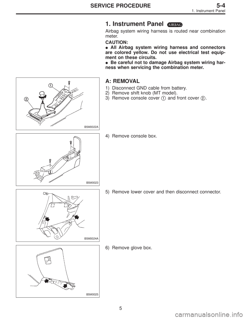
1. Instrument Panel
Airbag system wiring harness is routed near combination
meter.
CAUTION:
�All Airbag system wiring harness and connectors
are colored yellow. Do not use electrical test equip-
ment on these circuits.
�Be careful not to damage Airbag system wiring har-
ness when servicing the combination meter.
B5M0022A
A: REMOVAL
1) Disconnect GND cable from battery.
2) Remove shift knob (MT model).
3) Remove console cover�
1and front cover�2.
B5M0023
4) Remove console box.
B5M0024A
5) Remove lower cover and then disconnect connector.
B5M0025
6) Remove glove box.
5
5-4SERVICE PROCEDURE
1. Instrument Panel
 Secure relay box connector to connector bracket.
CAUTION:
Align connector with mating receptacle.
3) Using cable clip, secure hydraulic unit harness to relay
box harness.
CAUTION:
Make sur")
 Secure relay box connector to connector bracket.
CAUTION:
Align connector with mating receptacle.
3) Using cable clip, secure hydraulic unit harness to relay
box harness.
CAUTION:
Make sur")
![SUBARU LEGACY 1996 Service Repair Manual 7) Installation is in the reverse order of removal.
Fitted length of heater hose over pipe:
25 — 30 mm (0.98 — 1.18 in)
8) Pour coolant. <Ref. to 2-5 [W1B0].>
B5M0025
3. Blower Motor Assembly
A: R](/manual-img/17/57433/w960_57433-1365.png "SUBARU LEGACY 1996 Service Repair Manual 7) Installation is in the reverse order of removal.
Fitted length of heater hose over pipe:
25 — 30 mm (0.98 — 1.18 in)
8) Pour coolant. <Ref. to 2-5 [W1B0].>
B5M0025
3. Blower Motor Assembly
A: R")
![SUBARU LEGACY 1996 Service Repair Manual 7) Installation is in the reverse order of removal.
Fitted length of heater hose over pipe:
25 — 30 mm (0.98 — 1.18 in)
8) Pour coolant. <Ref. to 2-5 [W1B0].>
B5M0025
3. Blower Motor Assembly
A: R](/manual-img/17/57433/w960_57433-1366.png "SUBARU LEGACY 1996 Service Repair Manual 7) Installation is in the reverse order of removal.
Fitted length of heater hose over pipe:
25 — 30 mm (0.98 — 1.18 in)
8) Pour coolant. <Ref. to 2-5 [W1B0].>
B5M0025
3. Blower Motor Assembly
A: R")
![SUBARU LEGACY 1996 Service Repair Manual B5M0025
5. Intake Door Motor
A: REMOVAL
1) Disconnect GND cable from battery.
2) Remove glove box and pocket back panel. <Ref. to 5-4
[W1A0].>
3) Remove heater duct or evaporator. (With A/C model).
<R](/manual-img/17/57433/w960_57433-1370.png "SUBARU LEGACY 1996 Service Repair Manual B5M0025
5. Intake Door Motor
A: REMOVAL
1) Disconnect GND cable from battery.
2) Remove glove box and pocket back panel. <Ref. to 5-4
[W1A0].>
3) Remove heater duct or evaporator. (With A/C model).
<R")
![SUBARU LEGACY 1996 Service Repair Manual G4M0641
14. Evaporator Unit
A: REMOVAL AND INSTALLATION
1) Disconnect battery negative terminal.
2) Discharge refrigerant using refrigerant recovery system.
<Ref. to 4-7 [W601].>
3) Disconnect dischar](/manual-img/17/57433/w960_57433-1411.png "SUBARU LEGACY 1996 Service Repair Manual G4M0641
14. Evaporator Unit
A: REMOVAL AND INSTALLATION
1) Disconnect battery negative terminal.
2) Discharge refrigerant using refrigerant recovery system.
<Ref. to 4-7 [W601].>
3) Disconnect dischar")