Page 290 of 2890
B2M0425A
7. EGR Solenoid Valve
A: REMOVAL AND INSTALLATION
1) Remove bolt which installs EGR solenoid valve onto
intake manifold.
2) Disconnect hoses and connector from EGR solenoid
valve.
NOTE:
This figure shows the rear side of intake manifold.
3) Installation is in the reverse order of removal.
Tightening torque:
19±5 N⋅m (1.9±0.5 kg-m, 13.7±3.6 ft-lb)
G6M0095
8. Fuel Temperature Sensor (2200 cc
AWD Model)
A: REMOVAL
1) Disconnect battery ground cable.
B2M0954A
2) Release fuel pressure.
3) Disconnect fuel delivery hose�
1, return hose�2and jet
pump hose�
3.
B2M0955
4) Remove nuts which install fuel pump assembly onto
fuel tank.
9
2-1SERVICE PROCEDURE
7. EGR Solenoid Valve - 8. Fuel Temperature Sensor (2200 cc AWD Model)
Page 291 of 2890
B2M0425A
7. EGR Solenoid Valve
A: REMOVAL AND INSTALLATION
1) Remove bolt which installs EGR solenoid valve onto
intake manifold.
2) Disconnect hoses and connector from EGR solenoid
valve.
NOTE:
This figure shows the rear side of intake manifold.
3) Installation is in the reverse order of removal.
Tightening torque:
19±5 N⋅m (1.9±0.5 kg-m, 13.7±3.6 ft-lb)
G6M0095
8. Fuel Temperature Sensor (2200 cc
AWD Model)
A: REMOVAL
1) Disconnect battery ground cable.
B2M0954A
2) Release fuel pressure.
3) Disconnect fuel delivery hose�
1, return hose�2and jet
pump hose�
3.
B2M0955
4) Remove nuts which install fuel pump assembly onto
fuel tank.
9
2-1SERVICE PROCEDURE
7. EGR Solenoid Valve - 8. Fuel Temperature Sensor (2200 cc AWD Model)
Page 293 of 2890

B2M0955A
B: INSTALLATION
CAUTION:
Leave fuel filler cap open when tightening nuts, to pre-
vent fuel from flowing out through fuel delivery and
return pipes. Close fuel filler cap after tightening nuts.
Installation is in the reverse order of removal. Do the fol-
lowing:
(1) Always use new gaskets.
(2) Ensure sealing portion is free from fuel or foreign
particles before installation.
(3) Tighten nuts in numerical sequence shown in Fig-
ure to specified torque.
Tightening torque:
4.4±1.5 N⋅m (0.45±0.15 kg-m, 3.3±1.1 ft-lb)
G6M0095
9. Fuel Tank Pressure Sensor (2200 cc
AWD Model)
A: REMOVAL AND INSTALLATION
1) Disconnect battery ground cable.
H2M1122B
2) Remove trims.
�4 door model:
Remove right trunk side trim.
B2M0927A
�Wagon model:
(1) Remove right rear quarter upper rear trim.
(2) Remove right strut cap.
(3) Remove right rear quarter pillar lower trim.
11
2-1SERVICE PROCEDURE
8. Fuel Temperature Sensor (2200 cc AWD Model) - 9. Fuel Tank Pressure Sensor (2200 cc AWD Model)
Page 294 of 2890

B2M0955A
B: INSTALLATION
CAUTION:
Leave fuel filler cap open when tightening nuts, to pre-
vent fuel from flowing out through fuel delivery and
return pipes. Close fuel filler cap after tightening nuts.
Installation is in the reverse order of removal. Do the fol-
lowing:
(1) Always use new gaskets.
(2) Ensure sealing portion is free from fuel or foreign
particles before installation.
(3) Tighten nuts in numerical sequence shown in Fig-
ure to specified torque.
Tightening torque:
4.4±1.5 N⋅m (0.45±0.15 kg-m, 3.3±1.1 ft-lb)
G6M0095
9. Fuel Tank Pressure Sensor (2200 cc
AWD Model)
A: REMOVAL AND INSTALLATION
1) Disconnect battery ground cable.
H2M1122B
2) Remove trims.
�4 door model:
Remove right trunk side trim.
B2M0927A
�Wagon model:
(1) Remove right rear quarter upper rear trim.
(2) Remove right strut cap.
(3) Remove right rear quarter pillar lower trim.
11
2-1SERVICE PROCEDURE
8. Fuel Temperature Sensor (2200 cc AWD Model) - 9. Fuel Tank Pressure Sensor (2200 cc AWD Model)
Page 295 of 2890
B2M0960
3) Disconnect connector from fuel tank pressure sensor.
4) Remove bolts which install fuel tank pressure sensor
bracket on body.
B2M0961
5) Disconnect hose from fuel tank pressure sensor.
6) Remove fuel tank pressure sensor from bracket.
7) Installation is in the reverse order of removal.
G6M0095
10. Pressure Control Solenoid Valve
(2200 cc AWD Model)
A: REMOVAL AND INSTALLATION
1) Disconnect battery ground cable.
2) Lift-up the vehicle.
B2M0962
3) Disconnect evaporation hoses from pressure control
valve.
4) Disconnect connector from pressure control valve.
B2M0963
5) Remove pressure control valve from bracket.
6) Installation is in the reverse order of removal.
12
2-1SERVICE PROCEDURE
9. Fuel Tank Pressure Sensor (2200 cc AWD Model) - 10. Pressure Control Solenoid Valve (2200 cc AWD Model)
Page 296 of 2890
B2M0960
3) Disconnect connector from fuel tank pressure sensor.
4) Remove bolts which install fuel tank pressure sensor
bracket on body.
B2M0961
5) Disconnect hose from fuel tank pressure sensor.
6) Remove fuel tank pressure sensor from bracket.
7) Installation is in the reverse order of removal.
G6M0095
10. Pressure Control Solenoid Valve
(2200 cc AWD Model)
A: REMOVAL AND INSTALLATION
1) Disconnect battery ground cable.
2) Lift-up the vehicle.
B2M0962
3) Disconnect evaporation hoses from pressure control
valve.
4) Disconnect connector from pressure control valve.
B2M0963
5) Remove pressure control valve from bracket.
6) Installation is in the reverse order of removal.
12
2-1SERVICE PROCEDURE
9. Fuel Tank Pressure Sensor (2200 cc AWD Model) - 10. Pressure Control Solenoid Valve (2200 cc AWD Model)
Page 299 of 2890
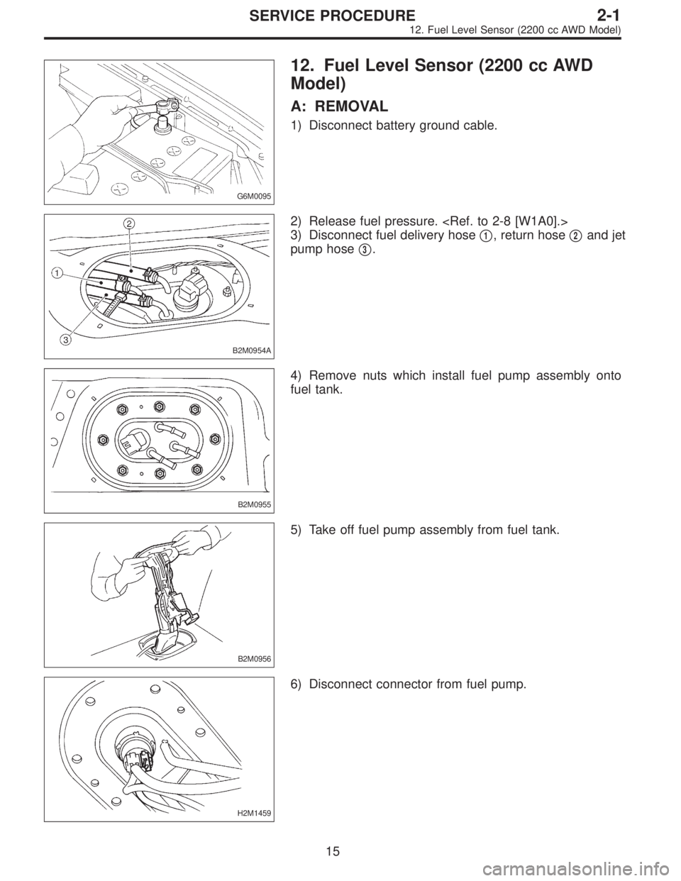
G6M0095
12. Fuel Level Sensor (2200 cc AWD
Model)
A: REMOVAL
1) Disconnect battery ground cable.
B2M0954A
2) Release fuel pressure.
3) Disconnect fuel delivery hose�
1, return hose�2and jet
pump hose�
3.
B2M0955
4) Remove nuts which install fuel pump assembly onto
fuel tank.
B2M0956
5) Take off fuel pump assembly from fuel tank.
H2M1459
6) Disconnect connector from fuel pump.
15
2-1SERVICE PROCEDURE
12. Fuel Level Sensor (2200 cc AWD Model)
Page 562 of 2890
G2M0345
3. Fuel Tank
A: REMOVAL
1) Release fuel pressure.
2) Drain fuel from fuel tank.
G2M0382
3) Remove rear exhaust pipe.
(1) Lift-up the vehicle.
(2) Separate rear exhaust pipe from center exhaust
pipe.
(3) Separate rear exhaust pipe from muffler.
(4) Remove bracket from rubber cushion, and remove
exhaust pipe.
NOTE:
To facilitate the removal of parts, apply a coat of SUBARU
CRC5-56 (Part No. 004301003)
G2M0384
4) Remove muffler assembly.
NOTE:
To facilitate the removal of parts, apply a coat of SUBARU
CRC5-56 (Part No. 004301003)
G3M0059
5) Remove rear differential assembly. (AWD model)
(1) Remove rear axle shafts from rear differential
assembly.
(2) Remove rear differential front cover.
(3) Remove propeller shaft.
(4) Remove lower differential bracket.
(5) Set transmission jack under rear differential.
(6) Remove bolts which install rear differential onto
rear crossmember.
13
2-8SERVICE PROCEDURE
3. Fuel Tank
 Remove bolt which installs EGR solenoid valve onto
intake manifold.
2) Disconnect hoses and connector from EGR solenoid
valve.
NOTE:
This")
 Remove bolt which installs EGR solenoid valve onto
intake manifold.
2) Disconnect hoses and connector from EGR solenoid
valve.
NOTE:
This")
 Disconnect connector from fuel tank pressure sensor.
4) Remove bolts which install fuel tank pressure sensor
bracket on body.
B2M0961
5) Disconnect hose from fuel tank pressure sensor.
6) R")
 Disconnect connector from fuel tank pressure sensor.
4) Remove bolts which install fuel tank pressure sensor
bracket on body.
B2M0961
5) Disconnect hose from fuel tank pressure sensor.
6) R")
![SUBARU LEGACY 1996 Service Repair Manual G2M0345
3. Fuel Tank
A: REMOVAL
1) Release fuel pressure. <Ref. to 2-8 [W1A0].>
2) Drain fuel from fuel tank. <Ref. to 2-8 [W1B0].>
G2M0382
3) Remove rear exhaust pipe.
(1) Lift-up the vehicle.
(2) Se](/manual-img/17/57433/w960_57433-561.png "SUBARU LEGACY 1996 Service Repair Manual G2M0345
3. Fuel Tank
A: REMOVAL
1) Release fuel pressure. <Ref. to 2-8 [W1A0].>
2) Drain fuel from fuel tank. <Ref. to 2-8 [W1B0].>
G2M0382
3) Remove rear exhaust pipe.
(1) Lift-up the vehicle.
(2) Se")