Page 1049 of 2890
G4M0208
1. Wheels and Axles
A: SPECIFICATIONS
1. TIRE AND WHEEL SIZE
Tire size Rim sizeRim offset
mm (in)P.C.D.
mm (in)
Except OUTBACK modelFront and RearP185/70R14
87S14×5 1/2JJ 55 (2.17)
100 (3.94)
dia. P195/60R15
87H15 x 6JJ 55 (2.17)
T-type tireT125/70D15 15 x 4T 53 (2.09)
T135/70D16 16 x 4T 50 (1.97)
OUTBACK modelFront and RearP205/70R15
95S15 x 6JJ 55 (2.17)
T-type tire T135/80D16 16 x 4T 50 (1.97)
NOTE:“T-type”tire for temporary use is supplied as a spare tire.
2. TIRE INFLATION PRESSURE
Tire sizeTire inflation pressure kPa (kg/cm
2, psi)
Light load Full load Trailler towing
Except OUTBACK
modelFront and RearP185/70R14 87S
P195/60R15 87HFt: 220 (2.2, 32)
Rr: 210 (2.1, 30)—
T-type tireT125/70D15
T135/70D16420 (4.2, 60)
OUTBACK modelFront and Rear P205/70R15 95SFt: 200 (2.0, 29)
Rr: 190 (1.9, 28)Ft: 200 (2.0, 2.9)
Rr: 220 (2.2, 32)
T-type tire T135/80D16 420 (4.2, 60)
2
4-2SPECIFICATIONS AND SERVICE DATA
1. Wheels and Axles
Page 1099 of 2890
B4M0051
7. Full Wheel Cap
A: REMOVAL
Pry off the full wheel cap with a wheel cap remover inserted
between openings in the cap.
B: INSTALLATION
Align the valve hole in the wheel cap with the valve on the
wheel and secure the wheel cap by tapping four points by
hand.
8. Steel Wheel and Tire
1) Deformation or damage on the rim can cause air leak-
age. Check the rim flange for deformation, crack, or
damage, and repair or replace as necessary.
2) Take stone, glass, nail etc. off the tread groove.
G4M0297
3) Replace tire:
�when large crack on side wall, damage or crack on
tread is found.
�when the“tread wear indicator”appears as a solid
band across the tread.
CAUTION:
�When replacing a tire, make sure to use only the
same size, construction and load range as originally
installed.
�Avoid mixing radial, belted bias or bias tires on the
vehicle.
49
4-2SERVICE PROCEDURE
7. Full Wheel Cap - 8. Steel Wheel and Tire
Page 1100 of 2890
B4M0051
7. Full Wheel Cap
A: REMOVAL
Pry off the full wheel cap with a wheel cap remover inserted
between openings in the cap.
B: INSTALLATION
Align the valve hole in the wheel cap with the valve on the
wheel and secure the wheel cap by tapping four points by
hand.
8. Steel Wheel and Tire
1) Deformation or damage on the rim can cause air leak-
age. Check the rim flange for deformation, crack, or
damage, and repair or replace as necessary.
2) Take stone, glass, nail etc. off the tread groove.
G4M0297
3) Replace tire:
�when large crack on side wall, damage or crack on
tread is found.
�when the“tread wear indicator”appears as a solid
band across the tread.
CAUTION:
�When replacing a tire, make sure to use only the
same size, construction and load range as originally
installed.
�Avoid mixing radial, belted bias or bias tires on the
vehicle.
49
4-2SERVICE PROCEDURE
7. Full Wheel Cap - 8. Steel Wheel and Tire
Page 1247 of 2890

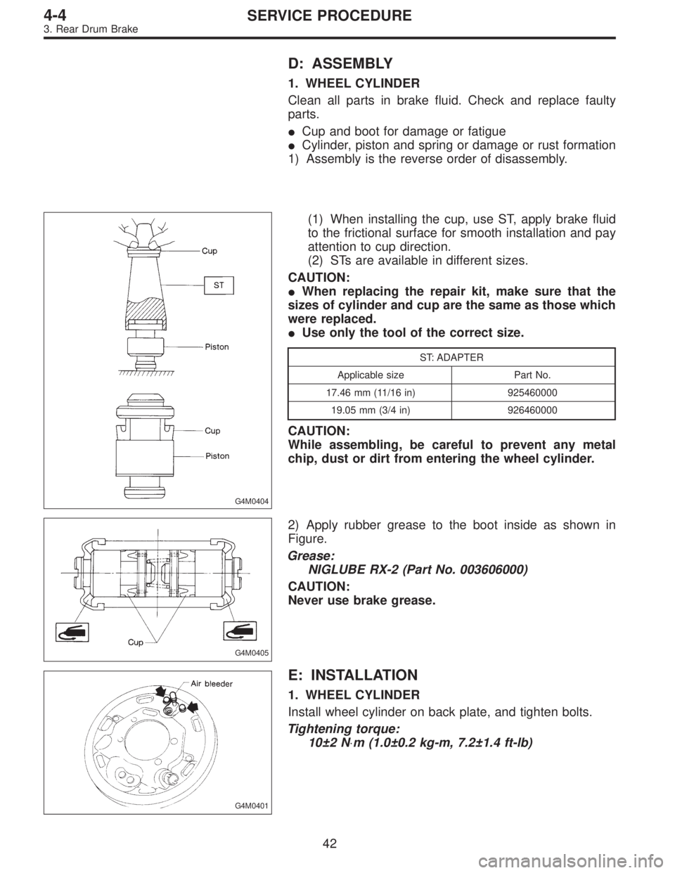
D: ASSEMBLY
1. WHEEL CYLINDER
Clean all parts in brake fluid. Check and replace faulty
parts.
�Cup and boot for damage or fatigue
�Cylinder, piston and spring or damage or rust formation
1) Assembly is the reverse order of disassembly.
G4M0404
(1) When installing the cup, use ST, apply brake fluid
to the frictional surface for smooth installation and pay
attention to cup direction.
(2) STs are available in different sizes.
CAUTION:
�When replacing the repair kit, make sure that the
sizes of cylinder and cup are the same as those which
were replaced.
�Use only the tool of the correct size.
ST: ADAPTER
Applicable size Part No.
17.46 mm (11/16 in) 925460000
19.05 mm (3/4 in) 926460000
CAUTION:
While assembling, be careful to prevent any metal
chip, dust or dirt from entering the wheel cylinder.
G4M0405
2) Apply rubber grease to the boot inside as shown in
Figure.
Grease:
NIGLUBE RX-2 (Part No. 003606000)
CAUTION:
Never use brake grease.
G4M0401
E: INSTALLATION
1. WHEEL CYLINDER
Install wheel cylinder on back plate, and tighten bolts.
Tightening torque:
10±2 N⋅m (1.0±0.2 kg-m, 7.2±1.4 ft-lb)
42
4-4SERVICE PROCEDURE
3. Rear Drum Brake