Page 319 of 2890
G2M0106
1. General Precautions
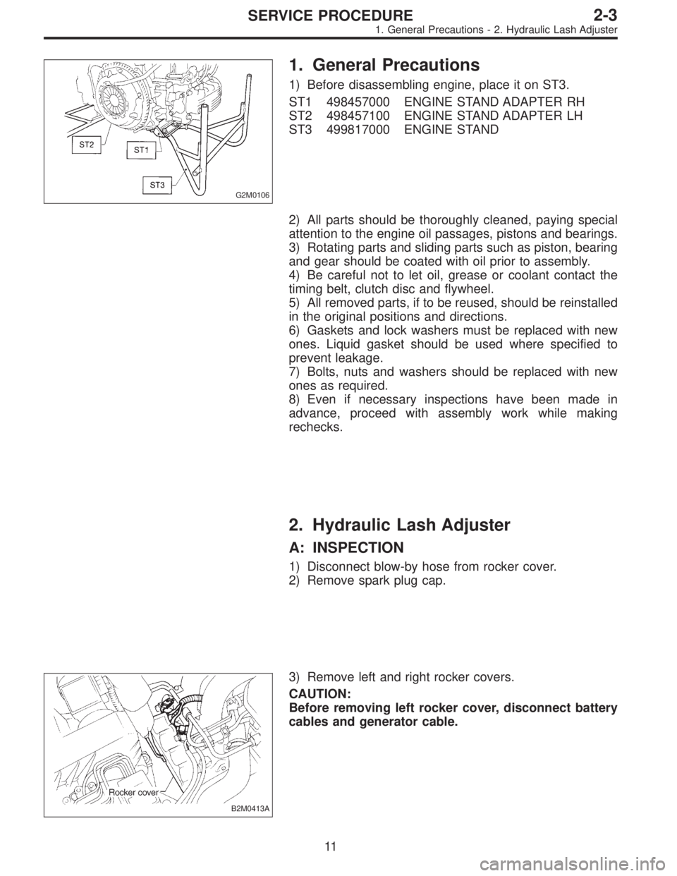
1) Before disassembling engine, place it on ST3.
ST1 498457000 ENGINE STAND ADAPTER RH
ST2 498457100 ENGINE STAND ADAPTER LH
ST3 499817000 ENGINE STAND
2) All parts should be thoroughly cleaned, paying special
attention to the engine oil passages, pistons and bearings.
3) Rotating parts and sliding parts such as piston, bearing
and gear should be coated with oil prior to assembly.
4) Be careful not to let oil, grease or coolant contact the
timing belt, clutch disc and flywheel.
5) All removed parts, if to be reused, should be reinstalled
in the original positions and directions.
6) Gaskets and lock washers must be replaced with new
ones. Liquid gasket should be used where specified to
prevent leakage.
7) Bolts, nuts and washers should be replaced with new
ones as required.
8) Even if necessary inspections have been made in
advance, proceed with assembly work while making
rechecks.
2. Hydraulic Lash Adjuster
A: INSPECTION
1) Disconnect blow-by hose from rocker cover.
2) Remove spark plug cap.
B2M0413A
3) Remove left and right rocker covers.
CAUTION:
Before removing left rocker cover, disconnect battery
cables and generator cable.
11
2-3SERVICE PROCEDURE
1. General Precautions - 2. Hydraulic Lash Adjuster
Page 320 of 2890
G2M0106
1. General Precautions
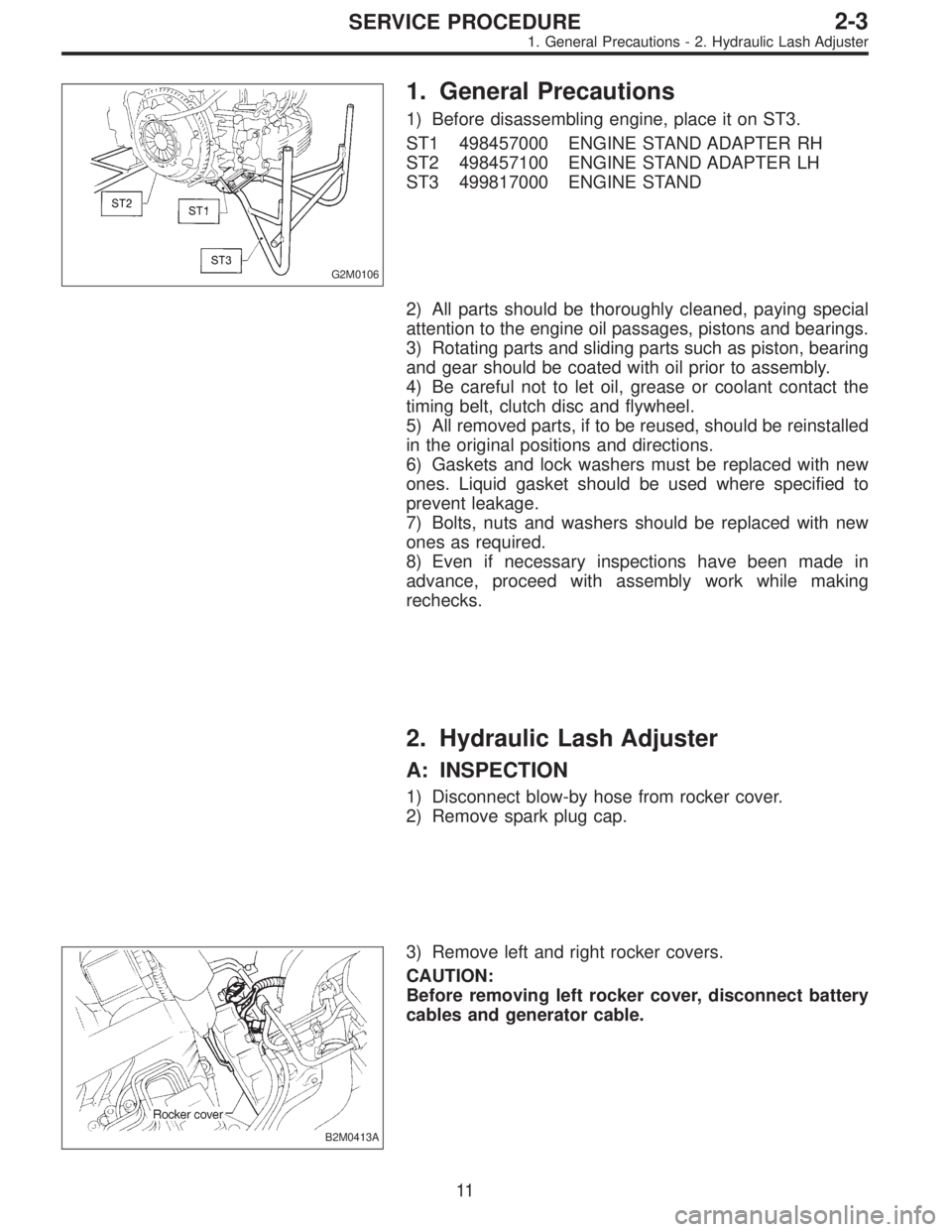
1) Before disassembling engine, place it on ST3.
ST1 498457000 ENGINE STAND ADAPTER RH
ST2 498457100 ENGINE STAND ADAPTER LH
ST3 499817000 ENGINE STAND
2) All parts should be thoroughly cleaned, paying special
attention to the engine oil passages, pistons and bearings.
3) Rotating parts and sliding parts such as piston, bearing
and gear should be coated with oil prior to assembly.
4) Be careful not to let oil, grease or coolant contact the
timing belt, clutch disc and flywheel.
5) All removed parts, if to be reused, should be reinstalled
in the original positions and directions.
6) Gaskets and lock washers must be replaced with new
ones. Liquid gasket should be used where specified to
prevent leakage.
7) Bolts, nuts and washers should be replaced with new
ones as required.
8) Even if necessary inspections have been made in
advance, proceed with assembly work while making
rechecks.
2. Hydraulic Lash Adjuster
A: INSPECTION
1) Disconnect blow-by hose from rocker cover.
2) Remove spark plug cap.
B2M0413A
3) Remove left and right rocker covers.
CAUTION:
Before removing left rocker cover, disconnect battery
cables and generator cable.
11
2-3SERVICE PROCEDURE
1. General Precautions - 2. Hydraulic Lash Adjuster
Page 589 of 2890
1. General
A: PRECAUTION
When servicing clutch system, pay attention to the follow-
ing items.
1. MECHANICAL APPLICATION TYPE
1) Check the routing of clutch cable for smoothness.
2) Excessive tightness or looseness of clutch cable have
a bad influence upon the cable durability.
3) Apply grease sufficiently to the connecting portion of
clutch pedal.
4) Apply grease sufficiently to the release lever portion.
5) Position clutch cable through the center of toe board
hole and route it smoothly. Adjustment is done by moving
the outer cable.
6) Make sure not to let the clutch chatter when starting
forward or rearward. If clutch chattering occurs, readjust so
that the bend of clutch outer cable becomes flatter.
G2M0234
2. On-Car Service
1. MECHANICAL APPLICATION TYPE
1) Remove release lever return spring from lever (Models
without hill holder only).
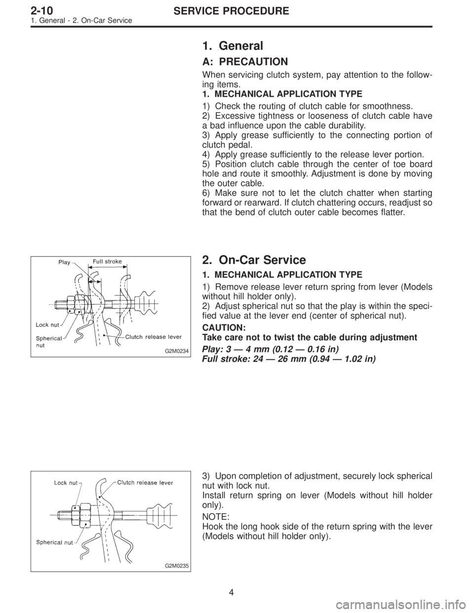
2) Adjust spherical nut so that the play is within the speci-
fied value at the lever end (center of spherical nut).
CAUTION:
Take care not to twist the cable during adjustment
Play: 3 — 4 mm (0.12 — 0.16 in)
Full stroke: 24 — 26 mm (0.94 — 1.02 in)
G2M0235
3) Upon completion of adjustment, securely lock spherical
nut with lock nut.
Install return spring on lever (Models without hill holder
only).
NOTE:
Hook the long hook side of the return spring with the lever
(Models without hill holder only).
4
2-10SERVICE PROCEDURE
1. General - 2. On-Car Service
Page 592 of 2890
B2M0633A
1. MECHANICAL APPLICATION TYPE
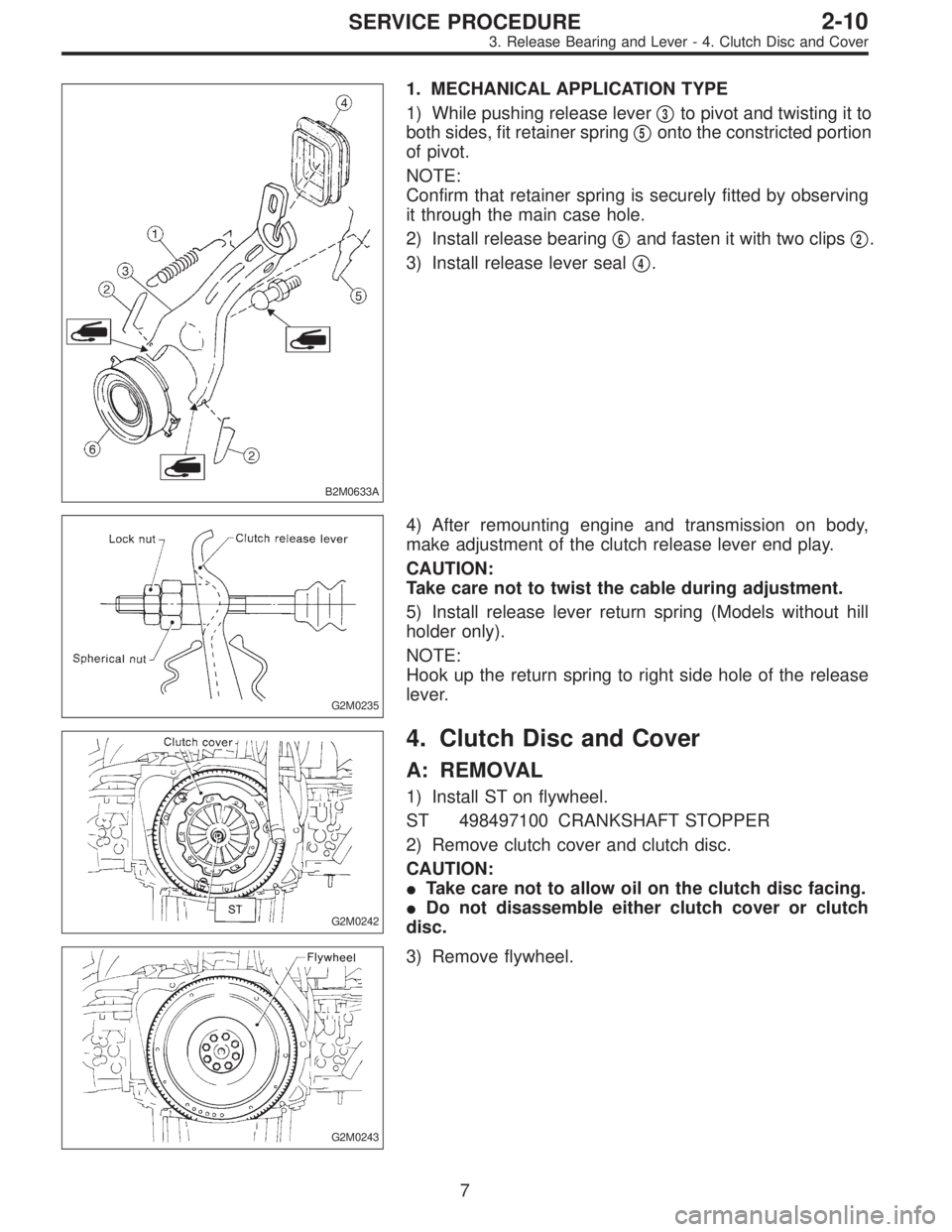
1) While pushing release lever�
3to pivot and twisting it to
both sides, fit retainer spring�
5onto the constricted portion
of pivot.
NOTE:
Confirm that retainer spring is securely fitted by observing
it through the main case hole.
2) Install release bearing�
6and fasten it with two clips�2.
3) Install release lever seal�
4.
G2M0235
4) After remounting engine and transmission on body,
make adjustment of the clutch release lever end play.
CAUTION:
Take care not to twist the cable during adjustment.
5) Install release lever return spring (Models without hill
holder only).
NOTE:
Hook up the return spring to right side hole of the release
lever.
G2M0242
4. Clutch Disc and Cover
A: REMOVAL
1) Install ST on flywheel.
ST 498497100 CRANKSHAFT STOPPER
2) Remove clutch cover and clutch disc.
CAUTION:
�Take care not to allow oil on the clutch disc facing.
�Do not disassemble either clutch cover or clutch
disc.
G2M0243
3) Remove flywheel.
7
2-10SERVICE PROCEDURE
3. Release Bearing and Lever - 4. Clutch Disc and Cover
Page 702 of 2890
1. General
A: PRECAUTION
When servicing clutch system, pay attention to the follow-
ing items.
1. MECHANICAL APPLICATION TYPE
1) Check the routing of clutch cable for smoothness.
2) Excessive tightness or looseness of clutch cable have
a bad influence upon the cable durability.
3) Apply grease sufficiently to the connecting portion of
clutch pedal.
4) Apply grease sufficiently to the release lever portion.
5) Position clutch cable through the center of toe board
hole and route it smoothly. Adjustment is done by moving
the outer cable.
6) Make sure not to let the clutch chatter when starting
forward or rearward. If clutch chattering occurs, readjust so
that the bend of clutch outer cable becomes flatter.
G2M0234
2. On-Car Service
1. MECHANICAL APPLICATION TYPE
1) Remove release lever return spring from lever (Models
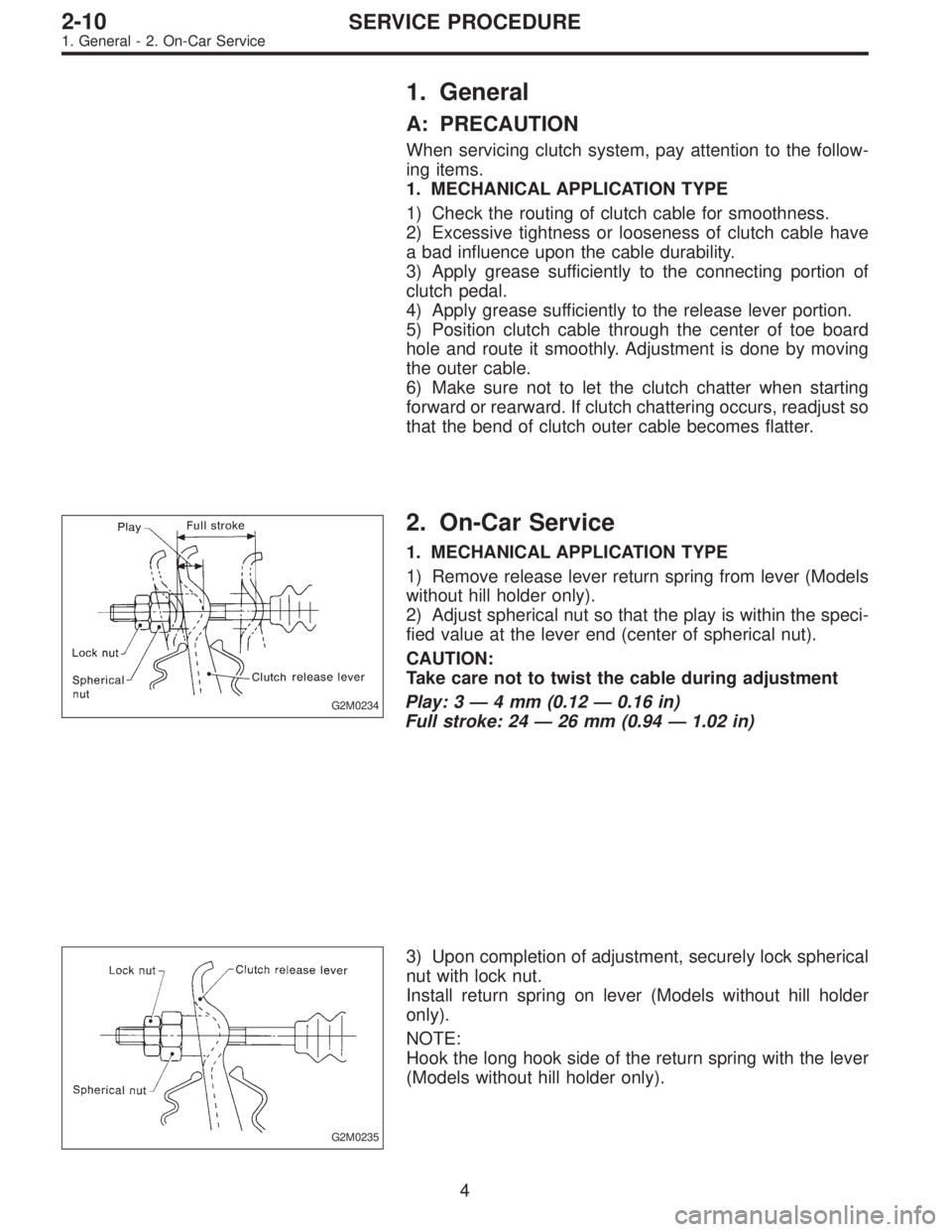
without hill holder only).
2) Adjust spherical nut so that the play is within the speci-
fied value at the lever end (center of spherical nut).
CAUTION:
Take care not to twist the cable during adjustment
Play: 3 — 4 mm (0.12 — 0.16 in)
Full stroke: 24 — 26 mm (0.94 — 1.02 in)
G2M0235
3) Upon completion of adjustment, securely lock spherical
nut with lock nut.
Install return spring on lever (Models without hill holder
only).
NOTE:
Hook the long hook side of the return spring with the lever
(Models without hill holder only).
4
2-10SERVICE PROCEDURE
1. General - 2. On-Car Service
Page 703 of 2890
1. General
A: PRECAUTION
When servicing clutch system, pay attention to the follow-
ing items.
1. MECHANICAL APPLICATION TYPE
1) Check the routing of clutch cable for smoothness.
2) Excessive tightness or looseness of clutch cable have
a bad influence upon the cable durability.
3) Apply grease sufficiently to the connecting portion of
clutch pedal.
4) Apply grease sufficiently to the release lever portion.
5) Position clutch cable through the center of toe board
hole and route it smoothly. Adjustment is done by moving
the outer cable.
6) Make sure not to let the clutch chatter when starting
forward or rearward. If clutch chattering occurs, readjust so
that the bend of clutch outer cable becomes flatter.
G2M0234
2. On-Car Service
1. MECHANICAL APPLICATION TYPE
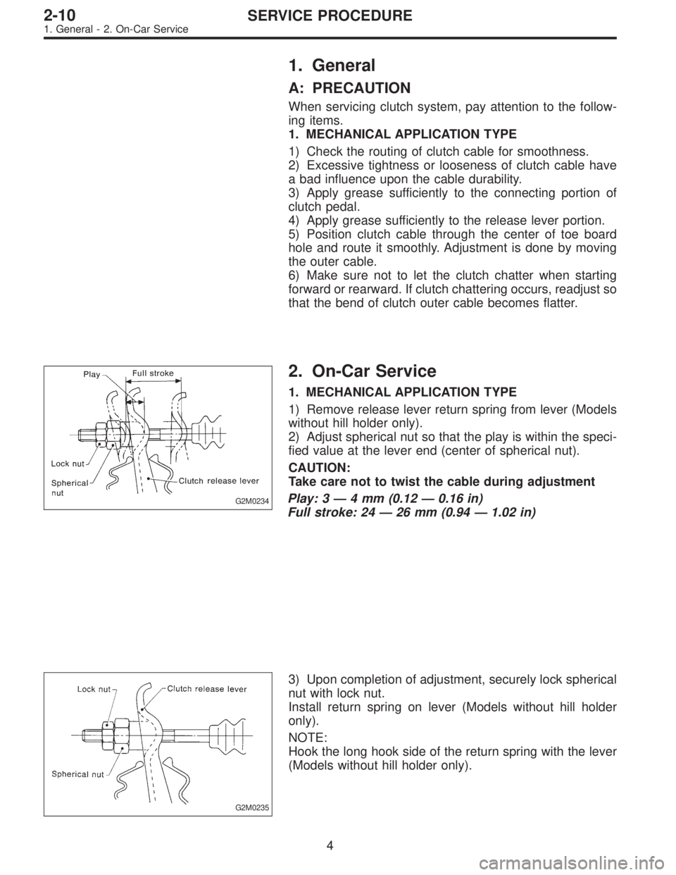
1) Remove release lever return spring from lever (Models
without hill holder only).
2) Adjust spherical nut so that the play is within the speci-
fied value at the lever end (center of spherical nut).
CAUTION:
Take care not to twist the cable during adjustment
Play: 3 — 4 mm (0.12 — 0.16 in)
Full stroke: 24 — 26 mm (0.94 — 1.02 in)
G2M0235
3) Upon completion of adjustment, securely lock spherical
nut with lock nut.
Install return spring on lever (Models without hill holder
only).
NOTE:
Hook the long hook side of the return spring with the lever
(Models without hill holder only).
4
2-10SERVICE PROCEDURE
1. General - 2. On-Car Service
Page 707 of 2890
B2M0633A
1. MECHANICAL APPLICATION TYPE
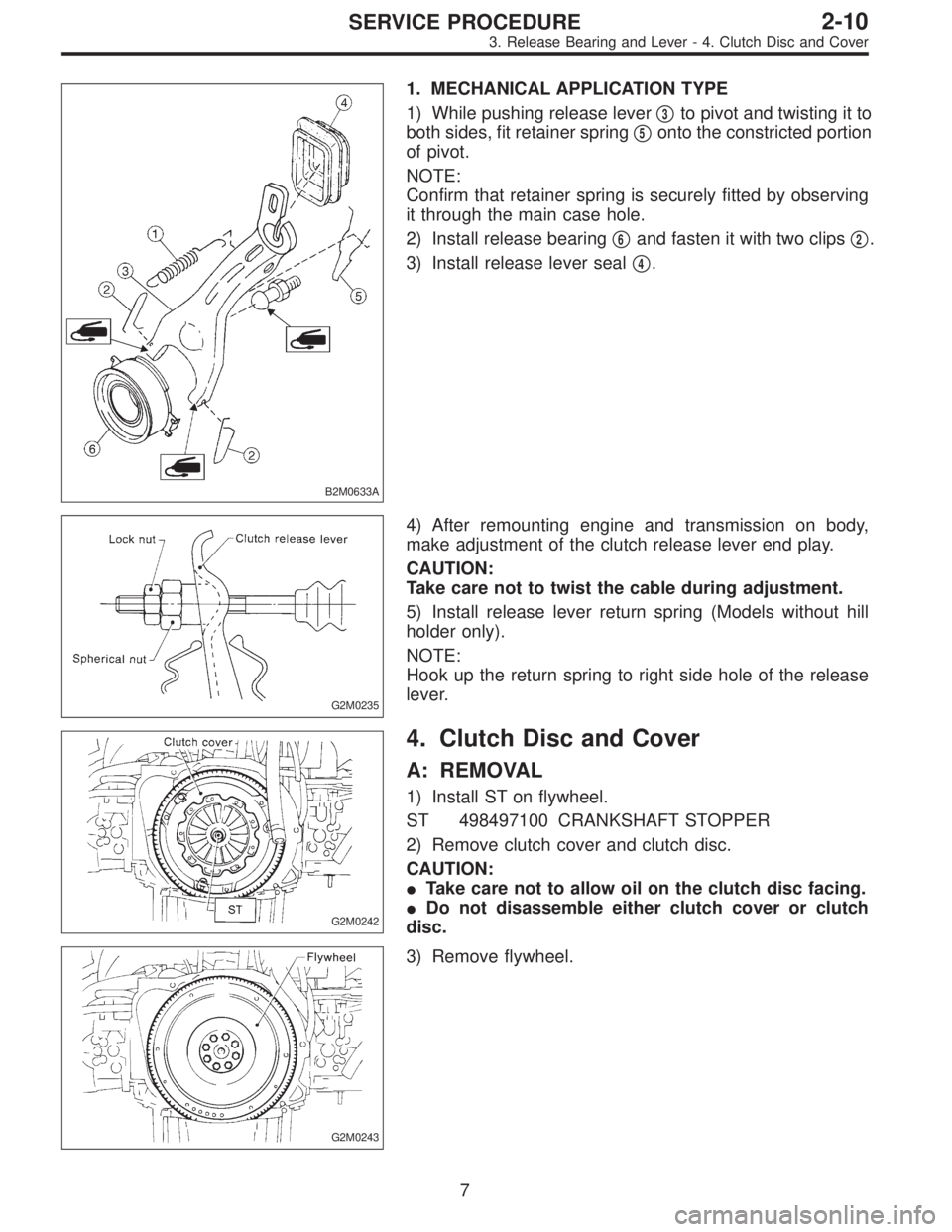
1) While pushing release lever�
3to pivot and twisting it to
both sides, fit retainer spring�
5onto the constricted portion
of pivot.
NOTE:
Confirm that retainer spring is securely fitted by observing
it through the main case hole.
2) Install release bearing�
6and fasten it with two clips�2.
3) Install release lever seal�
4.
G2M0235
4) After remounting engine and transmission on body,
make adjustment of the clutch release lever end play.
CAUTION:
Take care not to twist the cable during adjustment.
5) Install release lever return spring (Models without hill
holder only).
NOTE:
Hook up the return spring to right side hole of the release
lever.
G2M0242
4. Clutch Disc and Cover
A: REMOVAL
1) Install ST on flywheel.
ST 498497100 CRANKSHAFT STOPPER
2) Remove clutch cover and clutch disc.
CAUTION:
�Take care not to allow oil on the clutch disc facing.
�Do not disassemble either clutch cover or clutch
disc.
G2M0243
3) Remove flywheel.
7
2-10SERVICE PROCEDURE
3. Release Bearing and Lever - 4. Clutch Disc and Cover
Page 708 of 2890
B2M0633A
1. MECHANICAL APPLICATION TYPE
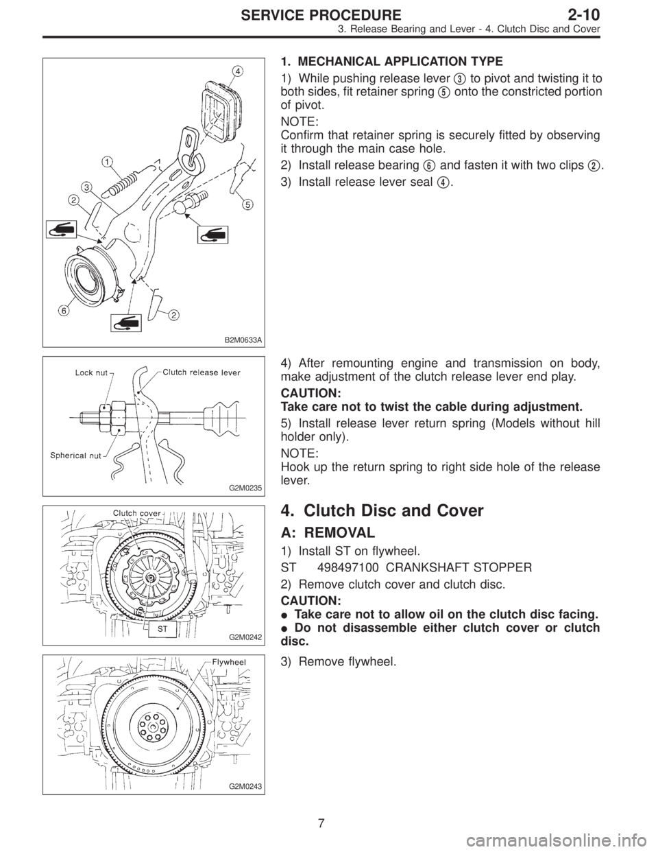
1) While pushing release lever�
3to pivot and twisting it to
both sides, fit retainer spring�
5onto the constricted portion
of pivot.
NOTE:
Confirm that retainer spring is securely fitted by observing
it through the main case hole.
2) Install release bearing�
6and fasten it with two clips�2.
3) Install release lever seal�
4.
G2M0235
4) After remounting engine and transmission on body,
make adjustment of the clutch release lever end play.
CAUTION:
Take care not to twist the cable during adjustment.
5) Install release lever return spring (Models without hill
holder only).
NOTE:
Hook up the return spring to right side hole of the release
lever.
G2M0242
4. Clutch Disc and Cover
A: REMOVAL
1) Install ST on flywheel.
ST 498497100 CRANKSHAFT STOPPER
2) Remove clutch cover and clutch disc.
CAUTION:
�Take care not to allow oil on the clutch disc facing.
�Do not disassemble either clutch cover or clutch
disc.
G2M0243
3) Remove flywheel.
7
2-10SERVICE PROCEDURE
3. Release Bearing and Lever - 4. Clutch Disc and Cover