Page 16 of 2890

5-5b
[W7B1)
SERVICE
PROCEDURE
7
.
Combination
Switch
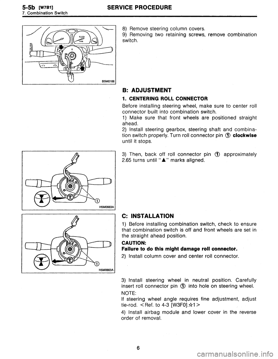
8)
Remove
steering
column
cowers
.
9)
Removing
two
retaining
screws,
remove
combination
switch
.
B
:
ADJUSTMENT
1
.
CENTERING
ROLL
CONNECTOR
Before
installing
steering
wheel,
make
sure
to
center
roil
connector
built
into
combination
switch
.
1)
Make
sure
that
front
wheels
are
positioned
straight
ahead
.
2)
Install
steering
gearbox,
steering
shaft
and
combina-
tion
switchproperly
.
Turn
roll
connector
pin
(J)
clockwise
until
it
stops
.
3)
Then,
back
off
roll
connector
pin
1~
approximately
2
.65
turns
until
"A"
marks
aligned
.
C
:
INSTALLATION
1)
Before
installing
combination
switch,
check
to
ensure
that
combination
switch
is
off
and
font
wheels
are
set
in
the
.straight
ahead
position
.
CAUTION
:
Failure
to
do
this
might
damage
roll
connoctok
.
2)
Install
column
cover
and
center
roll
connector
.
3)
Install
steering
wheel
in
neutral
position
.
Carefully
insert
roll
connector
pin
1(~
into
hole
on
steering
wheel
.
NOTE
:
If
steering
wheel
angle
requires
fine
adjustment,
adjust
tie-rod
.
<
Ref
.
to
4-3
[W3FOj
.*1
>
4)
Install
airbag
module
and
lower
cover
in
the
reverse
order
of
removal
.
6
Page 18 of 2890
![SUBARU LEGACY 1996 Service Repair Manual
ON-BOARD
DIAGNOSTICS
II
SYSTEM
[Tiq2]
2-
1
.
General
1~
Engine
control
module
(ECM)
~
Radiator
fan
~2
Ignition
coil~s
Radiator
fan
relay
~3
Ignitqr
~s
Pressure
sources
switching
solenoid
valve
~ SUBARU LEGACY 1996 Service Repair Manual
ON-BOARD
DIAGNOSTICS
II
SYSTEM
[Tiq2]
2-
1
.
General
1~
Engine
control
module
(ECM)
~
Radiator
fan
~2
Ignition
coil~s
Radiator
fan
relay
~3
Ignitqr
~s
Pressure
sources
switching
solenoid
valve
~](/manual-img/17/57433/w960_57433-17.png)
ON-BOARD
DIAGNOSTICS
II
SYSTEM
[Tiq2]
2-
1
.
General
1~
Engine
control
module
(ECM)
~
Radiator
fan
~2
Ignition
coil~s
Radiator
fan
relay
~3
Ignitqr
~s
Pressure
sources
switching
solenoid
valve
~4
Crankshaft
position
sensor
~
Knock
sensor
~5
Camshaft
position
sensor
~
Back-pressure
transducer
Throttle
position
sensor
~s
Front
oxygen
sensor
~7
duel
injectors
~o
Rear
oxygen
sensor
(Except
California
model)
~8
Pressure
regulator
~
Pressure
sensor
Engine
coolant
temperature
sensor
~z
A/C
compressor
~o
Mass
air
flow
sensor
~
Inhibitor
switch
Idle
air
control
solenoid
valve
~
CHECK
ENGINE
malfunction
indicator
lamp
(MIL)
~z
Purge
control
solenoid
valve
~
Tachometer
0
Fuel
pump
~s
A/C
relay
0
PCV
valve
~
A/C
control
module
~s
Air
cleaner
~eIgnition
switch
Canister
~
Transmission
control
module
(TCM)
~
Main
relay
~o
Vehicle
speed
sensor
2
~a
Fuel
pump
relay
~
Data
link
connector
(For
Subaru
select
monitor)
~s
Fuel
filter
@
Data
link
connector
(For
Subaru
select
monitor
and
~o
Front
catalytic
converter
OBD-II
general
scan
tool)
Rear
catalytic
converter
@
Two
way
valve
~2
MGR
valve
~a
Rear
oxygen
sensor
(California
model
only)
EGR
control
solenoid
valve
~
Filter
3
Page 23 of 2890
2-7
[T2A3]
ON-BOARD
DIAGNOSTICS
II
SYSTEM
2
.
Electrical
Components
Location
3
.
SOLENOID
VALVE,
EMISSION
CONTROL
SYSTEM
PARTS
AND
IGNITION
SYSTEM
PARTS
osoooose
Pressure
sources
switching
solenoid
valve
OS
Purge
control
solenoid
valve
(k
Idle
air
control
solenoid
valve
06
Ignitor
~3
EGR
valve
(~7
Ignition
coil
4
EGR
control
solenoid
valve
Page 63 of 2890
2-7
[rsai]
ON-BOARD
DIAGNOSTICS
II
SYSTEM
6
.
Wiring
Diagram
and
Wiring
Harness
Engine
Shield
Boost
Throttle
coolant
joint
sensorposition
Knock
temperature
E
.G.R
.
connector
sensor
sensor
sensor
solenoid
BB3
FF
R
I
B2
H
I
(
:
P
P
(:
9
)
PEE
(
ED
EH
(
9
)
....
E2
821
Ref
.
toAT
control
system
.
Enginecontro
I
B84
module
....
822
E3
B3
Mess
air
flowsensor
.
.
..
..
..
III
(Ca
I
(forn
(a
mode
I)
arri
813
m
EE
Ignitor
O
(Brown)
El8
E8
(Brown)
(B
I
eck)
B2
El3
(Brown)
12
123
B3
(Grey)(
ED
(Grey)
1234
123456
52
Ell
(Gray)
123
B2l
(L
i
ght
gray)
1234
5678
910U12
Ell
Ignition
coil
B83
1234
B22
CL
i
ght
gray)
1234
5678
9
1011
12
13141516
BUR10-02C
Page 65 of 2890
2-7
[1'6a2]
ON-BOARD
DIAGNOSTICS
11
SYSTEM
6
.
Wiring
Diagram
and
Wiring
Harness
2
.
AT
CONTROL
SYSTEM
To
Power
Supply
Routing
FB-20
~
FB-4
FB-15
~
FB-22
~
FB-30
FUSE
Na
15
FUSE
No
.
l6
FUSENa
lG
FUSENo
.
l5
FUSE
Na
l2
F45
862
Stop
l
ight
switch
*i
:
With
cruise
control
Diagnosis
Diagnosis
D
terminal
connector
BBIB82
*
1
B65
m
'
B64
"'
E
3
Combination
meter
Speedometer
circuit
/---\
FWD
AT
OIL
TEMP
i
l0
:
a
i14
:
c
i2
837
(4
B39
BI2
B64
(B
I
SC
k)
B65
(B
I
8C
k)
12
12
34
I10
(L
f
ght
gray)
1
1
1
2
1
3
1
4
1
5
1
6
1
7
1
8T9
l
lO
l
ll
l
l2
l
l3
l
l
-
4Fl5TI6
Ref
.
to
Back-up
)light
system
.
)Ref
.to
Starting
system
.
882
(B
I
ac
k)
(Gray)
B12
B21
(L
i
ght
gray)
i
14
1234
1
2
5678
1
3
1
4
1S1
6
9101112
1
1
1
2
1
3
1
4
1
5
1
6
M78
9
1
10
1
11
1
12
1
1
F45
(4
(B
I
ue)
t2
234
67
9
12345
6789(0
1111213141516171A19201~
111213141516171619202122
BUR41-02A
54
Inhibitor
switch
Page 66 of 2890

ON-BOARD
DIAGNOSTICS
II
SYSTEM
[Tsn2i
2-7
6
.
Wiring
Diagram
and
Wiring
Harness
FWD
switch
(AWD)
B9
ffl
Droppig
Cruise
resistor
cont
rol
modu
le
OBD-II
Data
link
serviceCheck
connectorconnectorconnector
B78
ERB40
0
B79
m
B4
E
K
E
)
w
7
OEs
o
-
-
-
------------------
-
------
-
-
L
a
....
c
H
0
U
It
C
Y
0
.N
;W
Rr
06
N
BI1
T41
Ref
.
to
/Engine
electrical
system
.
a
:
B54
b
:
B55
c
:
856
She
ild
joint
connector
884
~
WK
LZIM
WL
B53
Engine
control
B9(B
I
ac
k)
module
1
2
854
(B
I
ac
k)
B79
(Grey)
1
23456
1
23
45
67
7
1
8
1
9101112
8
910
1112
1
13
1
14
r,
Bll
(Grey)
(B
I
ac
k)
B56894
(B
I
aCk)
34
S
78
D
q
Oil
2
9
Pl
.
12131415,91617
la19
110
I
5
16
1
3
14
1111121131141151161171161191201
AT
contro
I
------------
a
,,
Vehicle
speed
i(Transmission)
___
_____
__
__
sensor
1
ATF
temperature
sensor
Line
pressuresolenoid
Lock-up
solenoid
AWD
solenoid
Shift
solenoid
1
Shift
solenoid
2
Shift
solenoid
3
R3
Throttle
~-Cz'1
R~l
position
sensor
B2l
E2
El3
O
(Gray)
E13
(Brown)
853
B78
(Y
e
II
ow)
12
123
1234
56789
B55
(B
I
ack)
(
ED
(Grey)
12345678
12345678
9~011t213141St6
91111213141516
864
(L
i
ght
b
I
ue)
12
345678
9l0
lll21314
1516
I7l8l9
20
2122
23
24
2627282930
3132
3334
35
3637383940
4142
43
44
454647
1
48
1
49
~
0
1
51
2
15
3
15
4
~
5
1
56
15
7
8596061626364656667686970
7172
73
1
74
1
75
1
76
1
77
78
1
79
1
60
1
81
B
1
132
1
83d
8485
86
87888990
9192
93
94
9596
BUR41-02B
55
Page 80 of 2890

ON-BOARD
DIAGNOSTICS
II
SYSTEM
[Tyooyl
2-7
10
.
General
Diagnostics
Table
10
.
General
Diagnostics
Table
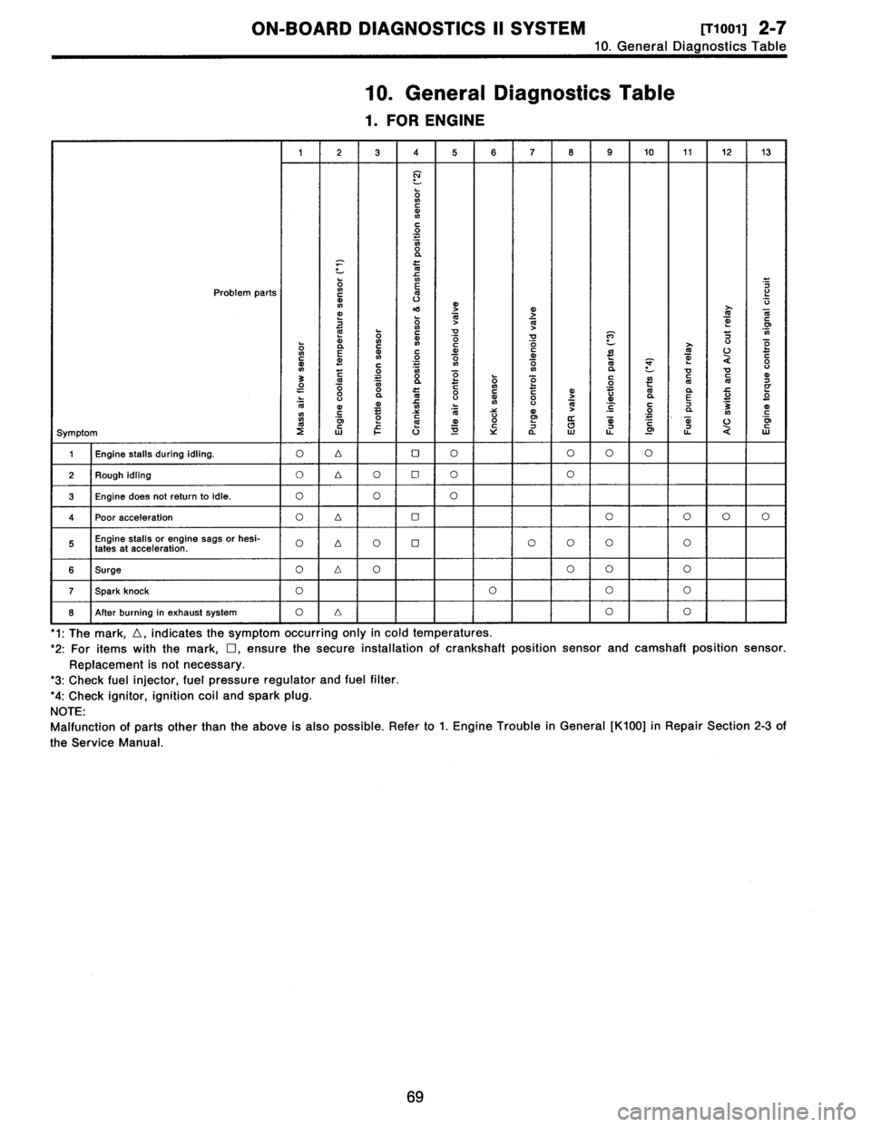
1
.
FOR
ENGINE
1
23
4
5678
9
10
11
1213
N
ONCdN
C
O
O
a
x
m
Problem
parts
`o
m
v
mj
4'S
O
1>j
T
N
dm
G
~
ON
41
m
~
!d
V
P]
7
0
E
m
~n
N
~o
C
o
O
d
~
~
U
O
c
m~
C
.
.
.
V1
ON
aVa
U
3
C~
0
"
y
dO1OyOQ
~
"O
CN
d7
O
"
0va
l0
0CdyGo
>
"
Vd
da
E
U
"
O
l0
ymC
~
O
NC
N
V
V
4)
N
~
'C
C
.2
7
a
3NmC
oi
mm
o
W
m
.
mU
o~
Symptom
2WFU~Ya
LL
.0
ti
QW
1
Engine
stalls
during
idling
.
O4OOOOO
2
Rough
idling
O
4O
Cl
OO
3
Engine
does
notreturnto
idle
.
O
OO
4Poor
acceleration
O4OOOOO
Engine
stalls
or
engine
sags
or
hesi-
O
D
OOOOOO
fates
at
acceleration
.
6
Surge
O4OOOO
T
Spark
knock
OOOO
8
After
burning
in
exhaust
system
O
Lr
I
O
I
'1
:
The
mark,
D,
indicates
the
symptom
occurring
only
in
cold
temperatures
.
'2
:
For
itemswiththe
mark,
D,ensure
the
secure
installationof
crankshaft
position
sensor
and
camshaft
position
sensor
.
Replacement
is
not
necessary
.
'3
:
Check
fuel
injector,
fuel
pressure
regulator
and
fuel
filter
.
'4
:
Check
ignitor,
ignition
coil
and
spark
plug
.
NOTE
:
Malfunction
of
partsother
than
the
above
is
also
possible
.
Refer
to
1
.
Engine
Trouble
in
General
[K100]
in
Repair
Section
2-3
of
the
Service
Manual
69
Page 83 of 2890
![SUBARU LEGACY 1996 Service Repair Manual 2-7
Rioo2]
ON-BOARD
DIAGNOSTICS
II
SYSTEM
10
.
General
Diagnostics
Table
41
Problem
parts
,-
CI,
~o
0
0-
N
N
N
L
yy
I
C
L
dCN
CN
f0
qp
ZNa
f0
j
¢m
r
NMLUr
7y
mr
~
.
`
.
"
UVUU
0
rJ
"
q0
N
d
N SUBARU LEGACY 1996 Service Repair Manual 2-7
Rioo2]
ON-BOARD
DIAGNOSTICS
II
SYSTEM
10
.
General
Diagnostics
Table
41
Problem
parts
,-
CI,
~o
0
0-
N
N
N
L
yy
I
C
L
dCN
CN
f0
qp
ZNa
f0
j
¢m
r
NMLUr
7y
mr
~
.
`
.
"
UVUU
0
rJ
"
q0
N
d
N](/manual-img/17/57433/w960_57433-82.png)
2-7
Rioo2]
ON-BOARD
DIAGNOSTICS
II
SYSTEM
10
.
General
Diagnostics
Table
41
Problem
parts
,-
CI,
~o
0
0-
N
N
N
L
yy
I
C
L
dCN
CN
f0
qp
ZNa
f0
j
¢m
r
NMLUr
7y
mr
'
~
.
`
.
"
UVUU
0
rJ
"
q0
N
d
N
dm
d
d
LY~O
.'~
O
LO
OO
O
~
d
OC
OC
~
OCOCOC
m
>
A
1
m~V>
d
O
~
OC
r
7
Uo
E
ym
y
m
~,
"
U
~
-
U
3
y
E
d
a
d
Y
i
N
m>
~
_m
>
E
_m
>
E
A>
E
a
E
d
m
om
y
0d
N
0m
N
d
0
N
d0
N
>
~
n
"
C
a
j
d
N
d
N
.
mo
N
CC
O
U
L
dU
L
d
d
m
G1
~
V~
0~a60U
0U
0V
0U
,
�
V-
F
C~
~
7
~
7
~L~L~t
C
O
41
dCWC~C~
WC~
T7
_v>>
~nv~~n
.
r-
xaaa
a
a
in
o
o
(D(ncn
voMPP
P
o
Symptom
1
2
345678910
11
12131415161718
,
19
2021
22
23
.24
25
1
26
1
27
28
29Engine
brake
is
noteffected
when
select
lever
isin
"3"
or
"2"range
.
Engine
brake
is
noteffected
when
select""
lever
isin
1
range
.
Shift
characteristics
areerroneous
.
OOOOOO
No
lock-up
occurs
.
OOOO
Vehicle
cannotbe
set
in
"D"
range
power
OO
mode
.
"D"
range
power
mode
cannotbe
released
.
OOO
Parking
brake
is
not
effected
.
OO
Shift
lever
cannot
be
moved
or
is
hard
to
"
"
move
from
P
range
.
Select
lever
is
hard
to
move
.
OOOO
Select
lever
is
too
light
to
move
(unreason-
OO
able
resistance)
.
ATF
spurts
out
.
Differential
oil
spurtsout
.
Differential
oil
level
changes
excessively
.
Odor
is
producedfrom
oil
supply
pipe
.
OO
Shock
occurs
when
selectlever
is
moved
""
"
"
OOO
O
OO
from
1
2
range
.
to
Slippage
occurs
when
selectlever
is
moved
"""
"
OOOOOO
from
1
to
2
range
.
Shock
occurs
when
selectlever
is
moved
"
""
"
OOOOOO
from
2
to
3
range
.
Slippage
occurs
when
selectlever
is
moved
""
O
OO
OOO
from
"2to
"3
range
.
Shock
occurs
when
select
lever
is
moved
"
"""
OOOOOO
from
4
range
.
3
to
Slippage
occurs
when
selectlever
is
moved
"
"
0OOOOO
to
"4from
"3
range
.
Shock
occurs
when
select
lever
is
moved
""
0OOO
O
from"3
to"2
range
.
Shock
occurs
when
selectlever
is
moved
"
UOOOO
from
"D
to
"1"
range
.
Shock
occurs
when
selectlever
is
moved
"
"
OO
O
OO
to"1
from"2
range
.
Shock
occurs
when
accelerator
pedal
is
O
OOO
O
released
at
medium
speeds
.
Vibration
occurs
during
straight-forward
OO
operation
.
Select
leveeslips
out
ofposition
during
acceleration
or
while
driving
onrough
ter-
OOO
U
rain
.
Vibration
occurs
during
turns
(tight
corner
"
OOOOOOOOO
"braking
phenomenon)
.
Front
wheel
slippage
occursduring
standing
OOOOOOOOOOO
starts
.
Vehicle
is
not
set
in
FWD
mode
.
O
O
vOO
1
23456i
7
8910
11T
21314
x
15
1
~
i
1819
~20
~
I
22226
272829
72