Page 322 of 2890
 Bleed air from hydraulic lash adjuster as described
below:
(1) While dipping hydraulic lash adjuster in engine oil,
as shown in Figure, push check ball in usinga2mm
(0.08 in) diameter round")
G2M0131
3) Bleed air from hydraulic lash adjuster as described
below:
(1) While dipping hydraulic lash adjuster in engine oil,
as shown in Figure, push check ball in usinga2mm
(0.08 in) diameter round bar.
(2) With check ball pushed in, manually move plunger
up and down at one second intervals until air bubbles
disappear.
(3) After air bubbles disappear, remove round bar and
quickly push plunger in to ensure it is locked. If plunger
does not lock properly, replace hydraulic lash adjuster.
CAUTION:
Leave hydraulic lash adjuster (after air is bled) in
engine oil until it is ready for installation.
G2M0200
4) Using ST;
(1) Insert lash adjuster into ST, and fill ST with engine
oil. Usinga2mm(0.08 in) diameter rod, push check
ball in.
ST 499597000 OIL SEAL GUIDE
(2) With check ball pushed in, push plunger at an inter-
val of one second.
(3) Move plunger up and down until air bubbles are no
longer emitted from lash adjuster.
NOTE:
Hold hydraulic lash adjusters vertically during air bleeding.
5) Remove the rod. Push plunger to ensure that air is
completely bled out.
CAUTION:
If plunger does not properly lock (when pushed),
replace lash adjuster with a new one.
13
2-3SERVICE PROCEDURE
2. Hydraulic Lash Adjuster
Page 338 of 2890
G2M0131
C: INSPECTION
1. HYDRAULIC LASH ADJUSTER
1) Bleed air from hydraulic lash adjuster as described
below:
(1) While dipping hydraulic lash adjuster in engine oil,
as shown in Figure, push check ball in usinga2mm
(0.08 in) diameter round bar.
(2) With check ball pushed in, manually move plunger
up and down at one second intervals until air bubbles
disappear.
(3) After air bubbles disappear, remove round bar and
quickly push plunger in to ensure it is locked. If plunger
does not lock properly, replace hydraulic lash adjuster.
CAUTION:
Leave hydraulic lash adjuster (after air is bled) in
engine oil until it is ready for installation.
2) Replace hydraulic lash adjuster with a new one if valve
contact surface is scratched.
29
2-3SERVICE PROCEDURE
4. Valve Rocker Assembly
Page 567 of 2890
G2M0358
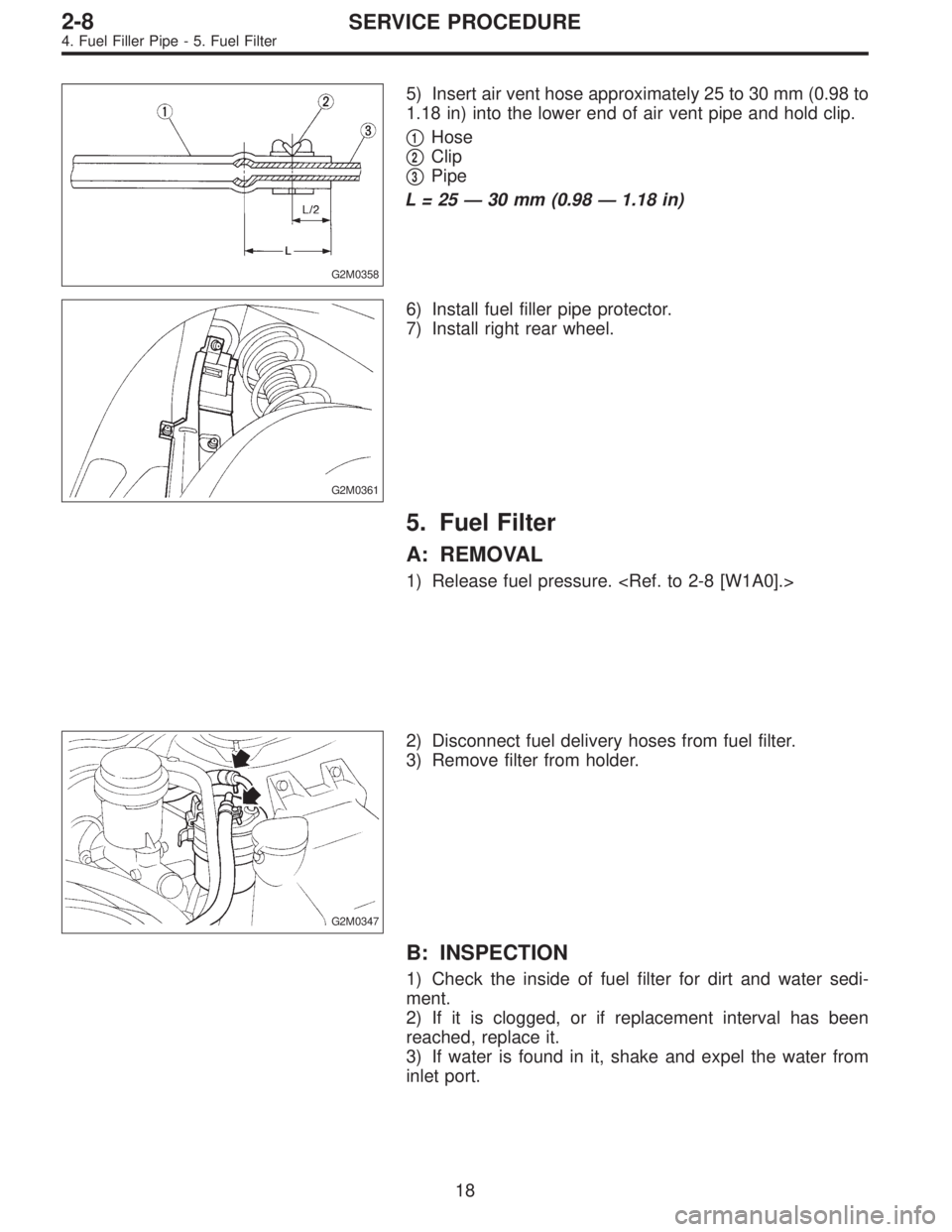
5) Insert air vent hose approximately 25 to 30 mm (0.98 to
1.18 in) into the lower end of air vent pipe and hold clip.
�
1Hose
�
2Clip
�
3Pipe
L=25—30 mm (0.98—1.18 in)
G2M0361
6) Install fuel filler pipe protector.
7) Install right rear wheel.
5. Fuel Filter
A: REMOVAL
1) Release fuel pressure.
G2M0347
2) Disconnect fuel delivery hoses from fuel filter.
3) Remove filter from holder.
B: INSPECTION
1) Check the inside of fuel filter for dirt and water sedi-
ment.
2) If it is clogged, or if replacement interval has been
reached, replace it.
3) If water is found in it, shake and expel the water from
inlet port.
18
2-8SERVICE PROCEDURE
4. Fuel Filler Pipe - 5. Fuel Filter
Page 677 of 2890
G2M0358
5) Insert air vent hose approximately 25 to 30 mm (0.98 to
1.18 in) into the lower end of air vent pipe and hold clip.
�
1Hose
�
2Clip
�
3Pipe
L=25—30 mm (0.98—1.18 in)
G2M0361
6) Install fuel filler pipe protector.
7) Install right rear wheel.
5. Fuel Filter
A: REMOVAL
1) Release fuel pressure.
G2M0347
2) Disconnect fuel delivery hoses from fuel filter.
3) Remove filter from holder.
B: INSPECTION
1) Check the inside of fuel filter for dirt and water sedi-
ment.
2) If it is clogged, or if replacement interval has been
reached, replace it.
3) If water is found in it, shake and expel the water from
inlet port.
18
2-8SERVICE PROCEDURE
4. Fuel Filler Pipe - 5. Fuel Filter
Page 678 of 2890
G2M0358
5) Insert air vent hose approximately 25 to 30 mm (0.98 to
1.18 in) into the lower end of air vent pipe and hold clip.
�
1Hose
�
2Clip
�
3Pipe
L=25—30 mm (0.98—1.18 in)
G2M0361
6) Install fuel filler pipe protector.
7) Install right rear wheel.
5. Fuel Filter
A: REMOVAL
1) Release fuel pressure.
G2M0347
2) Disconnect fuel delivery hoses from fuel filter.
3) Remove filter from holder.
B: INSPECTION
1) Check the inside of fuel filter for dirt and water sedi-
ment.
2) If it is clogged, or if replacement interval has been
reached, replace it.
3) If water is found in it, shake and expel the water from
inlet port.
18
2-8SERVICE PROCEDURE
4. Fuel Filler Pipe - 5. Fuel Filter
Page 866 of 2890

B: TIME LAG TEST
1. GENERAL
If the shift lever is shifted while the engine is idling, there
will be a certain time elapse or lag before the shock can be
felt. This is used for checking the condition of the forward
clutch, reverse clutch, low & reverse brake, forward one-
way clutch and low one-way clutch.
CAUTION:
�Perform the test at normal operation fluid tempera-
ture 60 to 80°C (140 to 176°F).
�Be sure to allow a one minute interval between tests.
�Make three measurements and take the average
value.
2. TEST METHODS
1) Fully apply the parking brake.
2) Start the engine.
Check idling speed (A/C OFF).
“N”range: 800±100 rpm
3) Shift the shift lever from“N”to“D”range.
Using a stop watch, measure the time it takes from shift-
ing the lever until the shock is felt.
Time lag: Less than 1.2 seconds
4) In same manner, measure the time lag for“N”,“R”.
Time lag: Less than 1.5 seconds
3. EVALUATION
1) If“N”,“D”time lag is longer than specified:
�Line pressure too low
�Forward clutch worn
�Low one-way clutch not operating properly
2) If“N”,“R”time lag is longer than specified:
�Line pressure too low
�Reverse clutch worn
�Low & reverse brake worn
�Forward one-way clutch not operating properly
40
3-2SERVICE PROCEDURE
3. Performance Test
Page 1269 of 2890

A: GENERAL RULES FOR EFFECTIVE
BLEEDING
1) Start with the brakes (wheels) connecting to the sec-
ondary chamber of the master cylinder.
2) The time interval betwee")
11. Air Bleeding (Without TCS model)
A: GENERAL RULES FOR EFFECTIVE
BLEEDING
1) Start with the brakes (wheels) connecting to the sec-
ondary chamber of the master cylinder.
2) The time interval between two brake pedal operations
(from the time when the pedal is released to the time when
it is depressed another time) shall be approximately 3 sec-
onds.
3) The air bleeder on each brake shall be released for 1
to 2 seconds.
B: BLEEDING PROCEDURE
CAUTION:
�The FMVSS No. 116, fresh DOT3 or 4 brake fluid
must be used.
�Cover bleeder with waste cloth, when loosening it,
to prevent brake fluid from being splashed over sur-
rounding parts.
�Avoid mixing different brands of brake fluid to pre-
vent degrading the quality of the fluid.
�Be careful not to allow dirt or dust to get into the
reservoir tank.
NOTE:
�During bleeding operation, keep the brake reserve tank
filled with brake fluid to eliminate entry of air.
�Brake pedal operating must be very slow.
�For convenience and safety, it is advisable to have two
man working.
G4M0434
G4M0435
1) Make sure that there is no leak from joints and connec-
tions of the brake system.
2) Fit one end of vinyl tube into the air bleeder and put the
other end into a brake fluid container.
3) Slowly depress the brake pedal and keep it depressed.
Then, open the air bleeder to discharge air together with
the fluid.
Release air bleeder for 1 to 2 seconds.
Next, with the bleeder closed, slowly release the brake
pedal.
Repeat these steps until there are no more air bubbles in
the vinyl tube.
Allow 3 to 4 seconds between two brake pedal operations.
CAUTION:
Cover bleeder with waste cloth, when loosening it, to
prevent brake fluid from being splashed over sur-
rounding parts.
NOTE:
Brake pedal operating must be very slow.
4) Tighten air bleeder securely when no air bubbles are
visible.
62
4-4SERVICE PROCEDURE
11. Air Bleeding (Without TCS model)
Page 1295 of 2890

A: RULES FOR EFFECTIVE BLEEDING
1) Pressure is not applied to suction pipe by depressing
brake pedal. When any of the following are performed,
bleed air from suction")
19. Air Bleeding (With TCS model)
A: RULES FOR EFFECTIVE BLEEDING
1) Pressure is not applied to suction pipe by depressing
brake pedal. When any of the following are performed,
bleed air from suction pipe by air bleeding control opera-
tion.
NOTE:
For TCS vehicle, suction pipe is installed between master
cylinder and hydraulic unit to allow flow of brake fluid
between them during ABS and TCS operation.
(1) When brake pipe is disconnected from master cyl-
inder.
(2) When brake pipe between hydraulic unit and mas-
ter cylinder is disconnected.
(3) When fluid is emptied from reservoir tank.
2) The time interval between two brake pedal operations
(from the time when the pedal is released to the time when
it is depressed another time) shall be approximately 3 sec-
onds.
3) The air bleeder on each brake shall be released for 1
to 2 seconds.
B: BLEEDING PROCEDURE WITH AIR
BLEEDING CONTROL
1. BLEEDING PROCEDURE
CAUTION:
�The FMVSS No. 116, fresh DOT3 or 4 brake fluid
must be used.
�Cover bleeder with waste cloth, when loosening it,
to prevent brake fluid from being splashed over sur-
rounding parts.
�Avoid mixing different brands of brake fluid to pre-
vent degrading the quality of the fluid.
�Be careful not to allow dirt or dust to get into the
reservoir tank.
�During bleeding operation, keep the brake reserve
tank filled with brake fluid to eliminate entry of air.
NOTE:
�Brake pedal operating must be very slow.
�For convenience and safety, it is advisable to have two
man working.
G4M0434
1) Start air bleeding control operation.
[W19C0] or [W19D0].>
2) Make sure that there is no leak from joints and connec-
tions of the brake system.
3) Bleed air through front RH caliper by operating brake
pedal.
(1) Fit one end of vinyl tube into the air bleeder and put
the other end into a brake fluid container.
86
4-4SERVICE PROCEDURE
19. Air Bleeding (With TCS model)
 Bleed air from hydraulic lash adjuster as described
below:
(1) While dipping hydraulic lash adjuster in engine oil,
as shown in Figure, push check b")