Page 2 of 2890
SPECIFICATIONS
[s21o1
1-1
2
.
Station
Wagon
10
.
WEIGHT
Model
AWD
POST
4AT
Curb
weight
(C
.W
.)
Front
kg
(1b)
748
(1,650)
Rear
kg
(1b)
619
(1,365)
Total
kg
(1b)
1,367
(3,015)
Gross
vehicle
weight
Front
kg
(1b)
936
(2,065)
(G
.V
.W
.)
Rear
kg
(1b)
9S9
(2,180)
Total
kg
(1b)
1,925
(4,245)
NOTE
:
Includes
the
weights
of
power
window,
power
door
lock
and
air
conditioning
in
the
curb
weight
.
Page 3 of 2890
1-3
[0301]
GENERAL
INFORMATION
3
.
Vehicle
Identification
Numbers
(V
.I
.N)
3
.
Vehicle
Identification
Numbers
(V
.I
.N)
1
.
APPLICABLE
V
.I
.N
.
IN
THIS
MANUAL
Station
2200
cc
AWD
~
4AT
T
4
TS
3
1
B
I
KT
I
9
I
5X
I
T
I
8
I
T
2
00
1
and
after
Wagon
engine
POST
2
.
THE
MEANINGOF
V
.I
.N
.
Marker
identifier
l
Stop-
mark
4
S
3
Sequential
number
302001
and
after
:
Station
Wagon
Plant
of
manufacture
and
transmission
type
Plant
of
manufacture
Transmissiontype
SIA
POST
8
(Full-time
AWD
4AT)
Model
year
T
1996
Check
digit
Weight
class
and
restraint
type
Passenger
car
5
:
Withoutpassive
restraint,
with
Dual
SRS
airbag
Model
9
:
POST
Engine
type
4
:
2
.2
liter
engine
Body
type
K
:
Station
Wagon
Line
B
:
SUBARU
B
line
Plant
of
manufacture
Plant
of
manufacture
Type
of
vehicle
SIA
I
4S3
~
Passenger
car
I
Vehicle
attributes
Check
digit
Vehicle
identification
BK
495
X
T
83
0200
1
[
TT
I
T
T
ITT
Z
Stop
mark
2
Page 731 of 2890
G2M0294
15) Separate torque converter from drive plate. (AT model)
(1) Lower the vehicle.
(2) Remove service hole plug.
(3) Remove bolts which hold torque converter to drive
plate.
(4) Remove other bolts while rotating the engine using
ST.
ST 499977000 CRANK PULLEY WRENCH
G2M0295
16) Remove pitching stopper.
B2M0336
17) Disconnect fuel delivery hose, return hose and evapo-
ration hose.
CAUTION:
�Disconnect hose with its end wrapped with cloth to
prevent fuel from splashing.
�Catch fuel from hose into container.
G2M0297
18) Support engine with a lifting device and wire ropes.
G2M0298
19) Support transmission with a garage jack.
CAUTION:
Before moving engine away from transmission, check
to be sure no work has been overlooked. Doing this is
very important in order to facilitate re-installation and
because transmission lowers under its own weight.
18
2-11SERVICE PROCEDURE
2. Engine
Page 802 of 2890
 Place the transmission with case left side facing
downward and put ST1 on bearing cup.
(2) Screw retainer assembly into left case from the bot-
tom with ST2. Fit ST3 on the transmission ma")
G3M0564
(1) Place the transmission with case left side facing
downward and put ST1 on bearing cup.
(2) Screw retainer assembly into left case from the bot-
tom with ST2. Fit ST3 on the transmission main shaft.
Shift gear into 4th or 5th and turn the shaft several
times. Screw in the retainer while turning ST3 until a
slight resistance is felt on ST2.
This is the contact point of hypoid gear and drive pin-
ion shaft. Repeat the above sequence several times to
ensure the contact point.
ST1 399780104 WEIGHT
ST2 499787000 WRENCH ASSY
ST3 499927100 HANDLE
B3M0340A
(3) Remove weight and screw in retainer without
O-ring on the upper side and stop at the point where
slight resistance is felt.
NOTE:
At this point, the backlash between the hypoid gear and
drive pinion shaft is zero.
ST 499787000 WRENCH ASSY
B3M0334A
(4) Fit lock plate�11. Loosen the retainer on the lower
side by 1-1/2 notches of lock plate and turn in the
retainer on the upper side by the same amount in order
to obtain the backlash.
NOTE:
The notch on the lock plate moves by 1/2 notch if the plate
is turned upside down.
(5) Turn in the retainer on the upper side additionally
by 1 notch in order to apply preload on taper roller
bearing.
(6) Tighten temporarily both the upper and lower lock
plates and mark both holder and lock plate for later
readjustment.
(7) Turn transmission main shaft several times while
tapping around retainer lightly with plastic hammer.
(8) Set ST1 and ST2. Insert the needle through trans-
mission oil drain plug hole so that the needle comes in
contact with the tooth surface at a right angle and check
the backlash.
46
3-1SERVICE PROCEDURE
4. Transmission Case
Page 989 of 2890
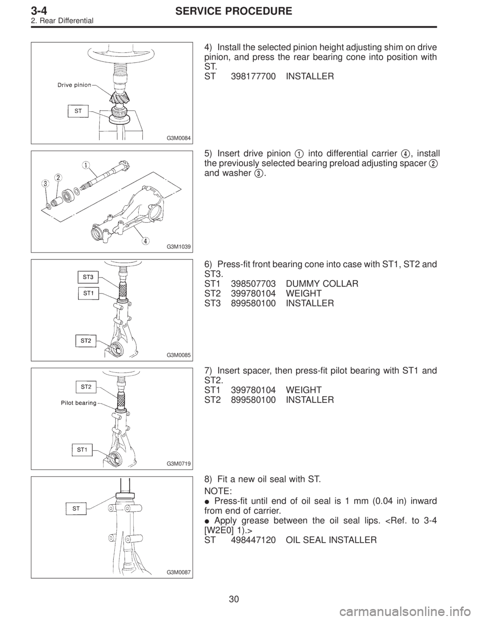
G3M0084
4) Install the selected pinion height adjusting shim on drive
pinion, and press the rear bearing cone into position with
ST.
ST 398177700 INSTALLER
G3M1039
5) Insert drive pinion�1into differential carrier�4, install
the previously selected bearing preload adjusting spacer�
2
and washer�3.
G3M0085
6) Press-fit front bearing cone into case with ST1, ST2 and
ST3.
ST1 398507703 DUMMY COLLAR
ST2 399780104 WEIGHT
ST3 899580100 INSTALLER
G3M0719
7) Insert spacer, then press-fit pilot bearing with ST1 and
ST2.
ST1 399780104 WEIGHT
ST2 899580100 INSTALLER
G3M0087
8) Fit a new oil seal with ST.
NOTE:
�Press-fit until end of oil seal is 1 mm (0.04 in) inward
from end of carrier.
�Apply grease between the oil seal lips.
[W2E0] 1).>
ST 498447120 OIL SEAL INSTALLER
30
3-4SERVICE PROCEDURE
2. Rear Differential
Page 990 of 2890
G3M0720
9) Press-fit companion flange with ST1 and ST2.
CAUTION:
Be careful not to damage bearing.
ST1 899874100 INSTALLER
ST2 399780104 WEIGHT
G3M1052
10) Install self-locking nut. Then tighten it with ST.
ST 498427200 FLANGE WRENCH
Tightening torque:
181±15 N⋅m (18.5±1.5 kg-m, 134±11 ft-lb)
G3M0069
11) Install crown gear on differential case.
Tightening Torque:
103±10 N⋅m (10.5±1.0 kg-m, 76±7 ft-lb)
NOTE:
Tighten diagonally while tapping the bolt heads.
G3M1041
12) Before installing side bearing, measure the bearing
width by using a dial gauge, ST1 and ST2.
Standard bearing width:
20.00 mm (0.7874 in)
NOTE:
Set the dial gauge needle to zero, using a standard bear-
ing or block of specified height in advance.
ST1 398227700 WEIGHT
ST2 398237700 GAUGE
G3M0091
13) Press side bearing cone onto differential case with
ST1.
ST1 398487700 DRIFT
31
3-4SERVICE PROCEDURE
2. Rear Differential
Page 1009 of 2890
1. WHEEL ARCH HEIGHT
1) Adjust tire pressure to specifications.
2) Set vehicle under“curb weight”conditions. (Empty lug-
gage compartment, install spare tire, jack, service tools,
and top up fuel tank.)
3) Set steering wheel in a wheel-forward position.
4) Suspend thread from wheel arch (point“A”in figure
below) to determine a point directly above center of
spindle.
5) Measure distance between measuring point and center
of spindle.
B4M0566A
VehiclesSpecified wheel arch height mm (in)
Front Rear
SedanFWD 385
+12
�24(15.16+0.47
�0.94) 369+12
�24(14.53+0.47
�0.94)
AWD 385
+12
�24(15.16+0.47
�0.94) 369+12
�24(14.53+0.47
�0.94)
WagonFWD 385
+12
�24(15.16+0.47
�0.94) 379+12
�24(14.92+0.47
�0.94)
AWD 385
+12
�24(15.16+0.47
�0.94) 379+12
�24(14.92+0.47
�0.94)
OUTBACK AWD 420
+12
�24(16.54+0.47
�0.94) 419+12
�24(16.50+0.47
�0.94)
8
4-1SERVICE PROCEDURE
1. On-car Services
Page 1020 of 2890
G4M0497
4) Connect stabilizer link to transverse link, and tempo-
rarily tighten bolts.
CAUTION:
Discard loosened self-locking nut and replace with a
new one.
5) Tighten the following points in the order shown below
when wheels are in full contact with the ground and vehicle
is at curb weight condition.
(1) Transverse link and stabilizer link
Tightening torque:
29±5 N⋅m (3.0±0.5 kg-m, 21.7±3.6 ft-lb)
(2) Transverse link and crossmember
Tightening torque:
98±15 N⋅m (10.0±1.5 kg-m, 72±11 ft-lb)
G4M0928
(3) Transverse link rear bushing and body
Tightening torque:
245±49 N⋅m (25±5 kg-m, 181±36 ft-lb)
NOTE:
�Move rear bushing back and forth until transverse link-
to-rear bushing clearance is established (as indicated in
figure.) before tightening.
�Check wheel alignment and adjust if necessary.
19
4-1SERVICE PROCEDURE
2. Front Transverse Link

Front
kg
(1b)
748
(1,650)
Rear
kg
(1b)
619
(1,365)
Total
kg
(1b)
1,367
(3,015)
Gross
vehicle
we")
![SUBARU LEGACY 1996 Service Repair Manual 1-3
[0301]
GENERAL
INFORMATION
3
.
Vehicle
Identification
Numbers
(V
.I
.N)
3
.
Vehicle
Identification
Numbers
(V
.I
.N)
1
.
APPLICABLE
V
.I
.N
.
IN
THIS
MANUAL
Station
2200
cc
AWD
~
4AT
T
4
TS
3](/manual-img/17/57433/w960_57433-2.png "SUBARU LEGACY 1996 Service Repair Manual 1-3
[0301]
GENERAL
INFORMATION
3
.
Vehicle
Identification
Numbers
(V
.I
.N)
3
.
Vehicle
Identification
Numbers
(V
.I
.N)
1
.
APPLICABLE
V
.I
.N
.
IN
THIS
MANUAL
Station
2200
cc
AWD
~
4AT
T
4
TS
3")
 Separate torque converter from drive plate. (AT model)
(1) Lower the vehicle.
(2) Remove service hole plug.
(3) Remove bolts which hold torque converter to drive
plate.
(4) Remove other bo")
 Press-fit companion flange with ST1 and ST2.
CAUTION:
Be careful not to damage bearing.
ST1 899874100 INSTALLER
ST2 399780104 WEIGHT
G3M1052
10) Install self-locking nut. Then tighten it wi")
 Adjust tire pressure to specifications.
2) Set vehicle under“curb weight”conditions. (Empty lug-
gage compartment, install spare tire, jack, service tools,
and top up fuel")
 Connect stabilizer link to transverse link, and tempo-
rarily tighten bolts.
CAUTION:
Discard loosened self-locking nut and replace with a
new one.
5) Tighten the following points in the or")