Page 35 of 2890
2-7
[T3C7]
ON-BOARD
DIAGNOSTICS
II
SYSTEM
3
.
Diagnosis
System
82M0476
7
.
FUNCTION
MODE
:
F00
-
ROM
ID
NUMBER
(YEAR)
-
CONDITION
:
Ignition
switch
"ON"
SPECIFIED
DATA
:
Presentation
display
Probable
cause
(Item
outside"specifieddata")
1
.
Error
1
2
.
Error2
vB
(F01)
12
.4
V
B2M0270
Probable
cause
(Item
outside
"specified
data")
1
.
Battery
1
2
.
Charging
system
1
3
.
Power
supply
line
Check
for
loose
or
disconnected
connector,
and
discontinued
circuit,
etc
.
Check
for
poor
contact
of
cartridge,
or
different
type
cartridge
.
8
.
FUNCTION
MODE
:
F01
-
BATTERY
VOLTAGE
(VB)
-
CONDITION
:
(1)
Ignition
switch
"ON"
(2)
Idling
after
warm-up
SPECIFIED
DATA
:
(1)
111
V
(2)
13
f
1
V
Check
battery
voltage
and
electrolyte's
specific
gravity
.
"
Check
regulating
voltage
.
(On
no-load)
Check
alternator
.
o
Check
main
relay
.
<
Ref
.
to
[T9C0]
.*4>
*
Check
harness
connector
of
ECM
power
supply
line
.
.
to
[T9C0]
.*4>
20
Page 481 of 2890
Lower level
3.5�(3.7 US qt, 3.1 Imp qt)
G2M0088
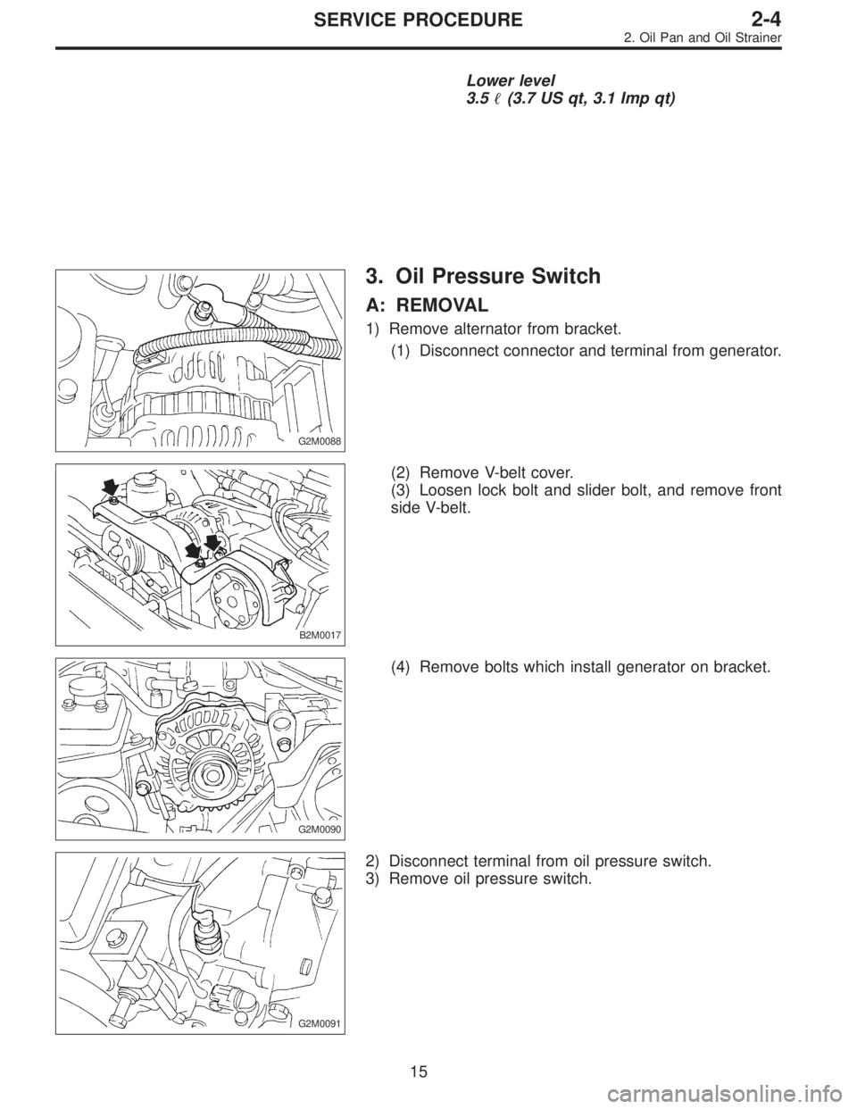
3. Oil Pressure Switch
A: REMOVAL
1) Remove alternator from bracket.
(1) Disconnect connector and terminal from generator.
B2M0017
(2) Remove V-belt cover.
(3) Loosen lock bolt and slider bolt, and remove front
side V-belt.
G2M0090
(4) Remove bolts which install generator on bracket.
G2M0091
2) Disconnect terminal from oil pressure switch.
3) Remove oil pressure switch.
15
2-4SERVICE PROCEDURE
2. Oil Pan and Oil Strainer
Page 482 of 2890
Lower level
3.5�(3.7 US qt, 3.1 Imp qt)
G2M0088
3. Oil Pressure Switch
A: REMOVAL
1) Remove alternator from bracket.
(1) Disconnect connector and terminal from generator.
B2M0017
(2) Remove V-belt cover.
(3) Loosen lock bolt and slider bolt, and remove front
side V-belt.
G2M0090
(4) Remove bolts which install generator on bracket.
G2M0091
2) Disconnect terminal from oil pressure switch.
3) Remove oil pressure switch.
15
2-4SERVICE PROCEDURE
2. Oil Pan and Oil Strainer
Page 725 of 2890
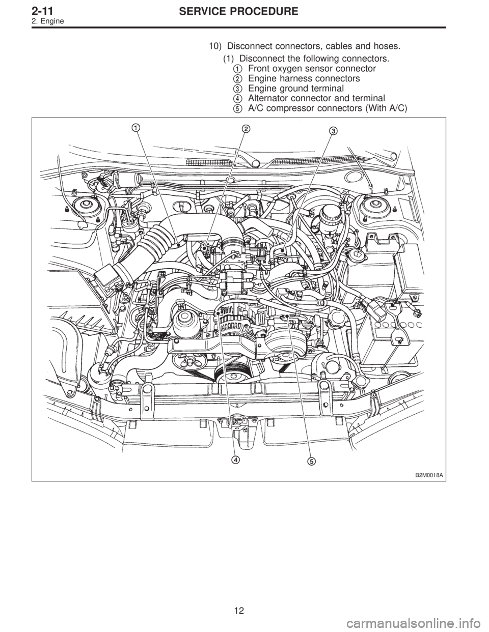
10) Disconnect connectors, cables and hoses.
(1) Disconnect the following connectors.
�
1Front oxygen sensor connector
�
2Engine harness connectors
�
3Engine ground terminal
�
4Alternator connector and terminal
�
5A/C compressor connectors (With A/C)
B2M0018A
12
2-11SERVICE PROCEDURE
2. Engine
Page 737 of 2890
11) Install front exhaust pipe and center exhaust pipe.
12) Connect hoses, connectors and cables.
(1) Connect the following hoses.
�Fuel delivery hose, return hose and evaporation
hose
�Heater inlet and outlet hoses
�Brake booster vacuum hose
(2) Connect the following connectors.
�Engine ground terminal
�Engine harness connectors
�Front oxygen sensor connector
�Rear oxygen sensor connector
�Alternator connector and terminal
�A/C compressor connectors (With A/C)
(3) Connect the following cables.
�Accelerator cable
�Cruise control cables (With cruise control)
�Clutch cable
�Clutch release spring
CAUTION:
After connecting each cable, adjust them.
G2M0271
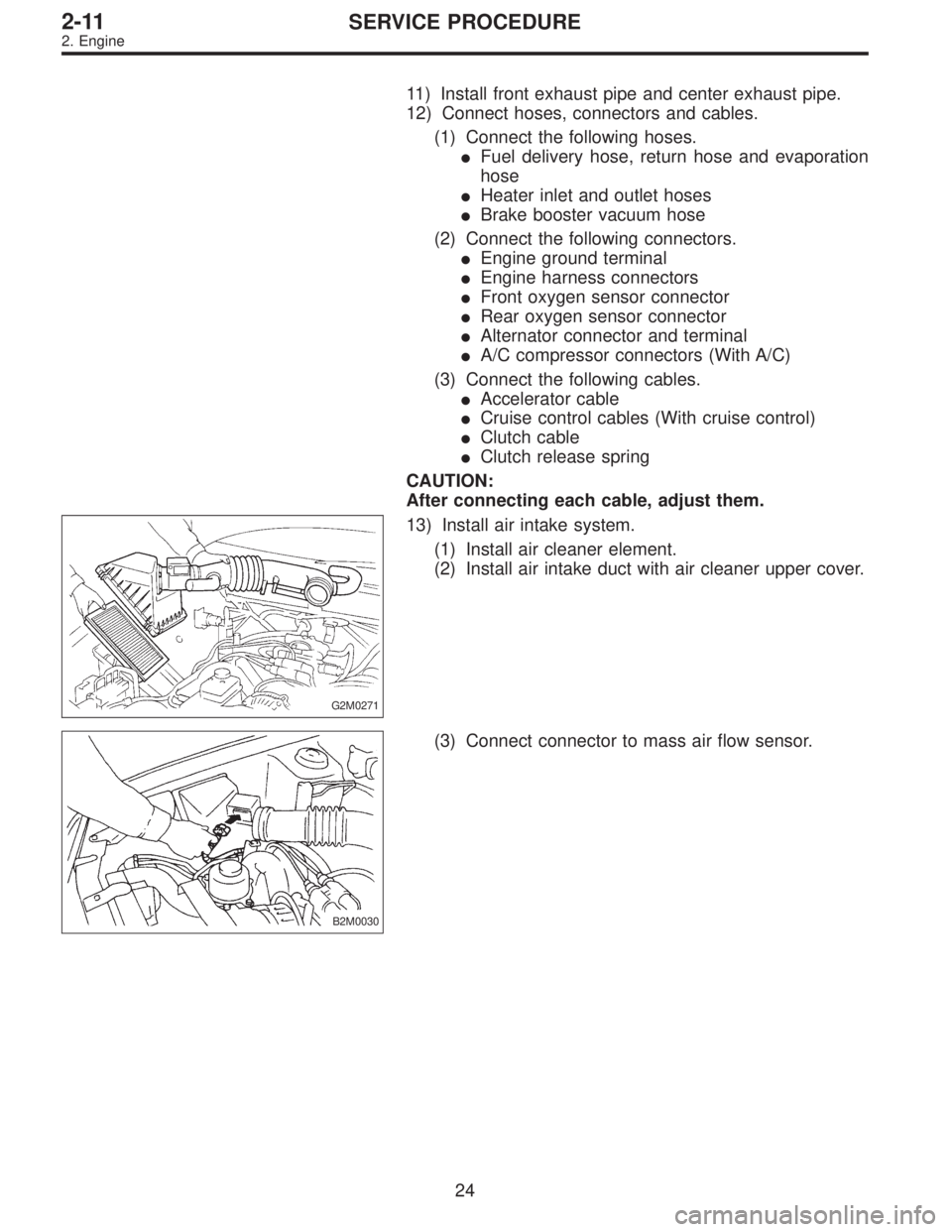
13) Install air intake system.
(1) Install air cleaner element.
(2) Install air intake duct with air cleaner upper cover.
B2M0030
(3) Connect connector to mass air flow sensor.
24
2-11SERVICE PROCEDURE
2. Engine
Page 1178 of 2890

A: REMOVAL
1) Remove ground cable from battery.
2) Drain the working fluid about 0.35�(0.4 US qt, 0.3 Imp
qt) from oil tank.
3) Remove pulley belt cover bra")
B4M0558
9. Oil Pump (Power Steering System)
A: REMOVAL
1) Remove ground cable from battery.
2) Drain the working fluid about 0.35�(0.4 US qt, 0.3 Imp
qt) from oil tank.
3) Remove pulley belt cover bracket.
B4M0559A
4) Loosen oil pump pulley nut, then remove bolts which
secure alternator.
5) Loosen pulley belt(s).
6) Remove the nut and detach oil pump pulley.
B4M0556A
7) Remove bolt A. Disconnect pipe C from oil pump. Dis-
connect pipe D from oil tank.
CAUTION:
�Do not allow fluid from the hose end to come into
contact with pulley belt.
�To prevent foreign matter from entering the hose
and pipe, cover the open ends of them with a clean
cloth.
�Except when only oil tank needs to be inspected,
detach oil tank and oil pump as a unit. Then separate
one from the other on a work bench to prevent oil from
spilling on any part of the engine.
B4M0560
8) Remove three bolts from the front side of oil pump and
detach the pump.
9) Remove three bolts from the lower side of bracket and
detach the bracket.
CAUTION:
The bracket does not need to be removed unless it is
damaged.
71
4-3SERVICE PROCEDURE
9. Oil Pump (Power Steering System)
Page 1380 of 2890
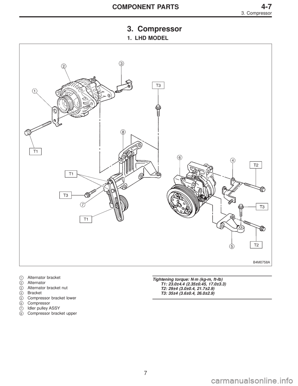
3. Compressor
1. LHD MODEL
B4M0758A
�1Alternator bracket
�
2Alternator
�
3Alternator bracket nut
�
4Bracket
�
5Compressor bracket lower
�
6Compressor
�
7Idler pulley ASSY
�
8Compressor bracket upper
Tightening torque: N⋅m (kg-m, ft-lb)
T1: 23.0±4.4 (2.35±0.45, 17.0±3.3)
T2: 29±4 (3.0±0.4, 21.7±2.9)
T3: 35±4 (3.6±0.4, 26.0±2.9)
7
4-7COMPONENT PARTS
3. Compressor
Page 1381 of 2890
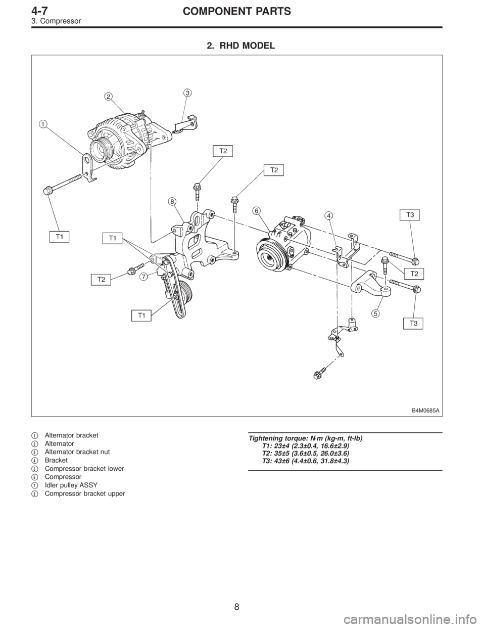
2. RHD MODEL
B4M0685A
�1Alternator bracket
�
2Alternator
�
3Alternator bracket nut
�
4Bracket
�
5Compressor bracket lower
�
6Compressor
�
7Idler pulley ASSY
�
8Compressor bracket upper
Tightening torque: N⋅m (kg-m, ft-lb)
T1: 23±4 (2.3±0.4, 16.6±2.9)
T2: 35±5 (3.6±0.5, 26.0±3.6)
T3: 43±6 (4.4±0.6, 31.8±4.3)
8
4-7COMPONENT PARTS
3. Compressor
![SUBARU LEGACY 1996 Service Repair Manual
2-7
[T3C7]
ON-BOARD
DIAGNOSTICS
II
SYSTEM
3
.
Diagnosis
System
82M0476
7
.
FUNCTION
MODE
:
F00
-
ROM
ID
NUMBER
(YEAR)
-
CONDITION
:
Ignition
switch
"ON"
SPECIFIED
DATA
:
Presentation
display](/manual-img/17/57433/w960_57433-34.png "SUBARU LEGACY 1996 Service Repair Manual
2-7
[T3C7]
ON-BOARD
DIAGNOSTICS
II
SYSTEM
3
.
Diagnosis
System
82M0476
7
.
FUNCTION
MODE
:
F00
-
ROM
ID
NUMBER
(YEAR)
-
CONDITION
:
Ignition
switch
\"ON\"
SPECIFIED
DATA
:
Presentation
display")