Page 86 of 2890
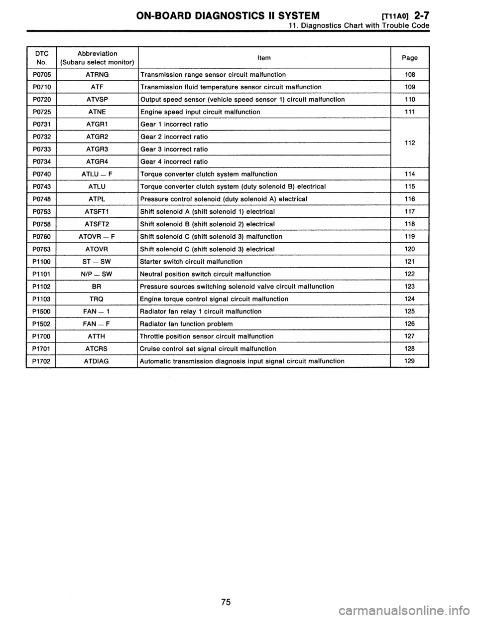
ON-BOARD
DIAGNOSTICS
11
SYSTEM
[T11aoj
2-7
11
.
Diagnostics
Chart
with
Trouble
Code
DTC
No
.
Abbreviation
(Subaru
select
monitor)
Item
Page
P0705
ATRNG
Transmissionrange
sensor
circuit
malfunction
108
P0710
ATF
Transmission
fluid
temperature
sensor
circuit
malfunction
109
P0720
ATVSP
Output
speed
sensor
(vehicle
speed
sensor
1)
circuit
malfunction
110
P0725
ATNE
Engine
speed
input
circuit
malfunction
111
P0731
ATGR1
Gear
1
incorrect
ratio
P0732
ATGR2
Gear
2
incorrect
ratio
1
2
P0733
ATGR3
Gear
3
incorrect
ratio
1
P0734
ATGR4
Gear
4
incorrect
ratio
P0740
ATLU
-
F
Torque
converter
clutch
system
malfunction
114
P0743
ATLU
Torque
converter
clutch
system
(duty
solenoid
B)
electrical
115
P0748
ATPL
Pressure
control
solenoid
(duty
solenoid
A)
electrical
116
P0753
ATSFTi
Shift
solenoid
A
(shift
solenoid
1)
electrical
117
P0758
ATSFT2
Shift
solenoid
B
(shift
solenoid
2)
electrical
118
P0760
ATOVR
-
F
Shift
solenoid
C
(shift
solenoid
3)
malfunction
119
P0763
ATOVR
Shift
solenoid
C
(shift
solenoid
3)
electrical
120
P1100
ST
-
SW
Starter
switch
circuit
malfunction
121
P1101
N/P
-
SW
Neutral
position
switch
circuit
malfunction
122
P1102
BR
Pressure
sources
switching
solenoid
valve
circuit
malfunction
123
P1103
TRQ
Engine
torque
control
signal
circuit
malfunction
124
P1500
FAN
-
1
Radiator
fan
relay
1
circuit
malfunction
125
P1502
FAN
-
F
Radiator
fan
function
problem
126
P1700
ATTH
Throttle
position
sensor
circuit
malfunction
127
P1701
ATCRS
Cruise
control
set
signal
circuit
malfunction
128
P1702
ATDIAG
Automatic
transmission
diagnosis
inputsignal
circuit
malfunction
I
129
75
Page 125 of 2890
2-7
[T11AV0]
ON-BOARD
DIAGNOSTICS
11
SYSTEM
11
.
Diagnostics
Chart
with
Trouble
Code
AV
:
DTC
P0740
-
TORQUE
CONVERTER
CLUTCH
SYSTEM
MALFUNCTION
(ATLU
-
F)
-
WIRING
DIAGRAM
:
Automatic
transmission
Duty
ATF
Vehicle
solenoid
temperature
speed
B
sensor
sensorl
854
Brake
Throttle
b~
B55
1
Ii
t
positions
856
B11
T4
B53
TCM
Inhibitor
switch
N
00
0
a
t
~
3
1
B12
T3
Combination
meter
Speedometer
ECM
circuit
B84
e
:
B54
b
:
855
c
:
B56BI1B53812
O
123456
123456712345678910
81
1
234
5
67
8
9101112
1234
5678
910
11
12
13141516
3132
33
3435
363738394
0
4142
4344
6970
58596061626364L
111
9
1
10
1
11
1
12
1
13
1
14
1
15
11
6
789
101112
1
11
1
12
1
13
1
14
1
15
1
16
1
171819
20
1314
I
I6
1
2349
10
1112
8485
86
87888990
91
E3
1
0
-
4
1
95
96
12
B2M0587
NOTE
:
For
the
diagnostic
procedure
on
torque
converter
clutch
system
malfunction
(DTC
P0740),
referto
2-7
[T10AV0]*2
.
114
Page 126 of 2890
ON-BOARD
DIAGNOSTICS
II
SYSTEM
[r1iawo1
2-7
11
.
Diagnostics
Chart
with
Trouble
Code
AW
:
DTC
P0743
-
TORQUE
CONVERTER
CLUTCH
SYSTEM
(DUTY
SOLENOID
B)
ELECTRICAL
(ATLU)
-
WIRING
DIAGRAM
:
855
-
BII
T4
TCM
855
12345678
1911011121314t
16
B11
131421516
OBD0413
I
NOTE
:
For
the
diagnostic
procedure
on
torque
converter
clutch
system
electrical
(DTC
P0743),
refer
to
2-7
[T10AW0]*2
.
115
Page 179 of 2890
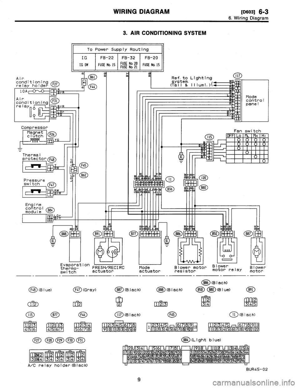
WIRING
DIAGRAM
[113so31
6-3
6
.
Wiring
Diagram
3
.
AIR
CONDITIONING
SYSTEM
Air
conditioningrelay
holder
F27
Compressor
Magnet
F24
clutch
Thermal
protector
F48
Pressure
switch
Q47
Engine
control
module
l
a
p
To
Power
Supply
Routing
IG
FB-22
FB-32
FB-20
IG
SW
FUSE
Na
15
FUSE
Na20FUSENa
21
FUSE
Na
15
M
11
Evaporation
thermo-
FRESH/RECIRC
switch
actuator
F48
(B
I
ue)
(j~)
(Gr
ay)
(M
FIT2-1
123
45
6
C1-
F2~
n
R3
[4151617
1
234
(~D(~D(~D
(~~D
(E)
j
F1W2-1
1
2
1
2
1
2
1
2-
-
-
MMMM
F3T
i
0
9
4
1
3
4
34
34
34
A/Crelay
holder(Black)
Mode
actuator
Ref
.
to
Lighting
Blower
motor
Blower
resistor
motor
relay
O
(B
I
ac
k)
Blower
motor
B87
(B
I
ac
k)
O
(B
I
ac
k)
B50880
(B
I
ue)
B91
1
12
1
2
123
34
345
i
ll
(B
I
ac
k)F45
1
l
(B
I
ac
k)
1
234S
I
6
1
7
1
12345
b789
125
6789(0
34
I1121314t516171819202122
1
9
1
10
1
11
1
12
1
13
1
14
1
15
1
t6
111121314t51617t81920~~
BB4
(L
t
ght
b
I
ue)
12U34
U
56
U
78
U
U
9l0
U
Ilt2
U
1314LJ1516
17
1
18
1
19
1
20
1
21
1
22
1
23
1
24
1
25
1
26
1
27
1
28
1
29
1
30
1
31323
3
34
35
3637
38
39
40
4142
43
44454647
1
48
1
49
~
0
1
51
1
52
1
53
1
54
~
5
1
56
1
57
1
M59
1
60
1
61
~
2
1
63
1
64
1
65
1
66
1
67
1
66
1
69
1
7'
7172
73
74
75
76777B7980
81
1
89
1
83
1
84
8
86878889
90
9192
93
94
996
BUR45-02
9
Page 192 of 2890
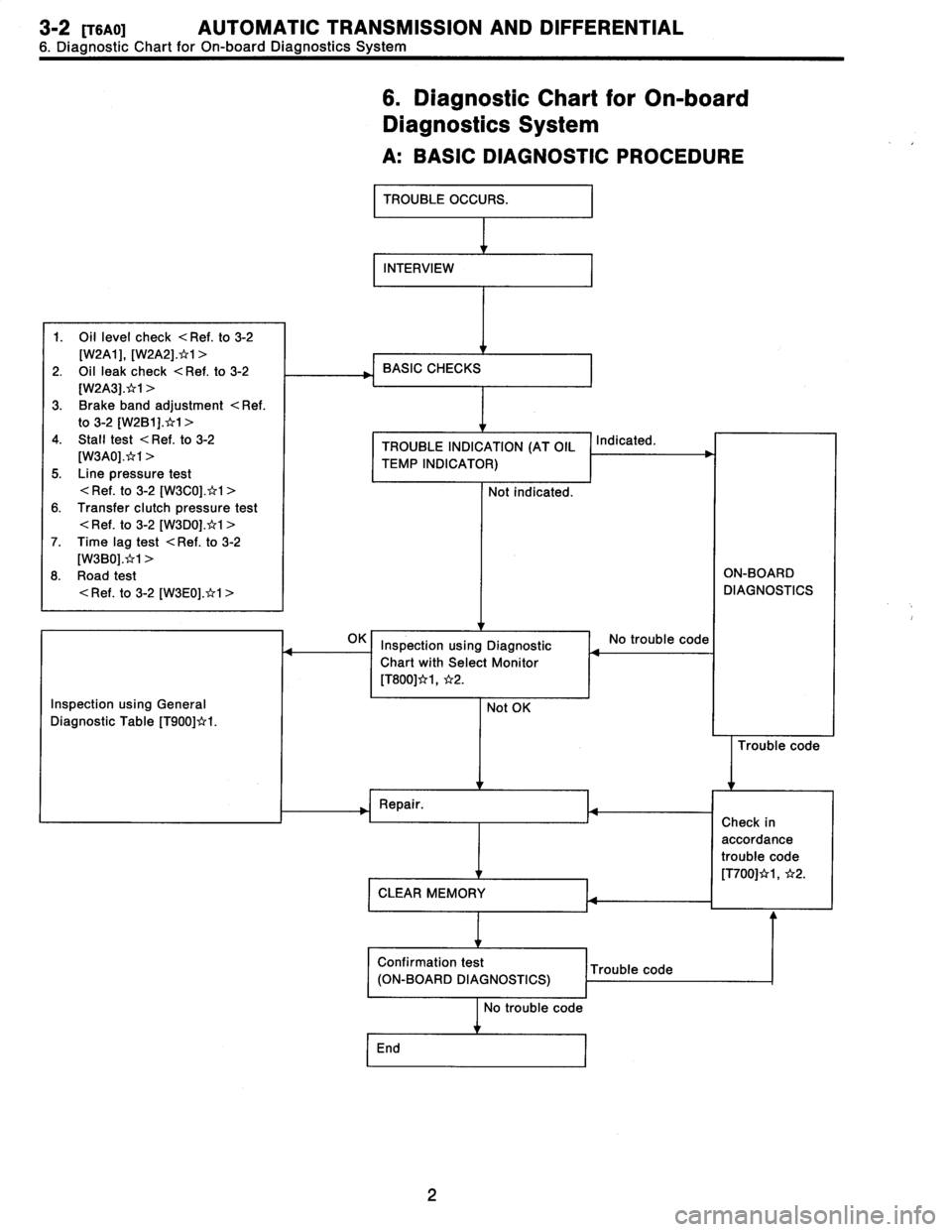
3-2
[TSAO1
AUTOMATIC
TRANSMISSION
AND
DIFFERENTIAL
6
.
Diagnostic
Chart
for
On-board
Diagnostics
System
6
.
Diagnostic
Chart
for
On-board
Diagnostics
System
A
:
BASICDIAGNOSTIC
PROCEDURE
TROUBLE
OCCURS
.
INTERVIEW
1
.
Oil
level
check
<
Ref
.
to
3-2
[W2A1],
[W2A2]
.*1
>
2
.
Oil
leak
check
<
Ref
.
to
3-2
[W2A3]
.x`r1
>
3
.
Brake
band
adjustment
<
Ref
.
to
3-2
[W2B1]
.t`r1
>
4
.
Stall
test
<
Ref
.
to
3-2
[W3A0]
.*1
>
5
.
Line
pressure
test
<
Ref
.
to
3-2
[W3C0]
.*1
>
6
.
Transfer
clutch
pressure
test
<
Ref
.
to
3-2
[W3D0]
.*1
>
7
.
Time
lag
test
<
Ref
.
to
3-2
[W3B0]
.*1
>
8
.
Road
test
<
Ref
.
to
3-2
[W3E0]
.*1
>
BASIC
CHECKS
TROUBLE
INDICATION
(AT
OIL
TEMP
INDICATOR)
Not
indicated
.
Indicated
.
ON-BOARD
DIAGNOSTICS
Inspection
using
General
Diagnostic
Table
[T900]*I
.
I
Inspection
using
Diagnostic
Chart
with
Select
Monitor
[T800]*1,
*2
.
Not
OK
No
trouble
code
Trouble
code
Repair
.
CLEAR
MEMORY
Confirmation
test
Trouble
code
(ON-BOARD
DIAGNOSTICS)
No
trouble
code
End
Check
in
accordance
trouble
code
[T700]*1,
*2
.
2
Page 212 of 2890
~
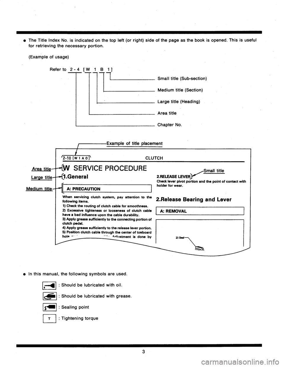
The
Title
Index
No
.
is
indicated
on
thetop
left
(or
right)
side
of
the
page
asthe
book
is
opened
.
This
is
useful
for
retrieving
the
necessary
portion
.
(Example
of
usage)
Refer
to
2
-
4
[
W
1
B
1
7
77
Small
title
(Sub-section)
2-tOfwI
no
Medium
title
(Section)
Large
title
(Heading)
Area
title
Chapter
Na
of
title
placement
CLUTCH
SERVICE
PROCEDURE
Large
title
.General
11
A
:
PRECAUTION
I
When
servicing
clutch
system,
pay
attention
tothe
following
items
.
t)
Check
the
routing
ofclutch
cable
for
smoothness
.
2)
Excessive
tighteness
or
looseness
of
clutch
cable
have
a
bad
influence
upon
the
cable
durability
.
3)
Apply
grease
sufficiently
to
the
connecting
portion
ofclutch
pedal
.
4)
Apply
grease
sufficiently
to
the
release
leverportion
.
5)
Position
clutch
cable
through
the
center
of
toBboard
hole
-
'
`
A
.+anstment
is
done
by
In
this
manual,
thefollowing
symbols
are
used
.
Shouldbe
lubricated
with
oil
.
Shouldbe
lubricated
with
grease
.
Sealing
point
Tightening
torque
Small
title
2
.RELEASE
LEVER
Check
leverpivot
portion
and
the
point
of
contact
with
holder
for
wear
.
2
.Release
Bearing
and
Lever
A
:
REMOVAL
2)
Seal
3
Page 220 of 2890
![SUBARU LEGACY 1996 Service Repair Manual
ON-BOARD
DIAGNOSTICS
11
SYSTEM
[T10A0]
2-7
10
.
Diagnostics
Chart
with
Trouble
Code
DTC
No
.
Abbreviation
(Subaru
select
monitor)Item
Page
P0500
VSP
Vehicle
speed
sensor
malfunction
1
P0505
I SUBARU LEGACY 1996 Service Repair Manual
ON-BOARD
DIAGNOSTICS
11
SYSTEM
[T10A0]
2-7
10
.
Diagnostics
Chart
with
Trouble
Code
DTC
No
.
Abbreviation
(Subaru
select
monitor)Item
Page
P0500
VSP
Vehicle
speed
sensor
malfunction
1
P0505
I](/manual-img/17/57433/w960_57433-219.png)
ON-BOARD
DIAGNOSTICS
11
SYSTEM
[T10A0]
2-7
10
.
Diagnostics
Chart
with
Trouble
Code
DTC
No
.
Abbreviation
(Subaru
select
monitor)Item
Page
P0500
VSP
Vehicle
speed
sensor
malfunction
'1
P0505
ISC
Idle
control
system
malfunction
`1
P0506
ISC
-
L
Idle
control
system
RPM
lower
than
expected
'1
P0507
ISC
-
H
Idle
control
system
RPM
higher
than
expected
'1
P0600
-
Serial
communication
link
malfunction
`1
P0601
RAM
Internal
control
module
memory
check
sum
error
'1
P0703
ATBRK
Brake
switch
input
malfunction
'1
P0705
ATRNG
Transmissionrange
sensor
circuit
malfunction
`1
P0710
ATF
Transmission
fluid
temperature
sensor
circuit
malfunction
'1
P0720
ATVSP
Output
speed
sensor
(vehicle
speed
sensor
1)
circuit
malfunction
'1
P0725
ATNE
Engine
speed
input
circuit
malfunction
'1
P0731
ATGR1
Gear
1
incorrect
ratio
P0732
ATGR2
Gear
2
incorrect
ratio
"
1
P0733
ATGR3
Gear
3
incorrect
ratio
P0734
ATGR4
Gear
4
incorrect
ratio
P0740
ATLU
-
F
Torque
converter
clutch
system
malfunction
1
P0743
ATLU
Torque
converter
clutch
system
electrical
*1
P0748
ATPL
Pressure
control
solenoid
electrical
'1
P0753
ATSFTi
Shift
solenoid
A
electrical
`1
P0758
ATSFT2
Shift
solenoid
B
electrical
'1
P0760
ATOVR
-
F
Shift
solenoid
C
malfunction
'1
P0763
ATOVR
Shift
solenoid
C
electrical
'1
P1100
ST-SW
Starter
switch
circuit
malfunction
'1
P1101
N/P
-
SW
Neutral
position
switch
circuit
malfunction
[MT
vehicles]
'1
P1101
N/P
-
SW
Neutral
position
switch
circuit
malfunction
[AT
vehicles]
1
P1102
BR
Pressure
sources
switching
solenoid
valve
circuit
malfunction
'1
P1103
TRQ
Engine
torque
control
signal
circuit
malfunction
`1
P1400
PCVSOL
Fueltank
pressure
control
solenoid
valve
circuit
malfunction
38
P1401
PCV
-
FFueltank
pressure
control
system
function
problem
44
P1402
FIVL
Fuel
level
sensor
circuit
malfunction
46
P1500
FAN
-
1
Radiator
fan
relay
1
circuit
malfunction
'1
P1502
FAN
-
F
Radiator
fan
function
problem
'1
P1700
ATTH
Throttle
position
sensor
circuit
malfunction
for
automatic
transmission
'1
P1701
ATCRS
Cruise
control
set
signal
circuit
malfunction
for
automatic
transmission
'1
P1702
ATDIAG
Automatic
transmission
diagnosis
inputsignal
circuit
malfunction
'1
P0461'2
EXERR22
Fuel
level
sensor
circuit
range/performance
problem
56
"1
:
<
Ref
.
to
2-7
[T11A0]
.*4
>
'2
:
Only
OBD-II
general
scan
tool
displays
DTC
.
Page 319 of 2890
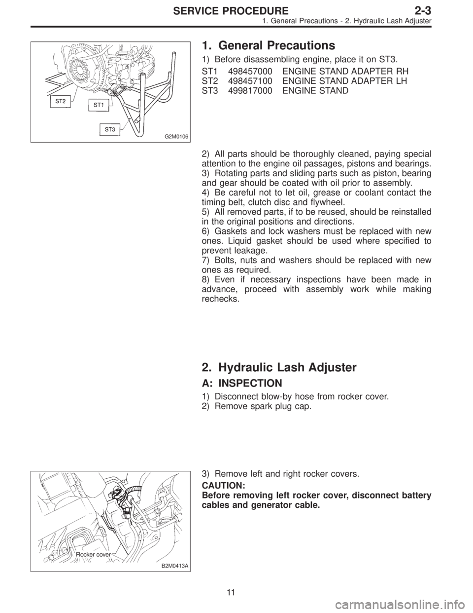
G2M0106
1. General Precautions
1) Before disassembling engine, place it on ST3.
ST1 498457000 ENGINE STAND ADAPTER RH
ST2 498457100 ENGINE STAND ADAPTER LH
ST3 499817000 ENGINE STAND
2) All parts should be thoroughly cleaned, paying special
attention to the engine oil passages, pistons and bearings.
3) Rotating parts and sliding parts such as piston, bearing
and gear should be coated with oil prior to assembly.
4) Be careful not to let oil, grease or coolant contact the
timing belt, clutch disc and flywheel.
5) All removed parts, if to be reused, should be reinstalled
in the original positions and directions.
6) Gaskets and lock washers must be replaced with new
ones. Liquid gasket should be used where specified to
prevent leakage.
7) Bolts, nuts and washers should be replaced with new
ones as required.
8) Even if necessary inspections have been made in
advance, proceed with assembly work while making
rechecks.
2. Hydraulic Lash Adjuster
A: INSPECTION
1) Disconnect blow-by hose from rocker cover.
2) Remove spark plug cap.
B2M0413A
3) Remove left and right rocker covers.
CAUTION:
Before removing left rocker cover, disconnect battery
cables and generator cable.
11
2-3SERVICE PROCEDURE
1. General Precautions - 2. Hydraulic Lash Adjuster