Page 4 of 2890
2-1
IM9-0)
EMISSION
CONTROL
SYSTEM
AND
VACUUM
FITTING
9
.
Vacuum
Fitting
9
.
Vacuum
Fitting
The
hose
and
pipe
connections
of
intake
manifold,
throttle
body
and
related
parts
are
as
shown
in
the
illustration
.
OSE
IPE
B2H0901A
Pressure
regulator
D
Pressuresources
switching
solenoid
valve
Throttle
body
OO
EGR
solenoid
valve
OO
Purge
control
solenoid
valve
(7)
EGR
valve
40
Pressuresensor
OO
BPT
OOFilter
2
Page 248 of 2890
ON-BOARD
DIAGNOSTICS
II
SYSTEM
[T1oBT11
2-7
10
.
DiagnosticsChart
with
Trouble
Code
(CHECK
PRESSURE/VACUUM
LINE
.
Is
therea
fault
in
pressurelvacuum
line?
NOTE
:
Check
the
following
items
.
9
Disconnection,
leakage
and
clogging
of
the
vacuum
hoses
and
pipes
between
fuel
tank
pressure
sensor
and
fuel
tank
e
Disconnection,
leakage
and
clogging
of
air
ventilation
hoses
and
pipes
between
fuel
filler
pipe
and
fuel
tank
vES
:
Repair
or
replace
hoses
and
pipes
.
No
:
Replace
fuel
tankpressure
sensor
.
37
Page 287 of 2890
4) Installation is in the reverse order of removal.
Tightening torque:
16±1.5 N⋅m (1.6±0.15 kg-m, 11.6±1.1 ft-lb)
B2M0423
5. EGR Valve
A: REMOVAL AND INSTALLATION
1) Disconnect vacuum hose from EGR valve.
2) Remove bolts which install EGR valve onto intake mani-
fold.
3) Installation is in the reverse order of removal.
CAUTION:
Replace gasket with a new one.
Tightening torque:
17.1 — 20.1 N⋅m (1.74 — 2.05 kg-m, 12.6 — 14.8
ft-lb)
B2M0424
6. Back-Pressure Transducer (BPT)
A: REMOVAL AND INSTALLATION
1) Disconnect vacuum hoses from BPT.
2) Remove BPT from bracket.
3) Installation is in the reverse order of removal.
8
2-1SERVICE PROCEDURE
4. Purge Control Solenoid Valve - 6. Back-Pressure Transducer (BPT)
Page 288 of 2890
4) Installation is in the reverse order of removal.
Tightening torque:
16±1.5 N⋅m (1.6±0.15 kg-m, 11.6±1.1 ft-lb)
B2M0423
5. EGR Valve
A: REMOVAL AND INSTALLATION
1) Disconnect vacuum hose from EGR valve.
2) Remove bolts which install EGR valve onto intake mani-
fold.
3) Installation is in the reverse order of removal.
CAUTION:
Replace gasket with a new one.
Tightening torque:
17.1 — 20.1 N⋅m (1.74 — 2.05 kg-m, 12.6 — 14.8
ft-lb)
B2M0424
6. Back-Pressure Transducer (BPT)
A: REMOVAL AND INSTALLATION
1) Disconnect vacuum hoses from BPT.
2) Remove BPT from bracket.
3) Installation is in the reverse order of removal.
8
2-1SERVICE PROCEDURE
4. Purge Control Solenoid Valve - 6. Back-Pressure Transducer (BPT)
Page 289 of 2890
4) Installation is in the reverse order of removal.
Tightening torque:
16±1.5 N⋅m (1.6±0.15 kg-m, 11.6±1.1 ft-lb)
B2M0423
5. EGR Valve
A: REMOVAL AND INSTALLATION
1) Disconnect vacuum hose from EGR valve.
2) Remove bolts which install EGR valve onto intake mani-
fold.
3) Installation is in the reverse order of removal.
CAUTION:
Replace gasket with a new one.
Tightening torque:
17.1 — 20.1 N⋅m (1.74 — 2.05 kg-m, 12.6 — 14.8
ft-lb)
B2M0424
6. Back-Pressure Transducer (BPT)
A: REMOVAL AND INSTALLATION
1) Disconnect vacuum hoses from BPT.
2) Remove BPT from bracket.
3) Installation is in the reverse order of removal.
8
2-1SERVICE PROCEDURE
4. Purge Control Solenoid Valve - 6. Back-Pressure Transducer (BPT)
Page 297 of 2890
G6M0095
11. Vent Control Solenoid Valve (2200
cc AWD Model)
A: REMOVAL
1) Disconnect battery ground cable.
B2M0964
2) Lift-up the vehicle.
3) Remove canister.
4) Disconnect two hoses from air filter.
5) Disconnect connector from vent control solenoid valve.
H2M1469
6) Remove one bolt fixing bracket on the body.
B2M0965A
7) Remove two vacuum hoses from vent control solenoid
valve.
B2M0966
8) Remove one bolt fixing vent control solenoid valve on
bracket.
9) Remove vent control solenoid valve.
13
2-1SERVICE PROCEDURE
11. Vent Control Solenoid Valve (2200 cc AWD Model)
Page 298 of 2890
B2M0966
B: INSTALLATION
1) Install the bolt fixing vent control solenoid valve on
bracket.
B2M0965A
2) Install two vacuum hoses to vent control solenoid valve.
H2M1469
3) Install the bolt fixing bracket on the body.
Tightening torque:
25±7 N⋅m (2.5±0.7 kg-m, 18.1±5.1 ft-lb)
B2M0964
4) Connect connector to vent control solenoid valve.
5) Connect two hoses to air filter.
6) Install canister.
7) Let down the vehicle.
G6M0095
8) Connect battery ground cable.
14
2-1SERVICE PROCEDURE
11. Vent Control Solenoid Valve (2200 cc AWD Model)
Page 307 of 2890

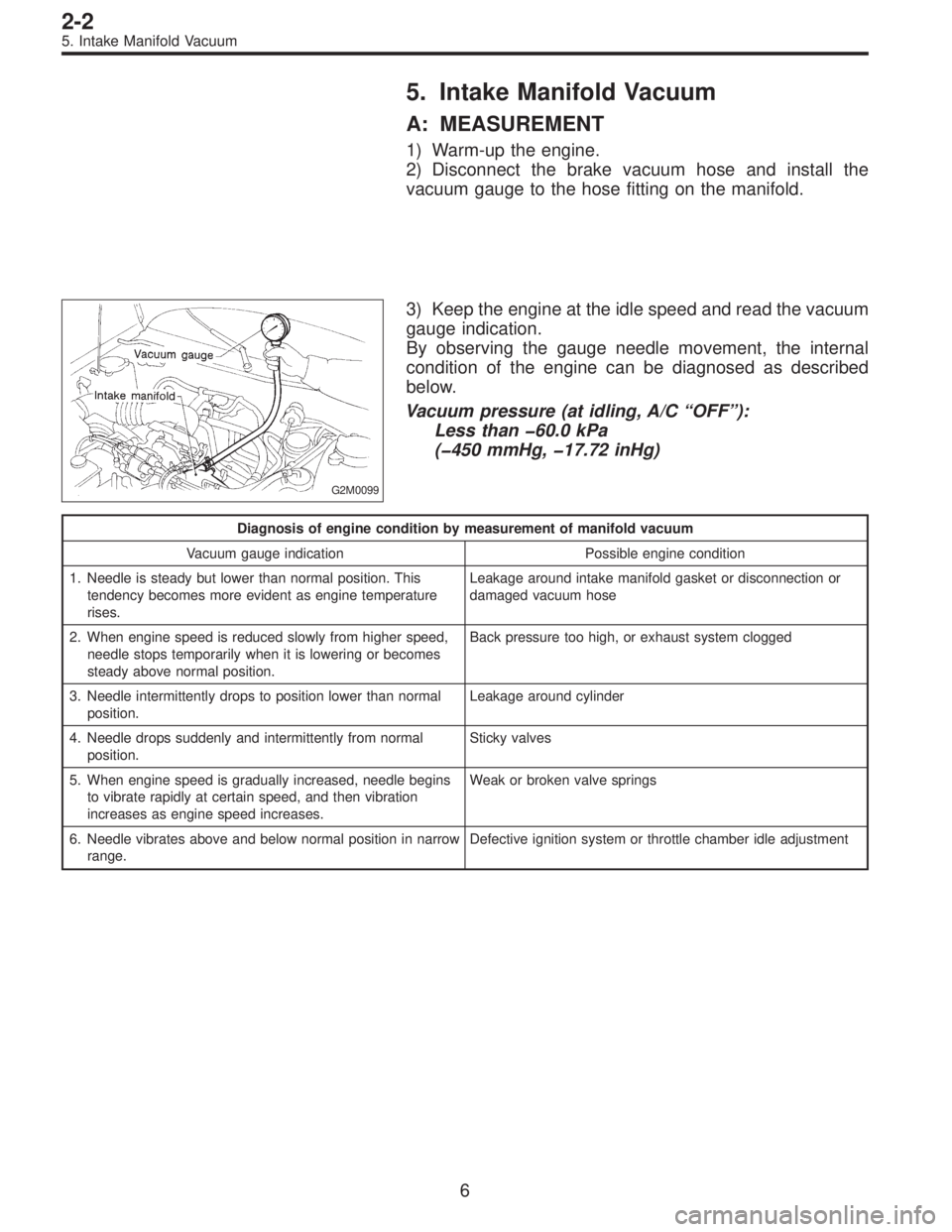
5. Intake Manifold Vacuum
A: MEASUREMENT
1) Warm-up the engine.
2) Disconnect the brake vacuum hose and install the
vacuum gauge to the hose fitting on the manifold.
G2M0099
3) Keep the engine at the idle speed and read the vacuum
gauge indication.
By observing the gauge needle movement, the internal
condition of the engine can be diagnosed as described
below.
Vacuum pressure (at idling, A/C“OFF”):
Less than �60.0 kPa
(�450 mmHg, �17.72 inHg)
Diagnosis of engine condition by measurement of manifold vacuum
Vacuum gauge indication Possible engine condition
1. Needle is steady but lower than normal position. This
tendency becomes more evident as engine temperature
rises.Leakage around intake manifold gasket or disconnection or
damaged vacuum hose
2. When engine speed is reduced slowly from higher speed,
needle stops temporarily when it is lowering or becomes
steady above normal position.Back pressure too high, or exhaust system clogged
3. Needle intermittently drops to position lower than normal
position.Leakage around cylinder
4. Needle drops suddenly and intermittently from normal
position.Sticky valves
5. When engine speed is gradually increased, needle begins
to vibrate rapidly at certain speed, and then vibration
increases as engine speed increases.Weak or broken valve springs
6. Needle vibrates above and below normal position in narrow
range.Defective ignition system or throttle chamber idle adjustment
6
2-2
5. Intake Manifold Vacuum