Page 1393 of 2890
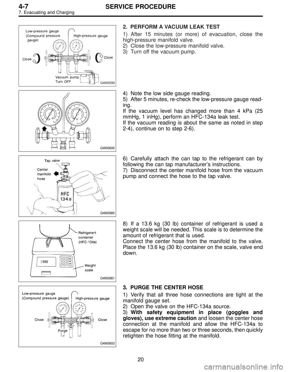
G4M0599
2. PERFORM A VACUUM LEAK TEST
1) After 15 minutes (or more) of evacuation, close the
high-pressure manifold valve.
2) Close the low-pressure manifold valve.
3) Turn off the vacuum pump.
G4M0600
4) Note the low side gauge reading.
5) After 5 minutes, re-check the low-pressure gauge read-
ing.
If the vacuum level has changed more than 4 kPa (25
mmHg, 1 inHg), perform an HFC-134a leak test.
If the vacuum reading is about the same as noted in step
2-4), continue on to step 2-6).
G4M0980
6) Carefully attach the can tap to the refrigerant can by
following the can tap manufacturer’s instructions.
7) Disconnect the center manifold hose from the vacuum
pump and connect the hose to the tap valve.
G4M0981
8) If a 13.6 kg (30 lb) container of refrigerant is used a
weight scale will be needed. This scale is to determine the
amount of refrigerant that is used.
Connect the center hose from the manifold to the valve.
Place the 13.6 kg (30 lb) container on the scale, valve end
down.
G4M0603
3. PURGE THE CENTER HOSE
1) Verify that all three hose connections are tight at the
manifold gauge set.
2) Open the valve on the HFC-134a source.
3)With safety equipment in place (goggles and
gloves), use extreme cautionand loosen the center hose
connection at the manifold and allow the HFC-134a to
escape for no more than two or three seconds, then quickly
retighten the hose fitting at the manifold.
20
4-7SERVICE PROCEDURE
7. Evacuating and Charging
Page 1713 of 2890
B6M0358
3) Remove nuts which secure actuator.
4) Remove actuator while disconnecting vacuum hose.
Tightening torque:
7.4±1.5 N⋅m (0.75±0.15 kg-m, 5.4±1.1 ft-lb)
B6M0359A
4. VACUUM PUMP AND VALVES
1) Disconnect connector from vacuum pump.
2) Remove bolts which secure vacuum pump.
3) Remove A/C receiver/drier bracket.
4) Remove vacuum pump while disconnecting vacuum
hose.
Tightening torque:
7.4±1.5 N⋅m (0.75±0.15 kg-m, 5.4±1.1 ft-lb)
5. STOP AND BRAKE SWITCH
Refer to 4-5 [C100] (MT) or 4-5 [C200] (AT) as for removal
and installation of stop and brake switch.
6. CLUTCH SWITCH (MT)
Refer to 4-5 [C100] as for removal and installation of clutch
switch.
7. INHIBITOR SWITCH (AT)
Refer to 3-2 [W4A3] as for removal and installation of
inhibitor switch.
G6M0095
8. CRUISE CONTROL MODULE
1) Disconnect battery ground cable.
B3M0377A
2) Remove lower cover and then disconnect connector.
49
6-2SERVICE PROCEDURE
21. Cruise Control
Page 1910 of 2890
B2M0654
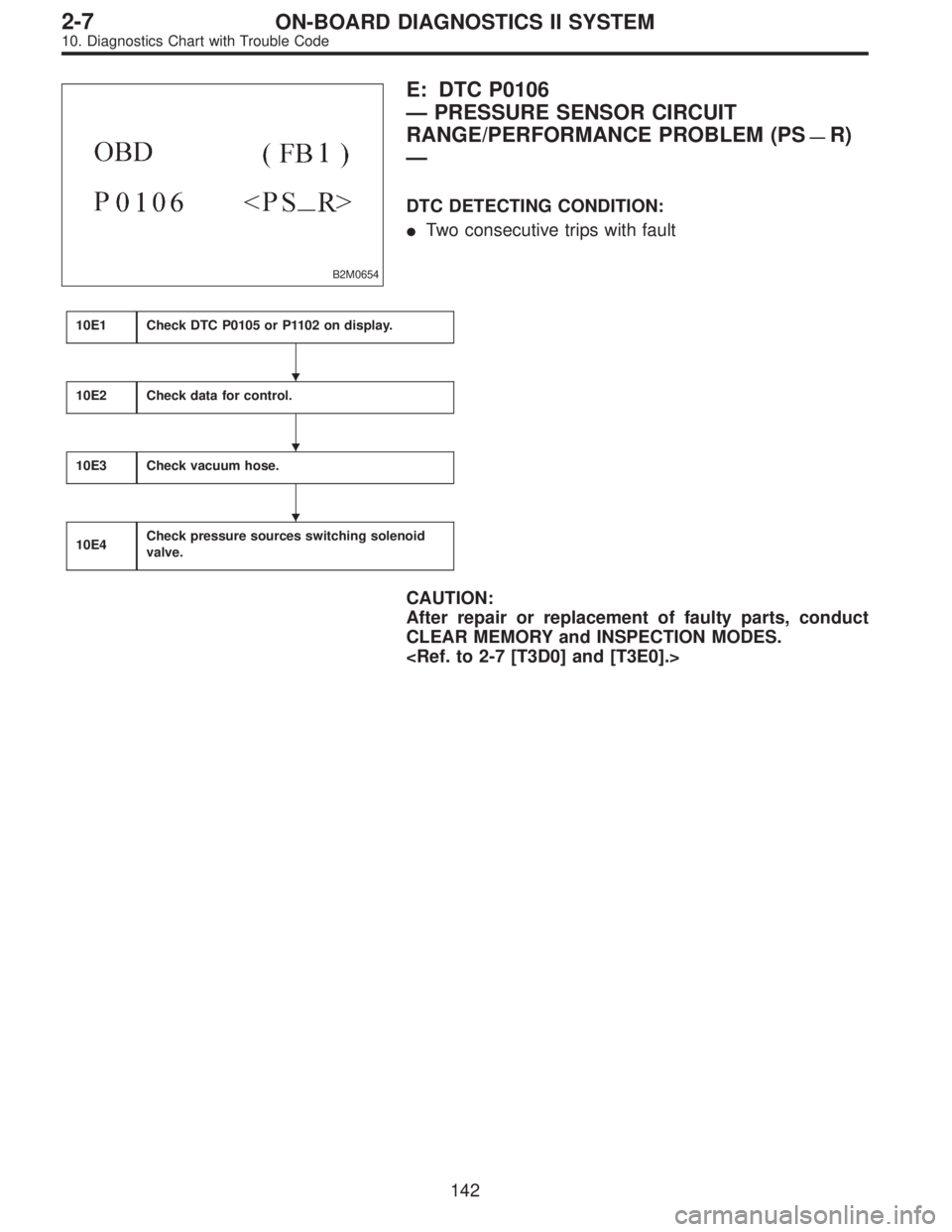
E: DTC P0106
—PRESSURE SENSOR CIRCUIT
RANGE/PERFORMANCE PROBLEM (PS
—R)
—
DTC DETECTING CONDITION:
�Two consecutive trips with fault
10E1Check DTC P0105 or P1102 on display.
10E2Check data for control.
10E3Check vacuum hose.
10E4Check pressure sources switching solenoid
valve.
CAUTION:
After repair or replacement of faulty parts, conduct
CLEAR MEMORY and INSPECTION MODES.
�
�
�
142
2-7ON-BOARD DIAGNOSTICS II SYSTEM
10. Diagnostics Chart with Trouble Code
Page 1914 of 2890
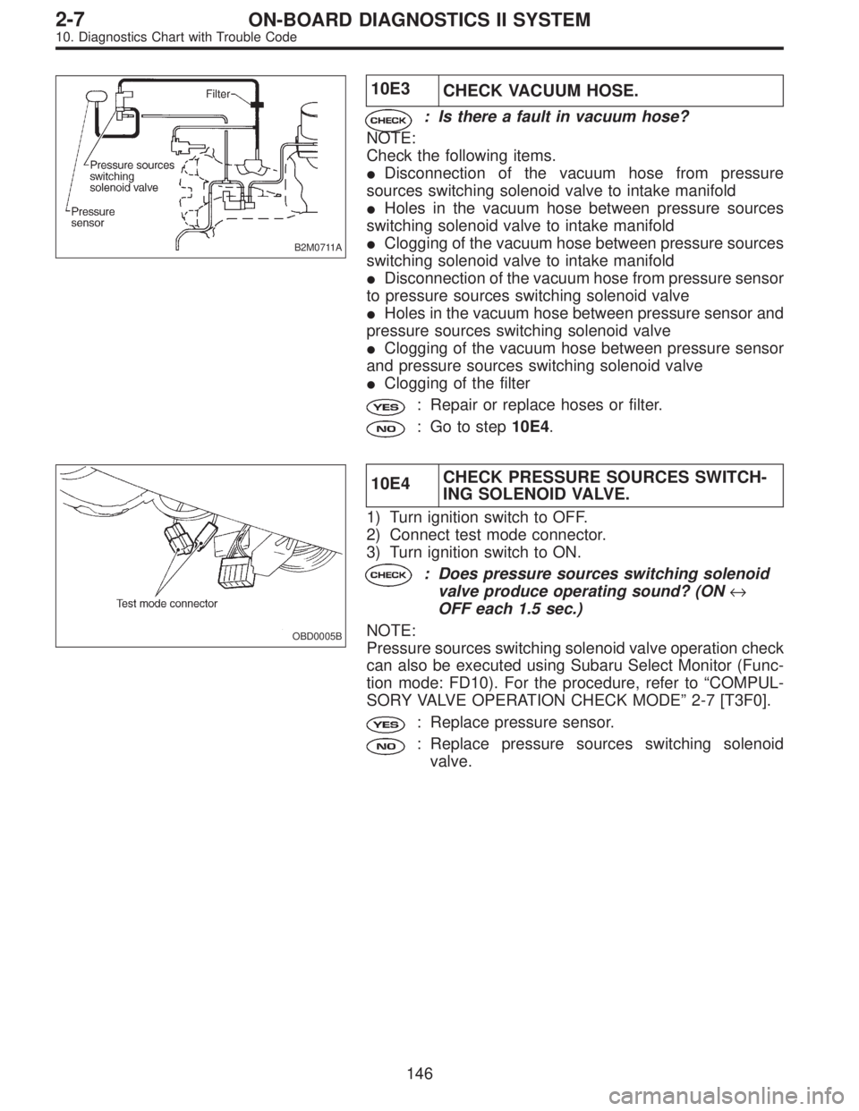
B2M0711A
10E3
CHECK VACUUM HOSE.
: Is there a fault in vacuum hose?
NOTE:
Check the following items.
�Disconnection of the vacuum hose from pressure
sources switching solenoid valve to intake manifold
�Holes in the vacuum hose between pressure sources
switching solenoid valve to intake manifold
�Clogging of the vacuum hose between pressure sources
switching solenoid valve to intake manifold
�Disconnection of the vacuum hose from pressure sensor
to pressure sources switching solenoid valve
�Holes in the vacuum hose between pressure sensor and
pressure sources switching solenoid valve
�Clogging of the vacuum hose between pressure sensor
and pressure sources switching solenoid valve
�Clogging of the filter
: Repair or replace hoses or filter.
: Go to step10E4.
OBD0005B
10E4CHECK PRESSURE SOURCES SWITCH-
ING SOLENOID VALVE.
1) Turn ignition switch to OFF.
2) Connect test mode connector.
3) Turn ignition switch to ON.
: Does pressure sources switching solenoid
valve produce operating sound? (ON↔
OFF each 1.5 sec.)
NOTE:
Pressure sources switching solenoid valve operation check
can also be executed using Subaru Select Monitor (Func-
tion mode: FD10). For the procedure, refer to“COMPUL-
SORY VALVE OPERATION CHECK MODE”2-7 [T3F0].
: Replace pressure sensor.
: Replace pressure sources switching solenoid
valve.
146
2-7ON-BOARD DIAGNOSTICS II SYSTEM
10. Diagnostics Chart with Trouble Code
Page 1955 of 2890
OBD0711
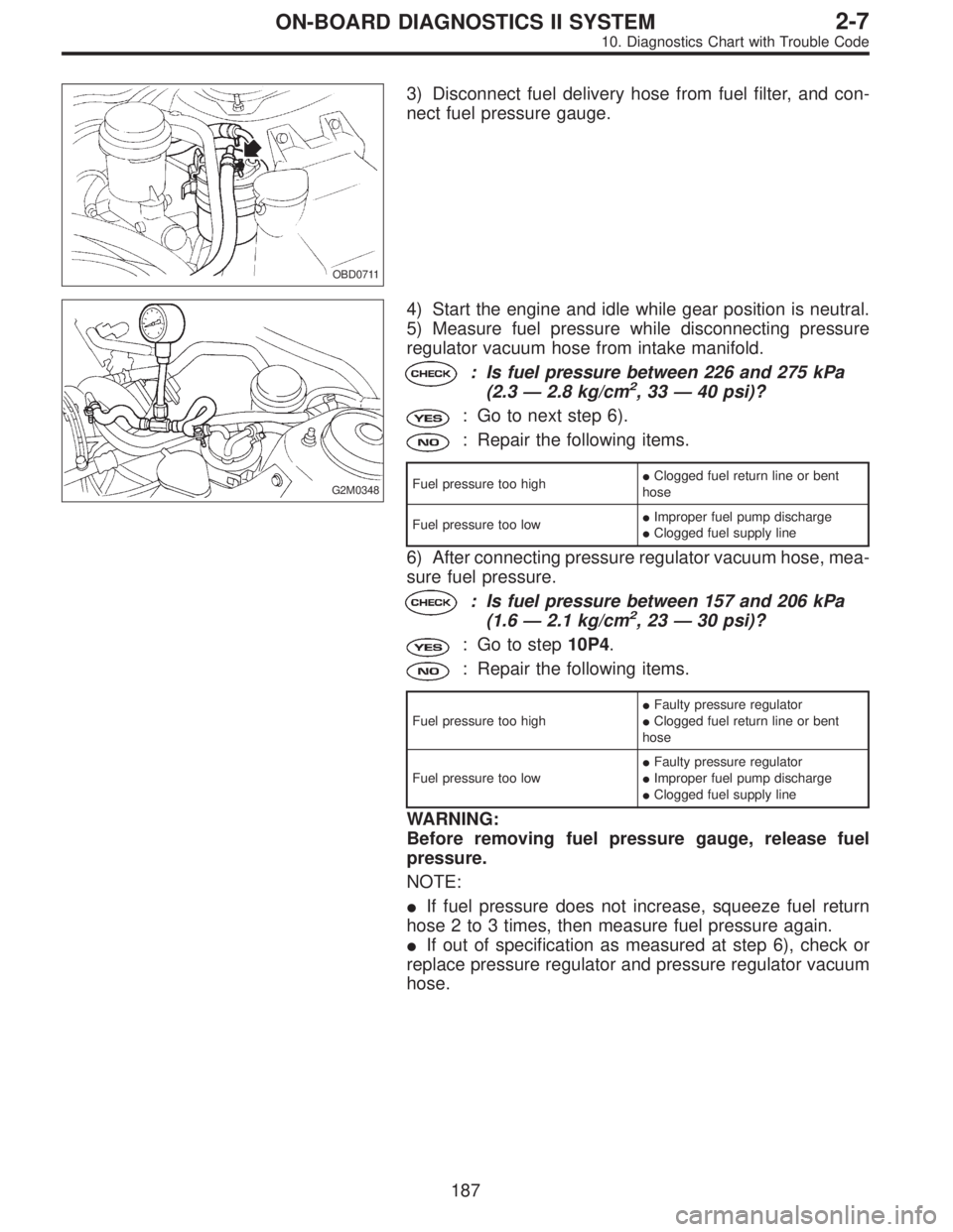
3) Disconnect fuel delivery hose from fuel filter, and con-
nect fuel pressure gauge.
G2M0348
4) Start the engine and idle while gear position is neutral.
5) Measure fuel pressure while disconnecting pressure
regulator vacuum hose from intake manifold.
: Is fuel pressure between 226 and 275 kPa
(2.3—2.8 kg/cm2,33—40 psi)?
: Go to next step 6).
: Repair the following items.
Fuel pressure too high�Clogged fuel return line or bent
hose
Fuel pressure too low�Improper fuel pump discharge
�Clogged fuel supply line
6) After connecting pressure regulator vacuum hose, mea-
sure fuel pressure.
: Is fuel pressure between 157 and 206 kPa
(1.6—2.1 kg/cm2,23—30 psi)?
: Go to step10P4.
: Repair the following items.
Fuel pressure too high�Faulty pressure regulator
�Clogged fuel return line or bent
hose
Fuel pressure too low�Faulty pressure regulator
�Improper fuel pump discharge
�Clogged fuel supply line
WARNING:
Before removing fuel pressure gauge, release fuel
pressure.
NOTE:
�If fuel pressure does not increase, squeeze fuel return
hose 2 to 3 times, then measure fuel pressure again.
�If out of specification as measured at step 6), check or
replace pressure regulator and pressure regulator vacuum
hose.
187
2-7ON-BOARD DIAGNOSTICS II SYSTEM
10. Diagnostics Chart with Trouble Code
Page 1992 of 2890
B2M0647A
10AD3
CHECK VACUUM LINE.
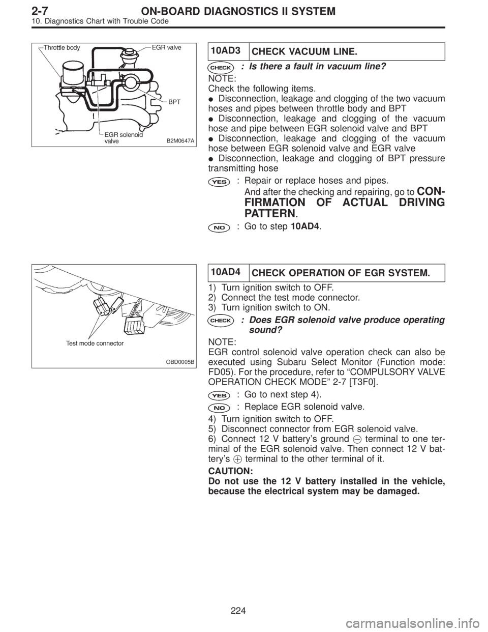
: Is there a fault in vacuum line?
NOTE:
Check the following items.
�Disconnection, leakage and clogging of the two vacuum
hoses and pipes between throttle body and BPT
�Disconnection, leakage and clogging of the vacuum
hose and pipe between EGR solenoid valve and BPT
�Disconnection, leakage and clogging of the vacuum
hose between EGR solenoid valve and EGR valve
�Disconnection, leakage and clogging of BPT pressure
transmitting hose
: Repair or replace hoses and pipes.
And after the checking and repairing, go to
CON-
FIRMATION OF ACTUAL DRIVING
PATTERN.
: Go to step10AD4.
OBD0005B
10AD4
CHECK OPERATION OF EGR SYSTEM.
1) Turn ignition switch to OFF.
2) Connect the test mode connector.
3) Turn ignition switch to ON.
: Does EGR solenoid valve produce operating
sound?
NOTE:
EGR control solenoid valve operation check can also be
executed using Subaru Select Monitor (Function mode:
FD05). For the procedure, refer to“COMPULSORY VALVE
OPERATION CHECK MODE”2-7 [T3F0].
: Go to next step 4).
: Replace EGR solenoid valve.
4) Turn ignition switch to OFF.
5) Disconnect connector from EGR solenoid valve.
6) Connect 12 V battery’s ground�terminal to one ter-
minal of the EGR solenoid valve. Then connect 12 V bat-
tery’s�terminal to the other terminal of it.
CAUTION:
Do not use the 12 V battery installed in the vehicle,
because the electrical system may be damaged.
224
2-7ON-BOARD DIAGNOSTICS II SYSTEM
10. Diagnostics Chart with Trouble Code
Page 2033 of 2890
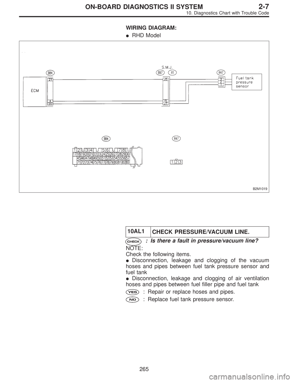
WIRING DIAGRAM:
�RHD Model
B2M1019
10AL1
CHECK PRESSURE/VACUUM LINE.
: Is there a fault in pressure/vacuum line?
NOTE:
Check the following items.
�Disconnection, leakage and clogging of the vacuum
hoses and pipes between fuel tank pressure sensor and
fuel tank
�Disconnection, leakage and clogging of air ventilation
hoses and pipes between fuel filler pipe and fuel tank
: Repair or replace hoses and pipes.
: Replace fuel tank pressure sensor.
265
2-7ON-BOARD DIAGNOSTICS II SYSTEM
10. Diagnostics Chart with Trouble Code
Page 2039 of 2890
10AN1
CHECK AIR INTAKE SYSTEM.
1) Turn ignition switch to ON.
2) Start engine, and idle it.
: Is there a fault in air intake system?
NOTE:
Check the following items.
�Loose installation of intake manifold, idle air control sole-
noid valve and throttle body
�Cracks of intake manifold gasket, idle air control sole-
noid valve gasket and throttle body gasket
�Loose connections and cracks of idle air control solenoid
valve by-pass hoses
�Disconnections of vacuum hoses
: Repair or replace air intake system.
: Go to step10AN2.
B2M0576A
10AN2
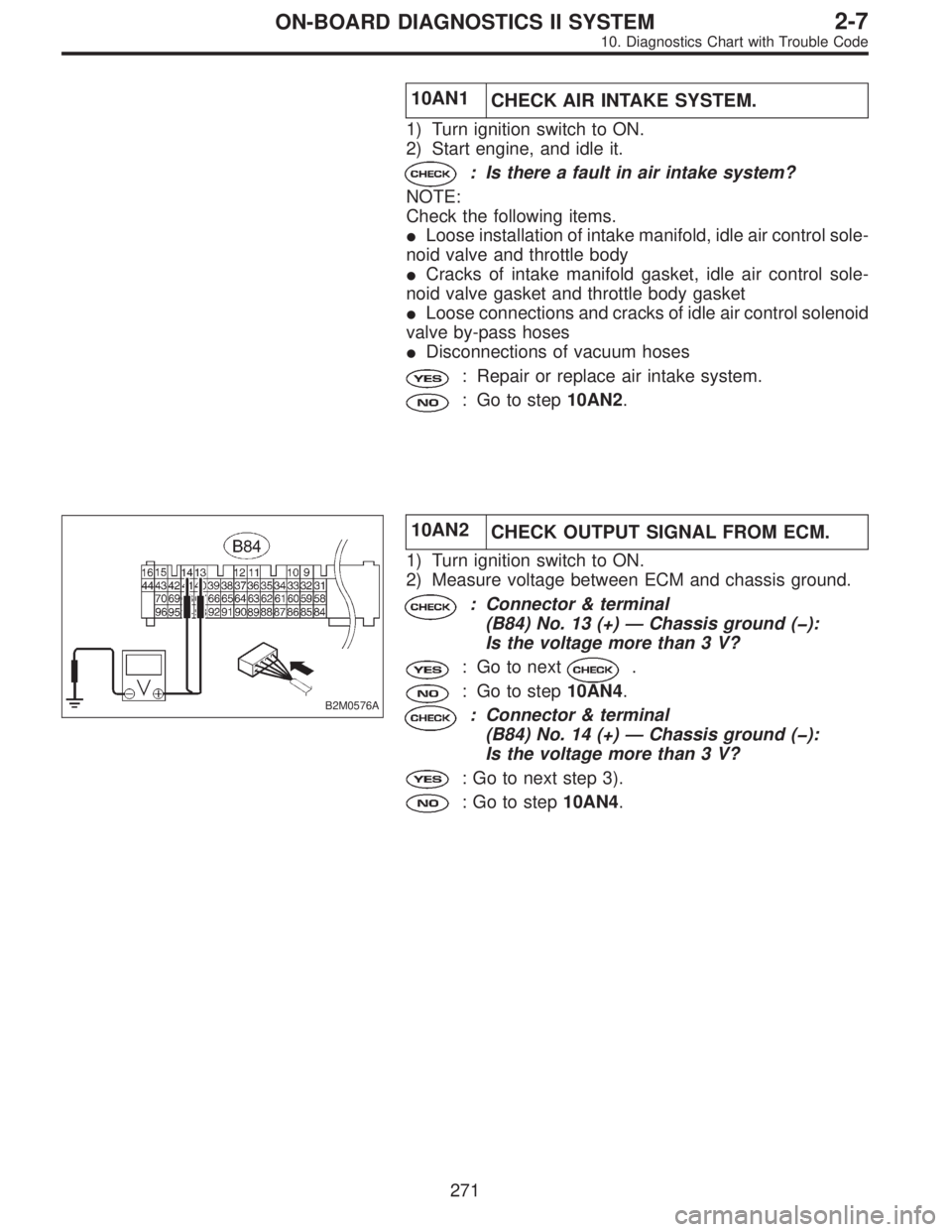
CHECK OUTPUT SIGNAL FROM ECM.
1) Turn ignition switch to ON.
2) Measure voltage between ECM and chassis ground.
: Connector & terminal
(B84) No. 13 (+)—Chassis ground ():
Is the voltage more than 3 V?
: Go to next.
: Go to step10AN4.
: Connector & terminal
(B84) No. 14 (+)—Chassis ground ():
Is the voltage more than 3 V?
: Go to next step 3).
: Go to step10AN4.
271
2-7ON-BOARD DIAGNOSTICS II SYSTEM
10. Diagnostics Chart with Trouble Code