Page 315 of 2890
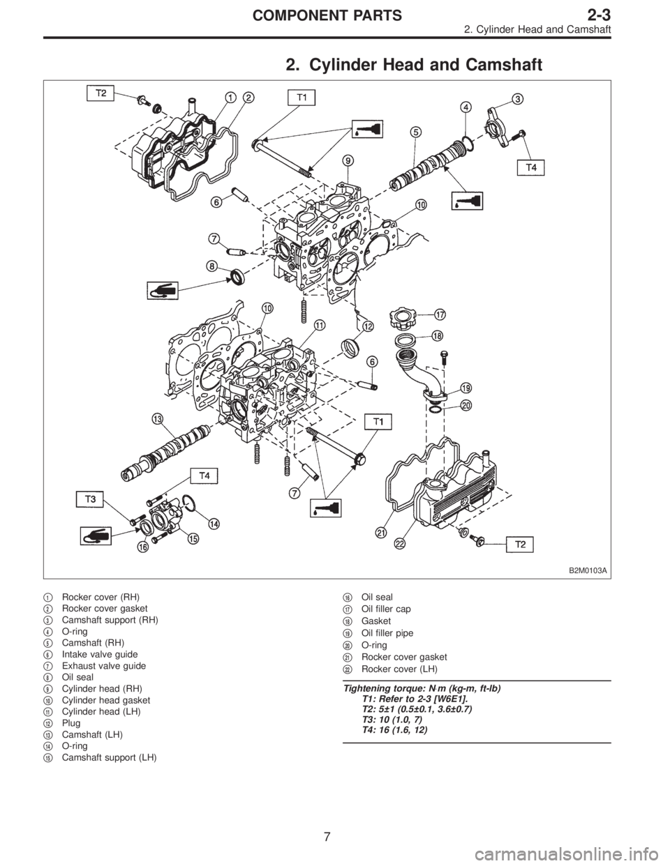
2. Cylinder Head and Camshaft
B2M0103A
�1Rocker cover (RH)
�
2Rocker cover gasket
�
3Camshaft support (RH)
�
4O-ring
�
5Camshaft (RH)
�
6Intake valve guide
�
7Exhaust valve guide
�
8Oil seal
�
9Cylinder head (RH)
�
10Cylinder head gasket
�
11Cylinder head (LH)
�
12Plug
�
13Camshaft (LH)
�
14O-ring
�
15Camshaft support (LH)�
16Oil seal
�
17Oil filler cap
�
18Gasket
�
19Oil filler pipe
�
20O-ring
�
21Rocker cover gasket
�
22Rocker cover (LH)
Tightening torque: N⋅m (kg-m, ft-lb)
T1: Refer to 2-3 [W6E1].
T2: 5±1 (0.5±0.1, 3.6±0.7)
T3: 10 (1.0, 7)
T4: 16 (1.6, 12)
7
2-3COMPONENT PARTS
2. Cylinder Head and Camshaft
Page 387 of 2890
TROUBLE
Engine will not start.
Rough idle and engine stall
Low output, hesitation and poor acceleration
Surging
Engine does not return to idle.
Dieseling (Run-on)
After burning in exhaust system
Knocking
Excessive engine oil consumption
Excessive fuel consumption Starter does not turn.
Initial combustion does not occur.
Initial combustion occurs.
Engine stalls after initial combustion.
LUBRICATION SYSTEM
22 3 3�Incorrect oil pressure
2�Loosened oil pump attaching bolts and defective
gasket
2�Defective oil filter seal
2�Defective crankshaft oil seal
32�Defective rocker cover gasket
2�Loosened oil drain plug or defective gasket
2�Loosened oil pan fitting bolts or defective oil pan
COOLING SYSTEM
33221�Overheating
333�Over cooling
OTHERS
113 3�Malfunction of Evaporative Emission Control
System
21�Stuck or damaged throttle valve
322 2�Accelerator cable out of adjustment
77
2-3DIAGNOSTICS
1. Engine Trouble in General
Page 395 of 2890

�
2Rocker cover gasket (RH)
�
3Oil separator cover
�
4Gasket
�
5Intake camshaft cap (Front RH)
�
6Intake camshaft cap (Center RH)
�
7Intake c")
2. Cylinder Head and Camshaft
B2M0681A
�1Rocker cover (RH)
�
2Rocker cover gasket (RH)
�
3Oil separator cover
�
4Gasket
�
5Intake camshaft cap (Front RH)
�
6Intake camshaft cap (Center RH)
�
7Intake camshaft cap (Rear RH)
�
8Intake camshaft (RH)
�
9Exhaust camshaft cap (Front RH)
�
10Exhaust camshaft cap (Center RH)
�
11Exhaust camshaft cap (Rear RH)
�
12Exhaust camshaft (RH)
�
13Intake valve guide�
14Exhaust valve guide
�
15Cylinder head bolt
�
16Oil seal
�
17Cylinder head (RH)
�
18Cylinder head gasket (RH)
�
19Cylinder head gasket (LH)
�
20Cylinder head (LH)
�
21Intake camshaft (LH)
�
22Exhaust camshaft (LH)
�
23Intake camshaft cap (Front LH)
�
24Intake camshaft cap (Center LH)
�
25Intake camshaft cap (Rear LH)
�
26Exhaust camshaft (Front LH)�
27Exhaust camshaft cap (Center LH)
�
28Exhaust camshaft cap (Rear LH)
�
29Rocker cover gasket (LH)
�
30Rocker cover (LH)
�
31Oil filler cap
�
32Gasket
�
33Oil filler duct
�
34Gasket
Tightening torque: N⋅m (kg-m, ft-lb)
T1: Refer to 2-3b [W4E1].
T2: 5 (0.5, 3.6)
T3: 10 (1.0, 7)
7
2-3bCOMPONENT PARTS
2. Cylinder Head and Camshaft
Page 465 of 2890
TROUBLE
Engine will not start.
Rough idle and engine stall
Low output, hesitation and poor acceleration
Surging
Engine does not return to idle.
Dieseling (Run-on)
After burning in exhaust system
Knocking
Excessive engine oil consumption
Excessive fuel consumption Starter does not turn.
Initial combustion does not occur.
Initial combustion occurs.
Engine stalls after initial combustion.
LUBRICATION SYSTEM
22 3 3�Incorrect oil pressure
2�Loosened oil pump attaching bolts and defective
gasket
2�Defective oil filter seal
2�Defective crankshaft oil seal
32�Defective rocker cover gasket
2�Loosened oil drain plug or defective gasket
2�Loosened oil pan fitting bolts or defective oil pan
COOLING SYSTEM
33221�Overheating
333�Over cooling
OTHERS
113 3�Malfunction of Evaporative Emission Control
System
21�Stuck or damaged throttle valve
322 2�Accelerator cable out of adjustment
77
2-3bDIAGNOSTICS
1. Engine Trouble in General
Page 495 of 2890

G2M0213
C: INSTALLATION
Installation is in the reverse order of removal.
CAUTION:
�Replace gasket with a new one.
�When installing engine coolant pump, tighten bolts
in two stages in numerical sequence as shown in fig-
ure.
Tightening torque:
10
+4
�0N⋅m (1.0+0.4
�0kg-m, 7.2+2.9
�0ft-lb)
G2M0214
3. Thermostat
A: REMOVAL AND INSTALLATION
1) Drain engine coolant.
Set container under the vehicle, and remove drain cock
from radiator.
2) Disconnect radiator outlet hose from thermostat cover.
3) Remove thermostat cover and gasket, and pull out the
thermostat.
G2M0227
4) Install the thermostat in the intake manifold, and install
the thermostat cover together with a gasket.
CAUTION:
�When reinstalling the thermostat, use a new gasket.
�The thermostat must be installed with the jiggle pin
upward.
�In this time, set the jiggle pin of thermostat for front
side.
G2M0215
B: INSPECTION
Replace the thermostat if the valve does not close com-
pletely at an ambient temperature or if the following test
shows unsatisfactory results.
Immerse the thermostat and a thermometer in water. Raise
water temperature gradually, and measure the temperature
and valve lift when the valve begins to open and when the
valve is fully opened. During the test, agitate the water for
even temperature distribution. The measurement should
be to the specification.
Starts to open:
76.0—80.0°C (169—176°F)
Fully opens:
91°C (196°F)
12
2-5SERVICE PROCEDURE
2. Engine Coolant Pump - 3. Thermostat
Page 552 of 2890
1. Fuel Tank
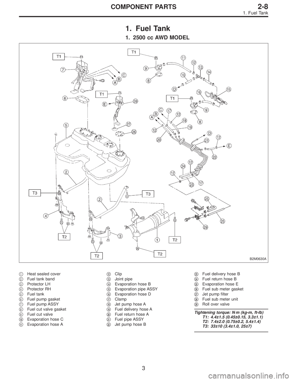
1. 2500 cc AWD MODEL
B2M0630A
�1Heat sealed cover
�
2Fuel tank band
�
3Protector LH
�
4Protector RH
�
5Fuel tank
�
6Fuel pump gasket
�
7Fuel pump ASSY
�
8Fuel cut valve gasket
�
9Fuel cut valve
�
10Evaporation hose C
�
11Evaporation hose A�
12Clip
�
13Joint pipe
�
14Evaporation hose B
�
15Evaporation pipe ASSY
�
16Evaporation hose D
�
17Clamp
�
18Jet pump hose A
�
19Fuel delivery hose A
�
20Fuel return hose A
�
21Fuel pipe ASSY
�
22Jet pump hose B�
23Fuel delivery hose B
�
24Fuel return hose B
�
25Evaporation hose E
�
26Fuel sub meter gasket
�
27Jet pump filter
�
28Fuel sub meter unit
�
29Roll over valve
Tightening torque: N⋅m (kg-m, ft-lb)
T1: 4.4±1.5 (0.45±0.15, 3.3±1.1)
T2: 7.4±2.0 (0.75±0.2, 5.4±1.4)
T3: 33±10 (3.4±1.0, 25±7)
3
2-8COMPONENT PARTS
1. Fuel Tank
Page 553 of 2890
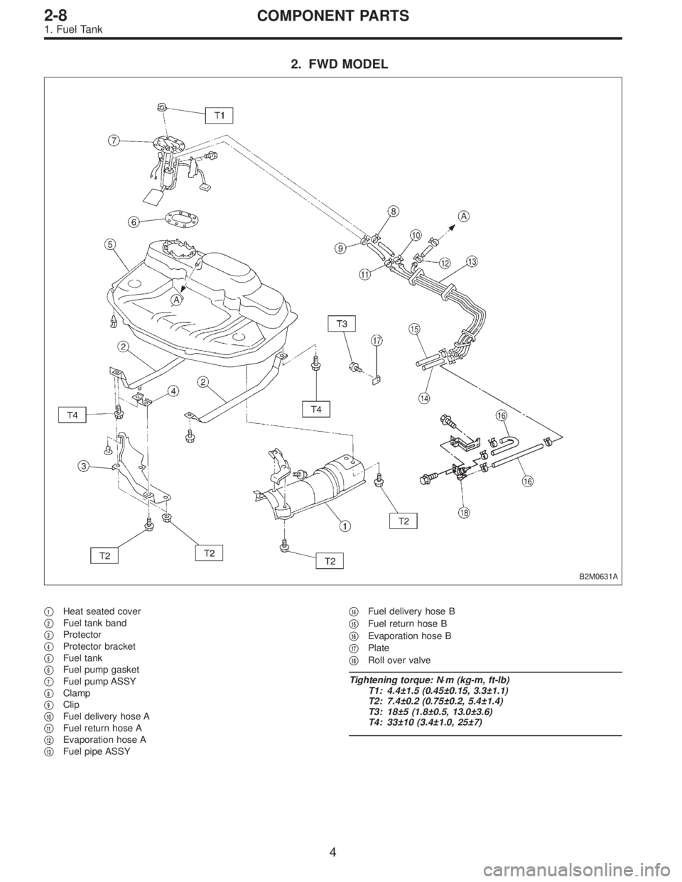
2. FWD MODEL
B2M0631A
�1Heat seated cover
�
2Fuel tank band
�
3Protector
�
4Protector bracket
�
5Fuel tank
�
6Fuel pump gasket
�
7Fuel pump ASSY
�
8Clamp
�
9Clip
�
10Fuel delivery hose A
�
11Fuel return hose A
�
12Evaporation hose A
�
13Fuel pipe ASSY�
14Fuel delivery hose B
�
15Fuel return hose B
�
16Evaporation hose B
�
17Plate
�
18Roll over valve
Tightening torque: N⋅m (kg-m, ft-lb)
T1: 4.4±1.5 (0.45±0.15, 3.3±1.1)
T2: 7.4±0.2 (0.75±0.2, 5.4±1.4)
T3: 18±5 (1.8±0.5, 13.0±3.6)
T4: 33±10 (3.4±1.0, 25±7)
4
2-8COMPONENT PARTS
1. Fuel Tank
Page 555 of 2890
�1Heat sealed cover
�
2Fuel tank band
�
3Protector LH
�
4Protector RH
�
5Fuel tank
�
6Pressure control solenoid valve bracket
�
7Pressure control solenoid valve
�
8Evaporation hose G
�
9Evaporation pipe A
�
10Fuel pump gasket
�
11Fuel pump ASSY
�
12Fuel cut valve gasket
�
13Fuel cut valve
�
14Evaporation hose C
�
15Evaporation hose A
�
16Clip
�
17Joint pipe
�
18Evaporation hose B
�
19Evaporation pipe ASSY�
20Evaporation hose D
�
21Evaporation hose E
�
22Clamp
�
23Jet pump hose A
�
24Fuel delivery hose A
�
25Fuel return hose A
�
26Fuel pipe ASSY
�
27Jet pump hose B
�
28Fuel delivery hose B
�
29Fuel return hose B
�
30Evaporation hose F
�
31Fuel sub meter gasket
�
32Jet pump filter
�
33Fuel sub meter unit
Tightening torque: N⋅m (kg-m, ft-lb)
T1: 4.4±1.5 (0.45±0.15, 3.3±1.1)
T2: 7.4±2.0 (0.75±0.2, 5.4±1.4)
T3: 33±10 (3.4±1.0, 25±7)
6
2-8COMPONENT PARTS
1. Fuel Tank

After burning in exhaust system
Knock")

After burning in exhaust system
Knock")