Page 16 of 2890

5-5b
[W7B1)
SERVICE
PROCEDURE
7
.
Combination
Switch
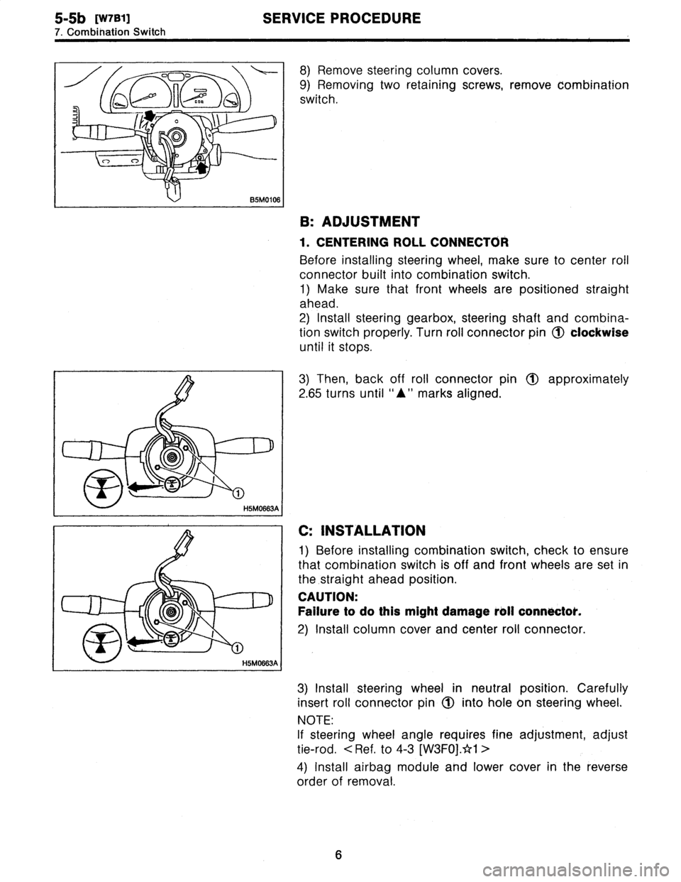
8)
Remove
steering
column
cowers
.
9)
Removing
two
retaining
screws,
remove
combination
switch
.
B
:
ADJUSTMENT
1
.
CENTERING
ROLL
CONNECTOR
Before
installing
steering
wheel,
make
sure
to
center
roil
connector
built
into
combination
switch
.
1)
Make
sure
that
front
wheels
are
positioned
straight
ahead
.
2)
Install
steering
gearbox,
steering
shaft
and
combina-
tion
switchproperly
.
Turn
roll
connector
pin
(J)
clockwise
until
it
stops
.
3)
Then,
back
off
roll
connector
pin
1~
approximately
2
.65
turns
until
"A"
marks
aligned
.
C
:
INSTALLATION
1)
Before
installing
combination
switch,
check
to
ensure
that
combination
switch
is
off
and
font
wheels
are
set
in
the
.straight
ahead
position
.
CAUTION
:
Failure
to
do
this
might
damage
roll
connoctok
.
2)
Install
column
cover
and
center
roll
connector
.
3)
Install
steering
wheel
in
neutral
position
.
Carefully
insert
roll
connector
pin
1(~
into
hole
on
steering
wheel
.
NOTE
:
If
steering
wheel
angle
requires
fine
adjustment,
adjust
tie-rod
.
<
Ref
.
to
4-3
[W3FOj
.*1
>
4)
Install
airbag
module
and
lower
cover
in
the
reverse
order
of
removal
.
6
Page 421 of 2890

B2M0764A
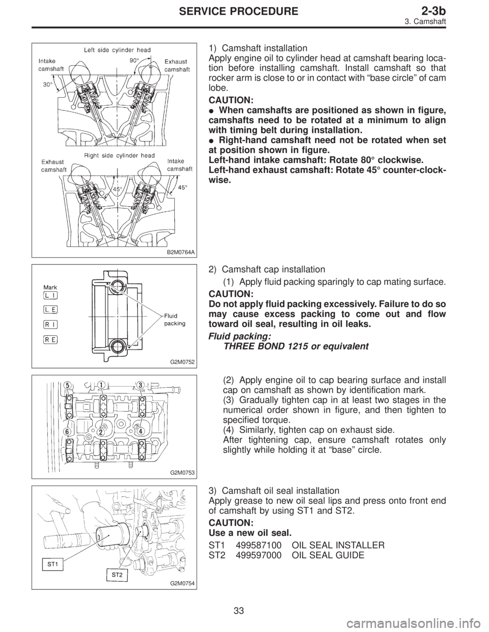
1) Camshaft installation
Apply engine oil to cylinder head at camshaft bearing loca-
tion before installing camshaft. Install camshaft so that
rocker arm is close to or in contact with“base circle”of cam
lobe.
CAUTION:
�When camshafts are positioned as shown in figure,
camshafts need to be rotated at a minimum to align
with timing belt during installation.
�Right-hand camshaft need not be rotated when set
at position shown in figure.
Left-hand intake camshaft: Rotate 80°clockwise.
Left-hand exhaust camshaft: Rotate 45°counter-clock-
wise.
G2M0752
2) Camshaft cap installation
(1) Apply fluid packing sparingly to cap mating surface.
CAUTION:
Do not apply fluid packing excessively. Failure to do so
may cause excess packing to come out and flow
toward oil seal, resulting in oil leaks.
Fluid packing:
THREE BOND 1215 or equivalent
G2M0753
(2) Apply engine oil to cap bearing surface and install
cap on camshaft as shown by identification mark.
(3) Gradually tighten cap in at least two stages in the
numerical order shown in figure, and then tighten to
specified torque.
(4) Similarly, tighten cap on exhaust side.
After tightening cap, ensure camshaft rotates only
slightly while holding it at“base”circle.
G2M0754
3) Camshaft oil seal installation
Apply grease to new oil seal lips and press onto front end
of camshaft by using ST1 and ST2.
CAUTION:
Use a new oil seal.
ST1 499587100 OIL SEAL INSTALLER
ST2 499597000 OIL SEAL GUIDE
33
2-3bSERVICE PROCEDURE
3. Camshaft
Page 933 of 2890
G3M0484
9) Install the one-way clutch (1-2) and plate, and secure
with the snap ring.
NOTE:
Set the inner race. Make sure that the forward clutch is free
in the clockwise direction and locked in the counterclock-
wise direction, as viewed from the front of the vehicle.
G3M0911
12. One-way Clutch Outer Race
A: DISASSEMBLY
Remove the snap ring. Then remove the one-way clutch
(3-4).
B: INSPECTION
Check the sliding surface and one-way clutch (3-4) for any
harmful cuts, damage, or other faults.
G3M0486
C: ASSEMBLY
1) Assemble the one-way clutch (3-4), and secure with the
snap ring.
NOTE:
Pay attention to the orientation of the one-way clutch (3-4).
2) Assemble the rear internal gear, and secure the outer
race. Make sure that the internal gear is locked in the
clockwise direction, and free to rotate in the counterclock-
wise direction.
105
3-2SERVICE PROCEDURE
11. Forward Clutch Drum - 12. One-Way Clutch Outer Race
Page 934 of 2890
G3M0484
9) Install the one-way clutch (1-2) and plate, and secure
with the snap ring.
NOTE:
Set the inner race. Make sure that the forward clutch is free
in the clockwise direction and locked in the counterclock-
wise direction, as viewed from the front of the vehicle.
G3M0911
12. One-way Clutch Outer Race
A: DISASSEMBLY
Remove the snap ring. Then remove the one-way clutch
(3-4).
B: INSPECTION
Check the sliding surface and one-way clutch (3-4) for any
harmful cuts, damage, or other faults.
G3M0486
C: ASSEMBLY
1) Assemble the one-way clutch (3-4), and secure with the
snap ring.
NOTE:
Pay attention to the orientation of the one-way clutch (3-4).
2) Assemble the rear internal gear, and secure the outer
race. Make sure that the internal gear is locked in the
clockwise direction, and free to rotate in the counterclock-
wise direction.
105
3-2SERVICE PROCEDURE
11. Forward Clutch Drum - 12. One-Way Clutch Outer Race
Page 1797 of 2890

OBD0006C
B: OBD-II GENERAL SCAN TOOL
1. HOW TO USE OBD-II GENERAL SCAN TOOL
1) Prepare a general scan tool (OBD-II general scan tool)
required by SAE J1978.
2) Open the cover and connect the OBD-II general scan
tool to the data link connector located in the lower portion
of the instrument panel (on the driver’s side), to the lower
cover.
3) Using the OBD-II general scan tool, call up diagnostic
trouble code(s) and freeze frame data.
OBD-II general scan tool functions consist of:
(1) MODE $01: Current powertrain diagnostic data
(2) MODE $02: Powertrain freeze frame data
(3) MODE $03: Emission-related powertrain diagnostic
trouble codes
(4) MODE $04: Clear/Reset emission-related diagnos-
tic information
(5) MODE $05: Oxygen sensor monitoring test results
Read out data according to repair procedures.
(For detailed operation procedures, refer to the OBD-II
General Scan Tool Operation Manual.)
NOTE:
For details concerning diagnostic trouble codes, refer to
the DIAGNOSTIC TROUBLE CODE (DTC) LIST, 2-7
[T10A0].
H2M1280
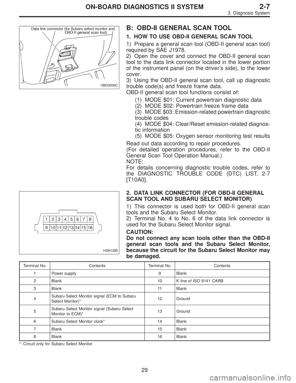
2. DATA LINK CONNECTOR (FOR OBD-II GENERAL
SCAN TOOL AND SUBARU SELECT MONITOR)
1) This connector is used both for OBD-II general scan
tools and the Subaru Select Monitor.
2) Terminal No. 4 to No. 6 of the data link connector is
used for the Subaru Select Monitor signal.
CAUTION:
Do not connect any scan tools other than the OBD-II
general scan tools and the Subaru Select Monitor,
because the circuit for the Subaru Select Monitor may
be damaged.
Terminal No. Contents Terminal No. Contents
1 Power supply 9 Blank
2 Blank 10 K line of ISO 9141 CARB
3 Blank 11 Blank
4Subaru Select Monitor signal (ECM to Subaru
Select Monitor)*12 Ground
5Subaru Select Monitor signal (Subaru Select
Monitor to ECM)*13 Ground
6 Subaru Select Monitor clock* 14 Blank
7 Blank 15 Blank
8 Blank 16 Blank
*: Circuit only for Subaru Select Monitor
29
2-7ON-BOARD DIAGNOSTICS II SYSTEM
3. Diagnosis System