Page 427 of 2890

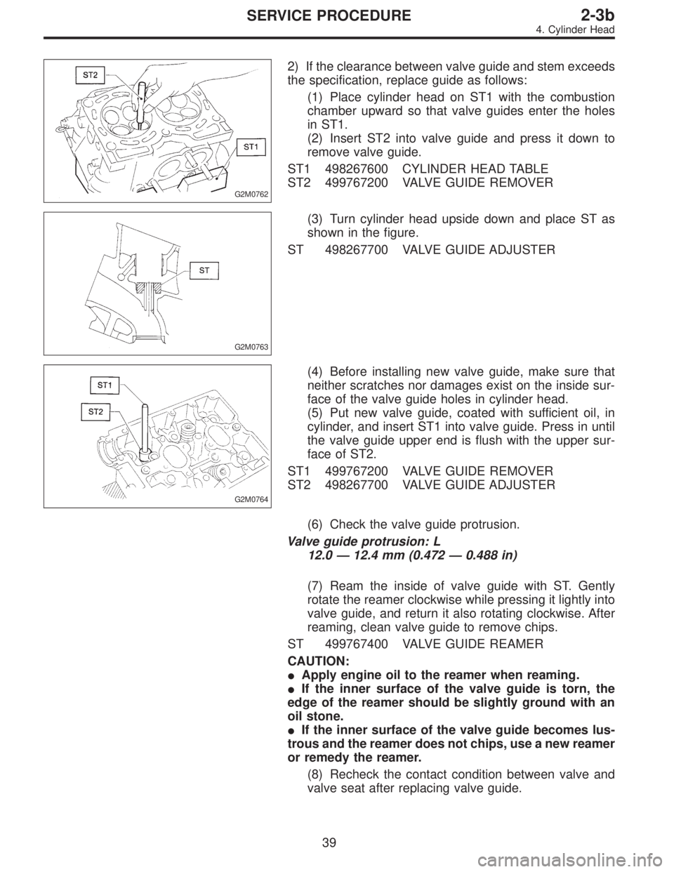
G2M0762
2) If the clearance between valve guide and stem exceeds
the specification, replace guide as follows:
(1) Place cylinder head on ST1 with the combustion
chamber upward so that valve guides enter the holes
in ST1.
(2) Insert ST2 into valve guide and press it down to
remove valve guide.
ST1 498267600 CYLINDER HEAD TABLE
ST2 499767200 VALVE GUIDE REMOVER
G2M0763
(3) Turn cylinder head upside down and place ST as
shown in the figure.
ST 498267700 VALVE GUIDE ADJUSTER
G2M0764
(4) Before installing new valve guide, make sure that
neither scratches nor damages exist on the inside sur-
face of the valve guide holes in cylinder head.
(5) Put new valve guide, coated with sufficient oil, in
cylinder, and insert ST1 into valve guide. Press in until
the valve guide upper end is flush with the upper sur-
face of ST2.
ST1 499767200 VALVE GUIDE REMOVER
ST2 498267700 VALVE GUIDE ADJUSTER
(6) Check the valve guide protrusion.
Valve guide protrusion: L
12.0—12.4 mm (0.472—0.488 in)
(7) Ream the inside of valve guide with ST. Gently
rotate the reamer clockwise while pressing it lightly into
valve guide, and return it also rotating clockwise. After
reaming, clean valve guide to remove chips.
ST 499767400 VALVE GUIDE REAMER
CAUTION:
�Apply engine oil to the reamer when reaming.
�If the inner surface of the valve guide is torn, the
edge of the reamer should be slightly ground with an
oil stone.
�If the inner surface of the valve guide becomes lus-
trous and the reamer does not chips, use a new reamer
or remedy the reamer.
(8) Recheck the contact condition between valve and
valve seat after replacing valve guide.
39
2-3bSERVICE PROCEDURE
4. Cylinder Head
Page 1020 of 2890
G4M0497
4) Connect stabilizer link to transverse link, and tempo-
rarily tighten bolts.
CAUTION:
Discard loosened self-locking nut and replace with a
new one.
5) Tighten the following points in the order shown below
when wheels are in full contact with the ground and vehicle
is at curb weight condition.
(1) Transverse link and stabilizer link
Tightening torque:
29±5 N⋅m (3.0±0.5 kg-m, 21.7±3.6 ft-lb)
(2) Transverse link and crossmember
Tightening torque:
98±15 N⋅m (10.0±1.5 kg-m, 72±11 ft-lb)
G4M0928
(3) Transverse link rear bushing and body
Tightening torque:
245±49 N⋅m (25±5 kg-m, 181±36 ft-lb)
NOTE:
�Move rear bushing back and forth until transverse link-
to-rear bushing clearance is established (as indicated in
figure.) before tightening.
�Check wheel alignment and adjust if necessary.
19
4-1SERVICE PROCEDURE
2. Front Transverse Link
Page 1503 of 2890

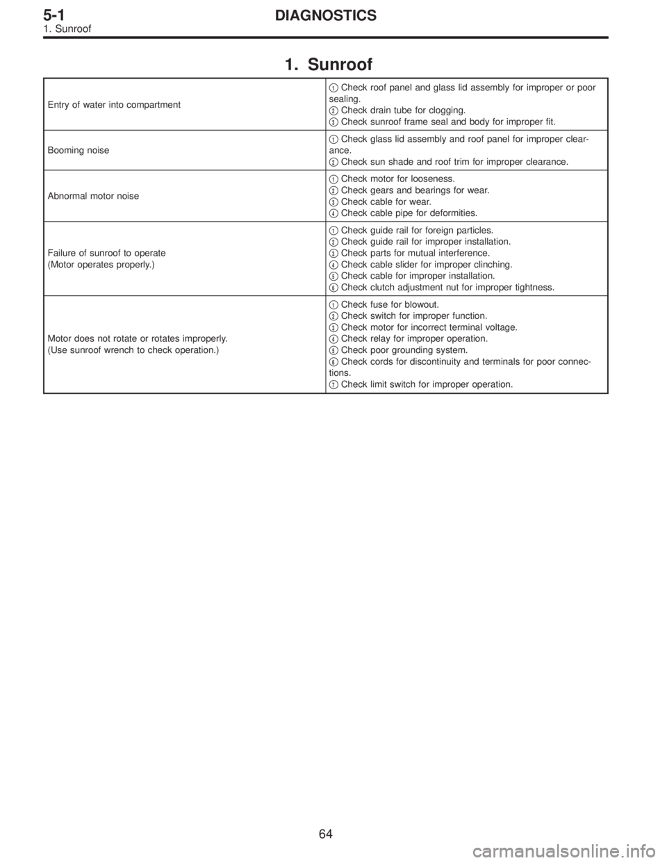
1. Sunroof
Entry of water into compartment�
1Check roof panel and glass lid assembly for improper or poor
sealing.
�
2Check drain tube for clogging.
�
3Check sunroof frame seal and body for improper fit.
Booming noise�
1Check glass lid assembly and roof panel for improper clear-
ance.
�
2Check sun shade and roof trim for improper clearance.
Abnormal motor noise�
1Check motor for looseness.
�
2Check gears and bearings for wear.
�
3Check cable for wear.
�
4Check cable pipe for deformities.
Failure of sunroof to operate
(Motor operates properly.)�
1Check guide rail for foreign particles.
�
2Check guide rail for improper installation.
�
3Check parts for mutual interference.
�
4Check cable slider for improper clinching.
�
5Check cable for improper installation.
�
6Check clutch adjustment nut for improper tightness.
Motor does not rotate or rotates improperly.
(Use sunroof wrench to check operation.)�
1Check fuse for blowout.
�
2Check switch for improper function.
�
3Check motor for incorrect terminal voltage.
�
4Check relay for improper operation.
�
5Check poor grounding system.
�
6Check cords for discontinuity and terminals for poor connec-
tions.
�
7Check limit switch for improper operation.
64
5-1DIAGNOSTICS
1. Sunroof
Page 1836 of 2890

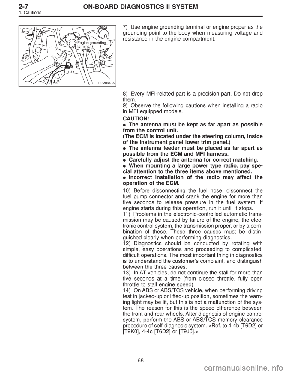
B2M0648A
7) Use engine grounding terminal or engine proper as the
grounding point to the body when measuring voltage and
resistance in the engine compartment.
8) Every MFI-related part is a precision part. Do not drop
them.
9) Observe the following cautions when installing a radio
in MFI equipped models.
CAUTION:
�The antenna must be kept as far apart as possible
from the control unit.
(The ECM is located under the steering column, inside
of the instrument panel lower trim panel.)
�The antenna feeder must be placed as far apart as
possible from the ECM and MFI harness.
�Carefully adjust the antenna for correct matching.
�When mounting a large power type radio, pay spe-
cial attention to the three items above mentioned.
�Incorrect installation of the radio may affect the
operation of the ECM.
10) Before disconnecting the fuel hose, disconnect the
fuel pump connector and crank the engine for more than
five seconds to release pressure in the fuel system. If
engine starts during this operation, run it until it stops.
11) Problems in the electronic-controlled automatic trans-
mission may be caused by failure of the engine, the elec-
tronic control system, the transmission proper, or by a com-
bination of these. These three causes must be distin-
guished clearly when performing diagnostics.
12) Diagnostics should be conducted by rotating with
simple, easy operations and proceeding to complicated,
difficult operations. The most important thing in diagnostics
is to understand the customer’s complaint, and distinguish
between the three causes.
13) In AT vehicles, do not continue the stall for more than
five seconds at a time (from closed throttle, fully open
throttle to stall engine speed).
14) On ABS or ABS/TCS vehicle, when performing driving
test in jacked-up or lifted-up position, sometimes the warn-
ing light may be lit, but this is not a malfunction of the sys-
tem. The reason for this is the speed difference between
the front and rear wheels. After diagnosis of engine control
system, perform the ABS or ABS/TCS memory clearance
procedure of self-diagnosis system.
[T9K0], 4-4c [T6D2] or [T9J0].>
68
2-7ON-BOARD DIAGNOSTICS II SYSTEM
4. Cautions