Page 35 of 2890
2-7
[T3C7]
ON-BOARD
DIAGNOSTICS
II
SYSTEM
3
.
Diagnosis
System
82M0476
7
.
FUNCTION
MODE
:
F00
-
ROM
ID
NUMBER
(YEAR)
-
CONDITION
:
Ignition
switch
"ON"
SPECIFIED
DATA
:
Presentation
display
Probable
cause
(Item
outside"specifieddata")
1
.
Error
1
2
.
Error2
vB
(F01)
12
.4
V
B2M0270
Probable
cause
(Item
outside
"specified
data")
1
.
Battery
1
2
.
Charging
system
1
3
.
Power
supply
line
Check
for
loose
or
disconnected
connector,
and
discontinued
circuit,
etc
.
Check
for
poor
contact
of
cartridge,
or
different
type
cartridge
.
8
.
FUNCTION
MODE
:
F01
-
BATTERY
VOLTAGE
(VB)
-
CONDITION
:
(1)
Ignition
switch
"ON"
(2)
Idling
after
warm-up
SPECIFIED
DATA
:
(1)
111
V
(2)
13
f
1
V
Check
battery
voltage
and
electrolyte's
specific
gravity
.
"
Check
regulating
voltage
.
(On
no-load)
Check
alternator
.
o
Check
main
relay
.
<
Ref
.
to
[T9C0]
.*4>
*
Check
harness
connector
of
ECM
power
supply
line
.
.
to
[T9C0]
.*4>
20
Page 49 of 2890
2-7
[T3C48]
ON-BOARD
DIAGNOSTICS
II
SYSTEM
3
.
Diagnosis
System
E-4AT
(F00)
4WD
1993
G3M0723
Probable
cause
(if
outside"specifieddata")
48
.
FUNCTION
MODE
:
F00
-
MODE
DISPLAY
-
SPECIFIED
DATA
:
Data
at
the
left
shouldbe
indicated
.
1
.
Communication
failure
(1)
Check
loose
or
poor
connectors,
or
(No
communication
method
can
be
confirmed
with
power
ON
.)
(2)
shortcircuit
.
Check
type
of
cartridge
.
2
.
Vehicle
types
cannot
be
identified
(due
to
communication
failure)
.
VB
(F01)
12
.7
V
OBD0673
1
.
Battery
1
2
.
Charging
system
Check
improper
cartridge
.
Replace
with
proper
one
.
49
.
FUNCTION
MODE
:
F01
-
BATTERY
VOLTAGE
(VB)
-
CONDITION
:
(1)
Ignition
switch
ON
(2)
Engine
idling
after
warm-up
SPECIFIED
DATA
:
(1)
12±1
V
(2)
13
±
1
V
Check
battery
voltage
and
specific
gravity
of
electrolyte
.
(1)
I
Measure
regulatingvoltage
under
no
loads
.
(2)
Check
generator
(as
asingle
unit)
.
34
Page 385 of 2890
1. Engine Trouble in General
Numbers shown in the chart refer to the possibility of reason for the
trouble in order (“Very often”to“Rarely”)
1—Very often
2—Sometimes
3—Rarely
TROUBLE
Engine will not start.
Rough idle and engine stall
Low output, hesitation and poor acceleration
Surging
Engine does not return to idle.
Dieseling (Run-on)
After burning in exhaust system
Knocking
Excessive engine oil consumption
Excessive fuel consumption Starter does not turn.
Initial combustion does not occur.
Initial combustion occurs.
Engine stalls after initial combustion.
POSSIBLE CAUSE
STARTER
2�Defective battery-to-starter harness
3�Defective starter switch
3�Defective inhibitor switch
23�Defective starter
BATTERY
1�Poor terminal connection
1�Run-down battery
2�Defective charging system
1111111111 1Fuel injection system
Diagnostics II System.>
75
2-3DIAGNOSTICS
1. Engine Trouble in General
Page 463 of 2890
1. Engine Trouble in General
Numbers shown in the chart refer to the possibility of reason for the
trouble in order (“Very often”to“Rarely”)
1—Very often
2—Sometimes
3—Rarely
TROUBLE
Engine will not start.
Rough idle and engine stall
Low output, hesitation and poor acceleration
Surging
Engine does not return to idle.
Dieseling (Run-on)
After burning in exhaust system
Knocking
Excessive engine oil consumption
Excessive fuel consumption Starter does not turn.
Initial combustion does not occur.
Initial combustion occurs.
Engine stalls after initial combustion.
POSSIBLE CAUSE
STARTER
2�Defective battery-to-starter harness
3�Defective starter switch
3�Defective inhibitor switch
23�Defective starter
BATTERY
1�Poor terminal connection
1�Run-down battery
2�Defective charging system
1111111111 1Fuel injection system
Diagnostics II System.>
75
2-3bDIAGNOSTICS
1. Engine Trouble in General
Page 1387 of 2890
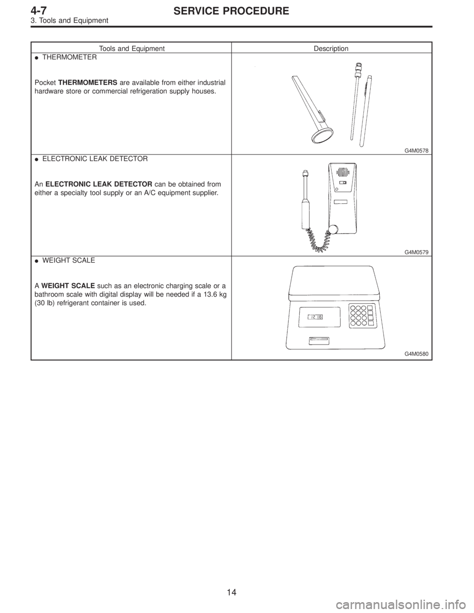
Tools and Equipment Description
�THERMOMETER
PocketTHERMOMETERSare available from either industrial
hardware store or commercial refrigeration supply houses.
G4M0578
�ELECTRONIC LEAK DETECTOR
AnELECTRONIC LEAK DETECTORcan be obtained from
either a specialty tool supply or an A/C equipment supplier.
G4M0579
�WEIGHT SCALE
AWEIGHT SCALEsuch as an electronic charging scale or a
bathroom scale with digital display will be needed if a 13.6 kg
(30 lb) refrigerant container is used.
G4M0580
14
4-7SERVICE PROCEDURE
3. Tools and Equipment
Page 1391 of 2890
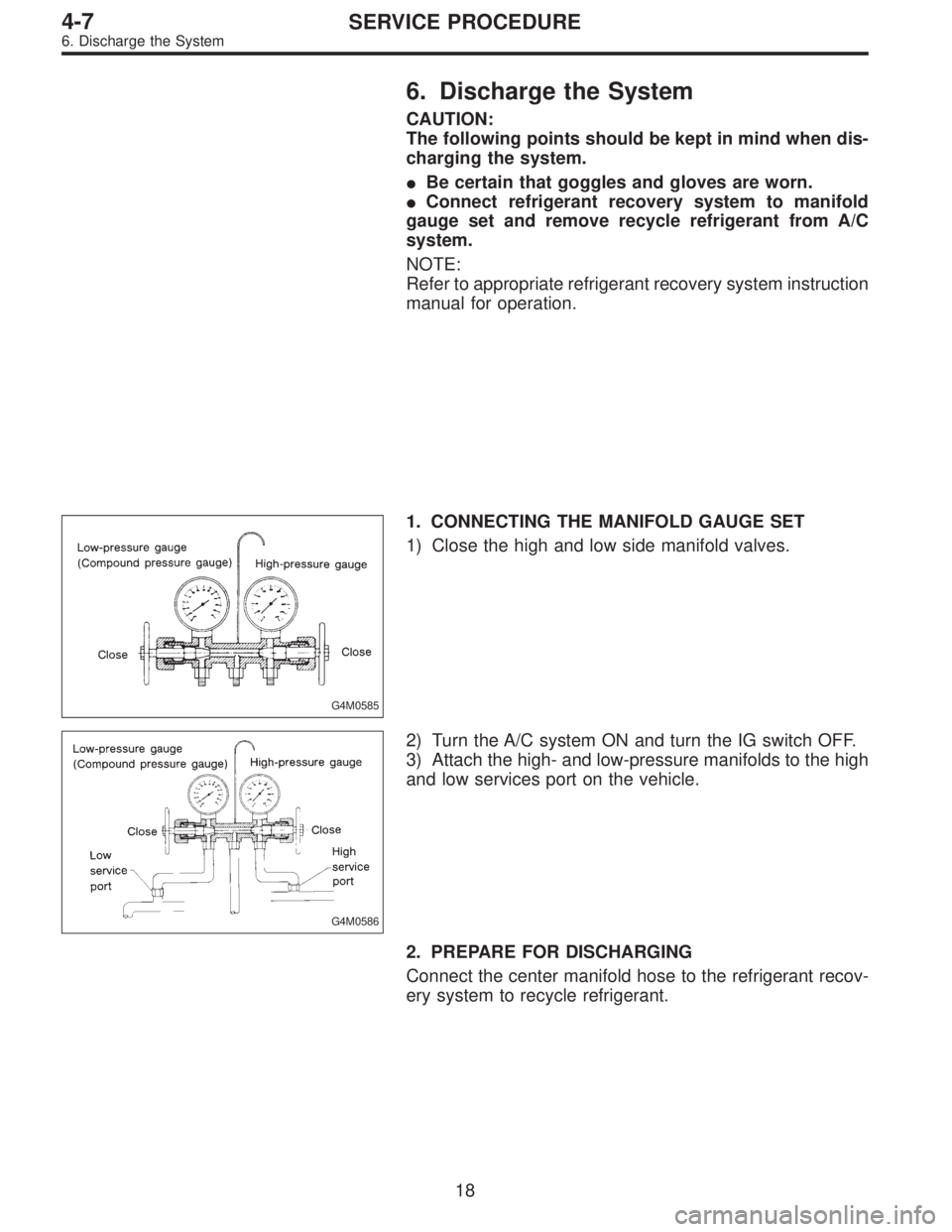
6. Discharge the System
CAUTION:
The following points should be kept in mind when dis-
charging the system.
�Be certain that goggles and gloves are worn.
�Connect refrigerant recovery system to manifold
gauge set and remove recycle refrigerant from A/C
system.
NOTE:
Refer to appropriate refrigerant recovery system instruction
manual for operation.
G4M0585
1. CONNECTING THE MANIFOLD GAUGE SET
1) Close the high and low side manifold valves.
G4M0586
2) Turn the A/C system ON and turn the IG switch OFF.
3) Attach the high- and low-pressure manifolds to the high
and low services port on the vehicle.
2. PREPARE FOR DISCHARGING
Connect the center manifold hose to the refrigerant recov-
ery system to recycle refrigerant.
18
4-7SERVICE PROCEDURE
6. Discharge the System
Page 1392 of 2890
 Be certain that goggles and gloves are worn.
2) If bulk refr")
G4M0596
7. Evacuating and Charging
The following points should be kept in mind when evacu-
ating and charging with a manifold gauge set.
1) Be certain that goggles and gloves are worn.
2) If bulk refrigerant [13.6 kg (30 lb) canister] is used, be
certain to weigh the charge amount carefully, using the
correct equipment, to avoid overcharging the system.
3) The charging procedure described in this section
begins by chargingliquidrefrigerant into the high- pres-
sure side of the systemwith the engine off.The proce-
dure is completed by charging refrigerantvaporinto the
low-pressure side of the system with the engine running.
CAUTION:
Never open the high-pressure manifold valve when the
engine is running.
G4M0597
1. CONNECT THE GAUGE SET
1) Close the high- and low-pressure manifold valves.
2) Attach the low-pressure manifold hose to the low- pres-
sure service port on the vehicle. Check the low- pressure
gauge. If more than 68.6 kPa (0.70 kg/cm
2, 10 psi) is
indicated, discharge the system prior to charging.
3) Attach the high-pressure manifold hose to the high-
pressure service port on the vehicle.
4) Connect the center hose from the manifold to the
vacuum pump.
5) Turn on the vacuum pump.
6) Slowly open the low-pressure manifold valve.
7) When the low-pressure gauge reaches approximately
66.43 kPa (498.3 mmHg, 19.62 inHg), slowly open the
high-pressure manifold valve.
G4M0598
8) Maintain a minimum vacuum level of 100.56 kPa (754.4
mmHg, 29.70 inHg) for a minimum of 15 minutes on a new
system or 30 minutes for an in-service system.
NOTE:
The gauge will read 4 kPa (25 mmHg, 1 inHg) less for
every 304.8 m (1,000 ft) above sea level.
19
4-7SERVICE PROCEDURE
7. Evacuating and Charging
Page 1393 of 2890
 After 15 minutes (or more) of evacuation, close the
high-pressure manifold valve.
2) Close the low-pressure manifold valve.
3) Turn off the vacuum pump.
G4M060")
G4M0599
2. PERFORM A VACUUM LEAK TEST
1) After 15 minutes (or more) of evacuation, close the
high-pressure manifold valve.
2) Close the low-pressure manifold valve.
3) Turn off the vacuum pump.
G4M0600
4) Note the low side gauge reading.
5) After 5 minutes, re-check the low-pressure gauge read-
ing.
If the vacuum level has changed more than 4 kPa (25
mmHg, 1 inHg), perform an HFC-134a leak test.
If the vacuum reading is about the same as noted in step
2-4), continue on to step 2-6).
G4M0980
6) Carefully attach the can tap to the refrigerant can by
following the can tap manufacturer’s instructions.
7) Disconnect the center manifold hose from the vacuum
pump and connect the hose to the tap valve.
G4M0981
8) If a 13.6 kg (30 lb) container of refrigerant is used a
weight scale will be needed. This scale is to determine the
amount of refrigerant that is used.
Connect the center hose from the manifold to the valve.
Place the 13.6 kg (30 lb) container on the scale, valve end
down.
G4M0603
3. PURGE THE CENTER HOSE
1) Verify that all three hose connections are tight at the
manifold gauge set.
2) Open the valve on the HFC-134a source.
3)With safety equipment in place (goggles and
gloves), use extreme cautionand loosen the center hose
connection at the manifold and allow the HFC-134a to
escape for no more than two or three seconds, then quickly
retighten the hose fitting at the manifold.
20
4-7SERVICE PROCEDURE
7. Evacuating and Charging
![SUBARU LEGACY 1996 Service Repair Manual
2-7
[T3C7]
ON-BOARD
DIAGNOSTICS
II
SYSTEM
3
.
Diagnosis
System
82M0476
7
.
FUNCTION
MODE
:
F00
-
ROM
ID
NUMBER
(YEAR)
-
CONDITION
:
Ignition
switch
"ON"
SPECIFIED
DATA
:
Presentation
display](/manual-img/17/57433/w960_57433-34.png "SUBARU LEGACY 1996 Service Repair Manual
2-7
[T3C7]
ON-BOARD
DIAGNOSTICS
II
SYSTEM
3
.
Diagnosis
System
82M0476
7
.
FUNCTION
MODE
:
F00
-
ROM
ID
NUMBER
(YEAR)
-
CONDITION
:
Ignition
switch
\"ON\"
SPECIFIED
DATA
:
Presentation
display")
![SUBARU LEGACY 1996 Service Repair Manual
2-7
[T3C48]
ON-BOARD
DIAGNOSTICS
II
SYSTEM
3
.
Diagnosis
System
E-4AT
(F00)
4WD
1993
G3M0723
Probable
cause
(if
outside"specifieddata")
48
.
FUNCTION
MODE
:
F00
-
MODE
DISPLAY
-
SPECIFIED
DATA](/manual-img/17/57433/w960_57433-48.png "SUBARU LEGACY 1996 Service Repair Manual
2-7
[T3C48]
ON-BOARD
DIAGNOSTICS
II
SYSTEM
3
.
Diagnosis
System
E-4AT
(F00)
4WD
1993
G3M0723
Probable
cause
(if
outside\"specifieddata\")
48
.
FUNCTION
MODE
:
F00
-
MODE
DISPLAY
-
SPECIFIED
DATA")

1—Very often
2—Sometimes
3—Rarely
TROUBLE
Eng")

1—Very often
2—Sometimes
3—Rarely
TROUBLE
Eng")