Page 64 of 2890
![SUBARU LEGACY 1996 Service Repair Manual
ON-BOARD
DIAGNOSTICS
II
SYSTEM
[TSAy]
2-7
6
.
Wiring
Diagram
and
Wiring
Harness
CrankshaftCamshaftpositionposition
sensorsensor
E10
I
E15
....
.
.
...
1
11
_..
.
..
._.J
r--
..
U)
33
3
:
E
1
---](/manual-img/17/57433/w960_57433-63.png "SUBARU LEGACY 1996 Service Repair Manual
ON-BOARD
DIAGNOSTICS
II
SYSTEM
[TSAy]
2-7
6
.
Wiring
Diagram
and
Wiring
Harness
CrankshaftCamshaftpositionposition
sensorsensor
E10
I
E15
....
.
.
...
1
11
_..
.
..
._.J
r--
..
U)
33
3
:
E
1
---")
ON-BOARD
DIAGNOSTICS
II
SYSTEM
[TSAy]
2-7
6
.
Wiring
Diagram
and
Wiring
Harness
CrankshaftCamshaftpositionposition
sensorsensor
E10
I
E15
....
.
.
...
1
11
_..
.
..
._.J
r--
..
U)
33
3
:
E
1
------------
-----------
-
m
M
~
B20
V1
1I1III
_
1
y
P
Iu+IN'"I
INI
II
Engine
control
B84
module
v
M
~~l
c
o
JJ
a
J
L
m
m
J3
F
Y
J
J
J
J
P1
H
JJ
L
m
;
~N
E3
4
}E17
~~
Eb
~
E16
~
E5
3E7
~~
A
E4
#4
#3#2
#1
Fuel
(nJector
Ely
(Dark
grey)
E10
(Gray)
12
E4
(B
I
ue)
E7
(Gray)
B20
(L
i
ght
grey)
12
123
123
456
BUR10-02D
Idle
air
control
Purge
control
solenoid
valve
solenoid
valve
B84
(Light
blue)
1
2
LI3
4
U
5
6U78U
1112
0
1314
1J
1516
1718
1920
21
22
23
24
252627282930
1
31
1
32
1
33
1
34
1
35
1
36~
1
37
1
38
1
39
1
401
41
1421
43
44
45
1
46
1
47
1
48
1
49
1
5
0
1
51
1
52
1
53
1
54,
~
5
1
56
1
57
1
8
626364
65
bb
6768
69
7071
7273
74
75
7
6
77
78
79
80
81
B283
1
84
1
65
1
86
1
87
1
88
1
89
1
90
1
91
1
92
1
93
1
94
1
95
1
96
(L
(
ght
gray)
E5
El6
(L
(
ght
gray)
(Darkgray)
E6
(O
(Dark
grey)
12
53
Page 190 of 2890
r
Area
No
.
Name
C-4
D1
Front
doorcord
RH
ow
C-4
ABi
SRS
(Airbag)
harness
;k
C-4
Turn
&
hazard
module
.k
C-3
i1
C-3
i2
instrument
panel
wiring
un
C-3
i3
harness
e
C-3
i4
y
C")
r
Connecting
to
)r
Area
No
.
Name
C-4
D1
Front
doorcord
RH
ow
C-4
ABi
SRS
(Airbag)
harness
;k
C-4
Turn
&
hazard
module
.k
C-3
i1
C-3
i2
instrument
panel
wiring
un
C-3
i3
harness
e
C-3
i4
y
C-3
OBD-IIservice
connector
C-3
Power
window
circuit
breaker
C-3
Power
window
relay
;k
C-3
Illuminationcontrol
module
C-3
Seat
belt
timer
;n
B-4
Fuel
pump
relay
vn
B-4
Main
relay
;k
B-4
Horn
relay
B-4
Blower
relay
y
C-4
FIB
y
C-4
B-3
Shield
joint
connector
(AT)
.k
B-3
:k
B-3
Transmission
control
module
.k
B-3
:k
B-3
Shift-lock
control
module
B-4F44
i
h
B-4F45
Front
w
ring
arness
.k
B-3
Stop
light
switch
,k
B-3
Stop
8
brake
switch
(Withcruise
control)
:k
8-3
Cruise
control
sub
switch
Connector
Connecting
to
No
.
Pole
Color
Area
No
.
Name
869
11
Black
C-3
B70
9
C-3
Combination
switch
B71
8
8-3
B72
6
Black
C-3
Ignition
switch
B73
2
Black
B-3
Key
lock
solenoid
B74
2
Black
B-3
Key
warning
switch
B75
2
Green
B-2
876
T
d
B76
2
Green
8-2
875
e
connector
est
mo
877
7
B-2
Mode
actuator
B78
9
Yellow
B-2
Data
link
connector
B79
14
Gray
C-2
Check
connector
BBO
4
Blue
B-2
i20
Instrument
panel
wiring
harness
B81
1
x
2
B-2
Diagnosis
terminal
(Ground)
B82
6
Black
B-2
Diagnosisconnector
BB3
4
C-1
Shield
joint
connector
(EIG)
BBQ
96Lightblue
C-2
Engine
control
module
B85
4
Brown
B-3
Diode
(Lighting)
B86
4
Black
B-1
Blower
motor
resistor
887
2
Black
B-1
Blower
motor
888
3
Black
B-1
Evaporatorthermoswitch
B90
2
Green
B-4
R50
Room
light
cord
B91
5
B-1
FRESHIRECIRC
actuator
B92
8
B-1
Door
lock
timer
894
20
Black
B-1
Cruise
control
module
B97
56
B-4
R1
Rear
wiring
harness
(S.M
.J
.)
B101
24
B-1
D11
Front
door
cord
LH
8111
3
Gray
C-4FIB
`
:
Non-colored
4
.
BULKHEAD
WIRING
HARNESS
(IN
COMPARTMENT)
1
I
2
I
3
I
4
A
B
C
D
1
I
2
I
3
I
4
[oeo41
B6M0513A
A
B
C
iJ
23
Page 191 of 2890

harness
B32
3
Black
C-4
Turn
&
hazard
module
B36
22
Black
C-3
i1
B37
22")
Connector
Connecting
to
No
.
Pole
Color
Area
No
.
Name
830
24
C-4
D1
Front
door
cord
RH
831
7
Yellow
C-4
A81
SRS
(Airbag)
harness
B32
3
Black
C-4
Turn
&
hazard
module
B36
22
Black
C-3
i1
B37
22
C-3
i2
Instrument
panel
wiring
B38
22
Brown
C-3
i3
harness
B39
20Blue
C-3
i4
B40
16
Gray
C-3
OBD-II
service
connector
B41
2
C-3
Power
window
circuit
breaker
842
4
C-3
Power
window
relay
B43
6
Black
C-3
Illumination
control
module
B44
8
C-3
Seat
belt
timer
B46
4
Green
B-4
Fuel
pump
relay
B47
6
Brown
B-4
Main
relay
B49
3
Black
B-4
Horn
relay
850
4
B-4
Blower
relay
851
11
Gray
C-4
FIB
B52
12
Gray
C-4
853
4
B-3
Shield
joint
connector
(AT)
B54
12
Black
B-3
B55
16
Black
B-3
Transmission
control
module
B56
20
Black
B-3
B57
12
Black
B-3
Shift-lock
control
module
861
B
B-4
F44
B62
20
B-4
F45
Front
wiring
harness
B64
2
Black
B-3
Stop
light
switch
B65
4
Black
B-3
Stop
&
brake
switch(Withcruise
control)
B68
5
i
Black
i
B-3
Cruise
control
sub
switch
Connector
Connecting
to
No
.
Pole
Color
Area
No
.
Name
B69
11
Black
C-3
B70
9
C-3
Combination
switch
B71
8
8-3
B72
6
Black
C-3
Ignition
switch
B73
2
Black
B-3
Key
lock
solenoid
B74
2
Black
B-3
Key
warning
switch
B75
2
Green
B-2
B76
B76
2
Green
&2
B75
Test
mode
connector
B77
7
B-2
Made
actuator
B78
9
Yellow
B-2
Data
link
connector
B79
14
Gray
C-2
Check
connector
B80
4
Blue
B-2
i20
Instrumentpanel
wiring
harness
B81
1
x
2
B-2
Diagnosis
terminal
(Ground)
B82
6
Black
B-2
Diagnosis
connector
B83
4
C-1
Shield
joint
connector
(E!G)
884
96
Light
blue
C-2
Engine
control
module
885
4
Brown
B-3
Diode
(Lighting)
B86
4
Black
B-1
Blower
motor
resistor
887
2
Black
B-1
Blower
motor
B88
3
Black
8-t
Evaporator
thermoswitch
890
2
Green
B-4
R50
Room
light
cord
B91
5B-1
FRESHIRECIRC
actuator
892
8
B-1
Door
lock
timer
B94
20
Black
B-1
Cruise
control
module
B97
56
B-4
R1Rear
wiring
harness
(S
.M
.J
.)
B101
24
B-1
D11
Front
doorcord
LH
13111
3
Gray
C-4
FIB
`
:
Non-colored
4
.
BULKHEAD
WIRING
HARNESS
(IN
COMPARTMENT)
A
B
C
1]
4
23
Page 267 of 2890

6-3
IDso21
WIRING
DIAGRAM
6
.
Wiring
Diagram
6
.
Wiring
Diagram
2
.
GROUND
DISTRIBUTION
i26
Radio
Front
turn
signal
F3
and
sidemarker
z
light
RH
Cigarette
lighter
8~7
Mode
Flb
~
actuator
Subfan
motor
i
GR
f17
Main
fan
motor
11
Front
turn
signs
F~
and
sidemarker
light
LH
Turn
&
hazard
B32
module
Power
wind
relay
AT
shift
lock
control
module
B64
Seat
belt
timer[5
:ji
D66
Bleck>
2
(Brown)
i19
i1B
(B
I
e
C
K)
843
1
2
3456
B57
(g
I
ac
k)
123456
71319461111121
13
'D
2
box
iiio1vuemination
light
=
0
1
agnos
1
a
---B=
term
!
na
I
CD
E
T
B
Fan
switch
GB-7
L
+~
~
3
(9)Illumination
control
module
i
17
s
Mode
control
a
panel
-
om
FGS
L
O
oc
~
B71
3
e
Comb
i
nat
i
on
i18
C~'
sw
i
tch
Rear
defoggro0
switch
870
e
Combination
a
Cruise
control`-'switch
main
switch
b
:
i12
Combination
meter
emote
control
~
830
Combination
rearview
mirror
,
,switch
"J
switch
m
B39
B47
Mainrela
y
(B
r
own>
(B
r
own)
(~D(B
I
ack)
F1721
123
F1
f2T3-1
F1
r2
M
G31
M-
4
MS6
141516
(~~
(Brown)
(D
j
24
3
q
S6
1
23
F45T6
7
1
234
S678
PM
1
2
30
78
CD
(~D(Light
gray)
ill
Bleck>
F45
i4
(Blue)
123
456
12345678
234
6789
1
~~
7891011121314
12345678910111213141516
910111213141516
11
(21314151617181920
BUR04-03A
2
Page 1568 of 2890
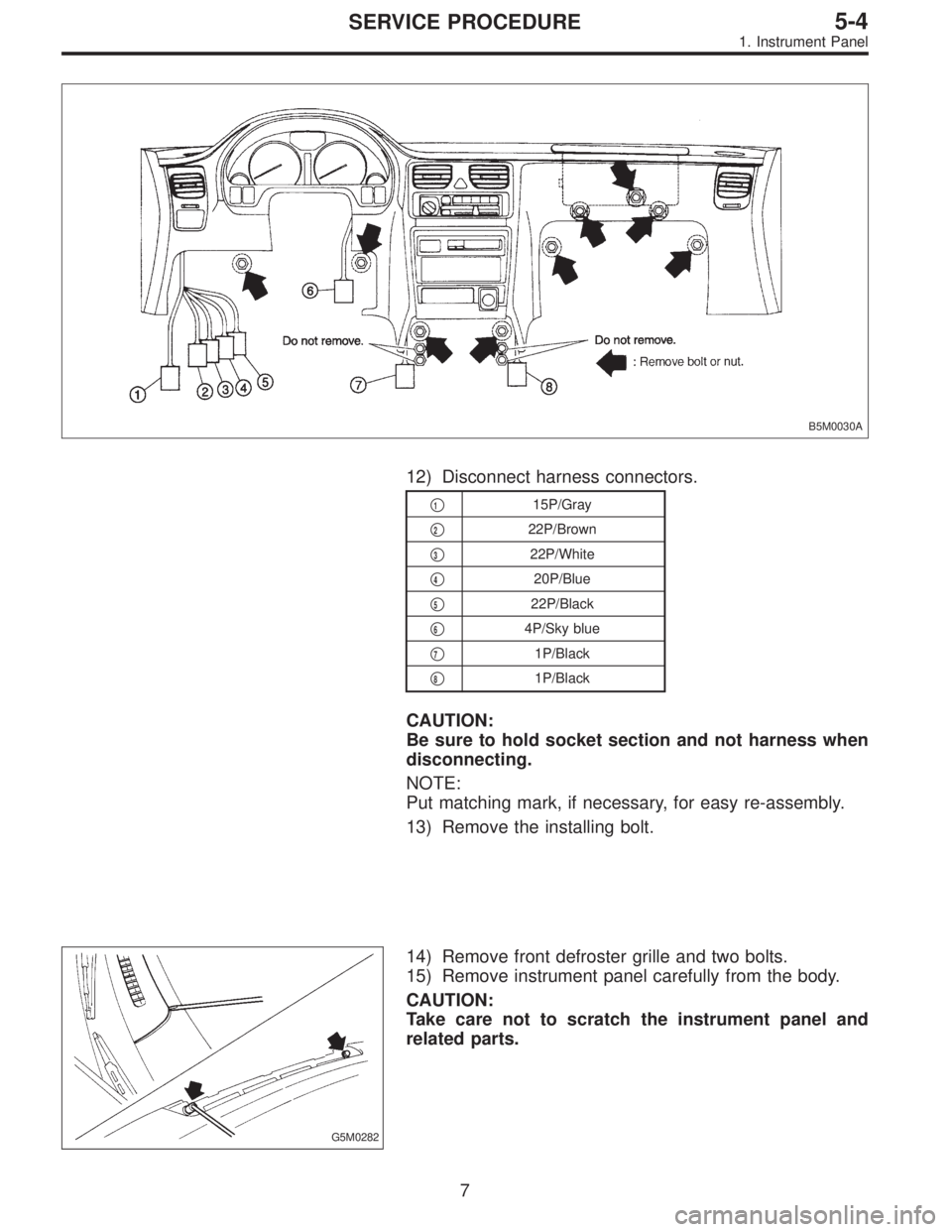
B5M0030A
12) Disconnect harness connectors.
�115P/Gray
�
222P/Brown
�
322P/White
�
420P/Blue
�
522P/Black
�
64P/Sky blue
�
71P/Black
�
81P/Black
CAUTION:
Be sure to hold socket section and not harness when
disconnecting.
NOTE:
Put matching mark, if necessary, for easy re-assembly.
13) Remove the installing bolt.
G5M0282
14) Remove front defroster grille and two bolts.
15) Remove instrument panel carefully from the body.
CAUTION:
Take care not to scratch the instrument panel and
related parts.
7
5-4SERVICE PROCEDURE
1. Instrument Panel
Page 1584 of 2890
G5M0312
3) Remove lower cover.
Disconnect airbag connector (AB3) and (AB8) below steer-
ing column.
CAUTION:
Do not reconnect airbag connector at steering column
until front sensors are securely re-installed.
G5M0313
4) Remove console box. Discon-
nect 2-pin blue connector (AB4) (right side front sensor)
and 2-pin orange connector (AB5) (left side front sensor)
from airbag control module.
G5M0314
5) Roll up floor mat and side sill cover.
[W5A10].> Remove front sensor harness from clip and pro-
tector.
6) Remove front wheels.
7) Remove front mud guard.
G5M0315
8) Remove wiring harness clips.
G5M0316
9) Remove grommet.
14
5-5SERVICE PROCEDURE
4. Front Sensor
Page 1589 of 2890
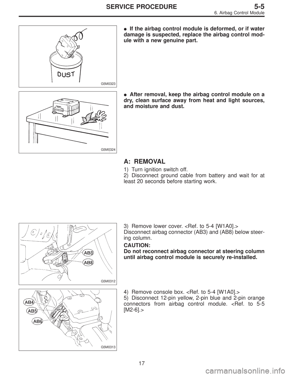
G5M0323
�If the airbag control module is deformed, or if water
damage is suspected, replace the airbag control mod-
ule with a new genuine part.
G5M0324
�After removal, keep the airbag control module on a
dry, clean surface away from heat and light sources,
and moisture and dust.
A: REMOVAL
1) Turn ignition switch off.
2) Disconnect ground cable from battery and wait for at
least 20 seconds before starting work.
G5M0312
3) Remove lower cover.
Disconnect airbag connector (AB3) and (AB8) below steer-
ing column.
CAUTION:
Do not reconnect airbag connector at steering column
until airbag control module is securely re-installed.
G5M0313
4) Remove console box.
5) Disconnect 12-pin yellow, 2-pin blue and 2-pin orange
connectors from airbag control module.
[M2-6].>
17
5-5SERVICE PROCEDURE
6. Airbag Control Module
Page 2614 of 2890
1. Electrical Components Location
B5M0395A
Connector No. (AB1) (AB2) (AB3) (AB4) (AB5) (AB6) (AB7) (AB8) (AB9) (AB10)
Pole73322123333
Color Yellow Yellow Yellow Blue Orange Yellow Yellow Yellow Yellow Yellow
Male/Female Male Female Female Female Female Female Male Male Male Female
2
5-5SUPPLEMENTAL RESTRAINT SYSTEM
1. Electrical Components Location
![SUBARU LEGACY 1996 Service Repair Manual G5M0312
3) Remove lower cover. <Ref. to 5-4 [W1A0].>
Disconnect airbag connector (AB3) and (AB8) below steer-
ing column.
CAUTION:
Do not reconnect airbag connector at steering column
until front sens](/manual-img/17/57433/w960_57433-1583.png "SUBARU LEGACY 1996 Service Repair Manual G5M0312
3) Remove lower cover. <Ref. to 5-4 [W1A0].>
Disconnect airbag connector (AB3) and (AB8) below steer-
ing column.
CAUTION:
Do not reconnect airbag connector at steering column
until front sens")
 (AB2) (AB3) (AB4) (AB5) (AB6) (AB7) (AB8) (AB9) (AB10)
Pole73322123333
Color Yellow Yellow Yellow Blue Orange Yellow Yellow Yellow Yellow")