Page 562 of 2890
G2M0345
3. Fuel Tank
A: REMOVAL
1) Release fuel pressure.
2) Drain fuel from fuel tank.
G2M0382
3) Remove rear exhaust pipe.
(1) Lift-up the vehicle.
(2) Separate rear exhaust pipe from center exhaust
pipe.
(3) Separate rear exhaust pipe from muffler.
(4) Remove bracket from rubber cushion, and remove
exhaust pipe.
NOTE:
To facilitate the removal of parts, apply a coat of SUBARU
CRC5-56 (Part No. 004301003)
G2M0384
4) Remove muffler assembly.
NOTE:
To facilitate the removal of parts, apply a coat of SUBARU
CRC5-56 (Part No. 004301003)
G3M0059
5) Remove rear differential assembly. (AWD model)
(1) Remove rear axle shafts from rear differential
assembly.
(2) Remove rear differential front cover.
(3) Remove propeller shaft.
(4) Remove lower differential bracket.
(5) Set transmission jack under rear differential.
(6) Remove bolts which install rear differential onto
rear crossmember.
13
2-8SERVICE PROCEDURE
3. Fuel Tank
Page 565 of 2890
G3M0059
6) Install rear differential assembly.
G2M0384
7) Install muffler assembly.
G2M0382
8) Install heat sealed cover.
9) Install rear exhaust pipe.
G2M0340
10) Lower the vehicle, and connect connector to fuel
pump.
11) Install access hole lid.
G2M0345
4. Fuel Filler Pipe
A: REMOVAL
1) Release fuel pressure.
2) Drain fuel from fuel tank.
16
2-8SERVICE PROCEDURE
3. Fuel Tank - 4. Fuel Filler Pipe
Page 671 of 2890
G2M0345
3. Fuel Tank
A: REMOVAL
1) Release fuel pressure.
2) Drain fuel from fuel tank.
G2M0382
3) Remove rear exhaust pipe.
(1) Lift-up the vehicle.
(2) Separate rear exhaust pipe from center exhaust
pipe.
(3) Separate rear exhaust pipe from muffler.
(4) Remove bracket from rubber cushion, and remove
exhaust pipe.
NOTE:
To facilitate the removal of parts, apply a coat of SUBARU
CRC5-56 (Part No. 004301003)
G2M0384
4) Remove muffler assembly.
NOTE:
To facilitate the removal of parts, apply a coat of SUBARU
CRC5-56 (Part No. 004301003)
G3M0059
5) Remove rear differential assembly. (AWD model)
(1) Remove rear axle shafts from rear differential
assembly.
(2) Remove rear differential front cover.
(3) Remove propeller shaft.
(4) Remove lower differential bracket.
(5) Set transmission jack under rear differential.
(6) Remove bolts which install rear differential onto
rear crossmember.
13
2-8SERVICE PROCEDURE
3. Fuel Tank
Page 674 of 2890
G3M0059
6) Install rear differential assembly.
G2M0384
7) Install muffler assembly.
G2M0382
8) Install heat sealed cover.
9) Install rear exhaust pipe.
G2M0340
10) Lower the vehicle, and connect connector to fuel
pump.
11) Install access hole lid.
G2M0345
4. Fuel Filler Pipe
A: REMOVAL
1) Release fuel pressure.
2) Drain fuel from fuel tank.
16
2-8SERVICE PROCEDURE
3. Fuel Tank - 4. Fuel Filler Pipe
Page 675 of 2890
G3M0059
6) Install rear differential assembly.
G2M0384
7) Install muffler assembly.
G2M0382
8) Install heat sealed cover.
9) Install rear exhaust pipe.
G2M0340
10) Lower the vehicle, and connect connector to fuel
pump.
11) Install access hole lid.
G2M0345
4. Fuel Filler Pipe
A: REMOVAL
1) Release fuel pressure.
2) Drain fuel from fuel tank.
16
2-8SERVICE PROCEDURE
3. Fuel Tank - 4. Fuel Filler Pipe
Page 746 of 2890
G2M0316
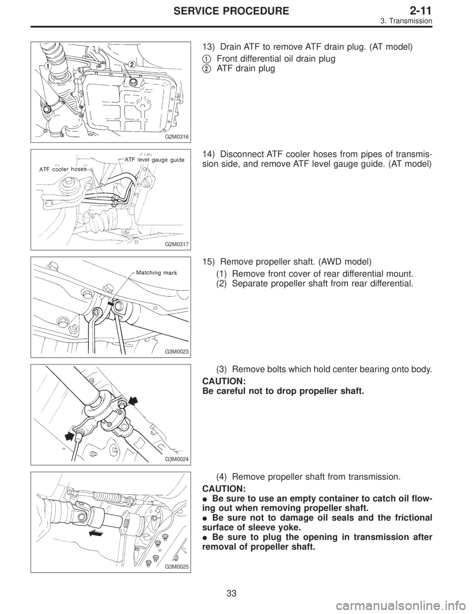
13) Drain ATF to remove ATF drain plug. (AT model)
�
1Front differential oil drain plug
�
2ATF drain plug
G2M0317
14) Disconnect ATF cooler hoses from pipes of transmis-
sion side, and remove ATF level gauge guide. (AT model)
G3M0023
15) Remove propeller shaft. (AWD model)
(1) Remove front cover of rear differential mount.
(2) Separate propeller shaft from rear differential.
G3M0024
(3) Remove bolts which hold center bearing onto body.
CAUTION:
Be careful not to drop propeller shaft.
G3M0025
(4) Remove propeller shaft from transmission.
CAUTION:
�Be sure to use an empty container to catch oil flow-
ing out when removing propeller shaft.
�Be sure not to damage oil seals and the frictional
surface of sleeve yoke.
�Be sure to plug the opening in transmission after
removal of propeller shaft.
33
2-11SERVICE PROCEDURE
3. Transmission
Page 754 of 2890
G2M0317
13) Install ATF level gauge guide, and ATF cooler hoses
onto pipe. (AT model)
G3M0023
14) Install propeller shaft. (AWD model)
(1) Install propeller shaft into transmission.
(2) Tighten bolts which install propeller shaft onto com-
panion flange of rear differential.
Tightening torque:
31±8 N⋅m (3.2±0.8 kg-m, 23.1±5.8 ft-lb)
G3M0024
(3) Install center bearing bracket on body.
Tightening torque:
52±5 N⋅m (5.3±0.5 kg-m, 38.3±3.6 ft-lb)
G2M0830
15) Install exhaust system.
(1) Install heat shield cover. (AWD model)
G2M0382
(2) Install rear exhaust pipe to muffler. (AWD model)
Tightening torque:
48±9 N⋅m (4.9±0.9 kg-m, 35.4±6.5 ft-lb)
41
2-11SERVICE PROCEDURE
3. Transmission
Page 758 of 2890
1. Manual Transmission and
Differential
A: SPECIFICATIONS
ItemModel
FWD AWD
2200 cc 2200 cc*2200 cc
OUTBACK
Type 5-forward speeds with synchromesh and 1-reverse
Transmission gear ratio1st 3.545
2nd 2.111
3rd 1.448
4th 1.088
5th 0.825 0.780 0.871
Reverse 3.416
Front
reduction
gearFinalType of gear Hypoid
Gear ratio 3.454 3.900 4.111
Rear
reduction
gearTransferType of gear — Helical
Gear ratio — 1.000
FinalType of gear — Hypoid
Gear ratio — 3.900 4.111
Front
differentialType and number of gear Straight bevel gear (Bevel pinion: 2, Bevel gear: 2)
Center
differentialType and number of gear —Straight bevel gear
(Bevel pinion: 2, Bevel gear: 2 and viscous coupling)
Transmission gear oil GL-5
Transmission oil capacity3.3�(3.5 US qt, 2.9 Imp
qt)3.5�(3.7 US qt, 3.1 Imp qt)
*: Step roof model only
2
3-1SPECIFICATIONS AND SERVICE DATA
1. Manual Transmission and Differential
![SUBARU LEGACY 1996 Service Repair Manual G2M0345
3. Fuel Tank
A: REMOVAL
1) Release fuel pressure. <Ref. to 2-8 [W1A0].>
2) Drain fuel from fuel tank. <Ref. to 2-8 [W1B0].>
G2M0382
3) Remove rear exhaust pipe.
(1) Lift-up the vehicle.
(2) Se](/manual-img/17/57433/w960_57433-561.png "SUBARU LEGACY 1996 Service Repair Manual G2M0345
3. Fuel Tank
A: REMOVAL
1) Release fuel pressure. <Ref. to 2-8 [W1A0].>
2) Drain fuel from fuel tank. <Ref. to 2-8 [W1B0].>
G2M0382
3) Remove rear exhaust pipe.
(1) Lift-up the vehicle.
(2) Se")
![SUBARU LEGACY 1996 Service Repair Manual G3M0059
6) Install rear differential assembly. <Ref. to 3-4 [W2F0].>
G2M0384
7) Install muffler assembly.
G2M0382
8) Install heat sealed cover.
9) Install rear exhaust pipe.
G2M0340
10) Lower the vehi](/manual-img/17/57433/w960_57433-564.png "SUBARU LEGACY 1996 Service Repair Manual G3M0059
6) Install rear differential assembly. <Ref. to 3-4 [W2F0].>
G2M0384
7) Install muffler assembly.
G2M0382
8) Install heat sealed cover.
9) Install rear exhaust pipe.
G2M0340
10) Lower the vehi")
![SUBARU LEGACY 1996 Service Repair Manual G2M0345
3. Fuel Tank
A: REMOVAL
1) Release fuel pressure. <Ref. to 2-8 [W1A0].>
2) Drain fuel from fuel tank. <Ref. to 2-8 [W1B0].>
G2M0382
3) Remove rear exhaust pipe.
(1) Lift-up the vehicle.
(2) Se](/manual-img/17/57433/w960_57433-670.png "SUBARU LEGACY 1996 Service Repair Manual G2M0345
3. Fuel Tank
A: REMOVAL
1) Release fuel pressure. <Ref. to 2-8 [W1A0].>
2) Drain fuel from fuel tank. <Ref. to 2-8 [W1B0].>
G2M0382
3) Remove rear exhaust pipe.
(1) Lift-up the vehicle.
(2) Se")
![SUBARU LEGACY 1996 Service Repair Manual G3M0059
6) Install rear differential assembly. <Ref. to 3-4 [W2F0].>
G2M0384
7) Install muffler assembly.
G2M0382
8) Install heat sealed cover.
9) Install rear exhaust pipe.
G2M0340
10) Lower the vehi](/manual-img/17/57433/w960_57433-673.png "SUBARU LEGACY 1996 Service Repair Manual G3M0059
6) Install rear differential assembly. <Ref. to 3-4 [W2F0].>
G2M0384
7) Install muffler assembly.
G2M0382
8) Install heat sealed cover.
9) Install rear exhaust pipe.
G2M0340
10) Lower the vehi")
![SUBARU LEGACY 1996 Service Repair Manual G3M0059
6) Install rear differential assembly. <Ref. to 3-4 [W2F0].>
G2M0384
7) Install muffler assembly.
G2M0382
8) Install heat sealed cover.
9) Install rear exhaust pipe.
G2M0340
10) Lower the vehi](/manual-img/17/57433/w960_57433-674.png "SUBARU LEGACY 1996 Service Repair Manual G3M0059
6) Install rear differential assembly. <Ref. to 3-4 [W2F0].>
G2M0384
7) Install muffler assembly.
G2M0382
8) Install heat sealed cover.
9) Install rear exhaust pipe.
G2M0340
10) Lower the vehi")
 Install ATF level gauge guide, and ATF cooler hoses
onto pipe. (AT model)
G3M0023
14) Install propeller shaft. (AWD model)
(1) Install propeller shaft into transmission.
(2) Tighten bolts")
