Page 1375 of 2890

1. Air Conditioning System
A: SPECIFICATIONS
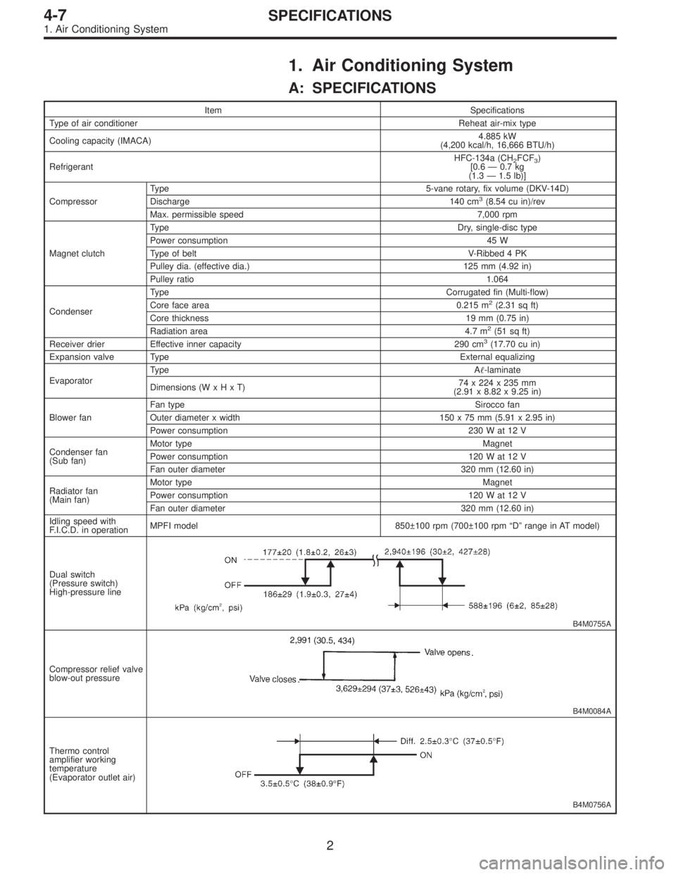
Item Specifications
Type of air conditionerReheat air-mix type
Cooling capacity (IMACA)4.885 kW
(4,200 kcal/h, 16,666 BTU/h)
RefrigerantHFC-134a (CH
2FCF3)
[0.6 — 0.7 kg
(1.3 — 1.5 lb)]
CompressorType 5-vane rotary, fix volume (DKV-14D)
Discharge 140 cm
3(8.54 cu in)/rev
Max. permissible speed 7,000 rpm
Magnet clutchTy p eDry, single-disc type
Power consumption 45 W
Type of belt V-Ribbed 4 PK
Pulley dia. (effective dia.) 125 mm (4.92 in)
Pulley ratio1.064
CondenserType Corrugated fin (Multi-flow)
Core face area 0.215 m
2(2.31 sq ft)
Core thickness 19 mm (0.75 in)
Radiation area 4.7 m
2(51 sq ft)
Receiver drier Effective inner capacity 290 cm3(17.70 cu in)
Expansion valve TypeExternal equalizing
EvaporatorTy p eA�-laminate
Dimensions (W x H x T)74 x 224 x 235 mm
(2.91 x 8.82 x 9.25 in)
Blower fanFan typeSirocco fan
Outer diameter x width 150 x 75 mm (5.91 x 2.95 in)
Power consumption 230 W at 12 V
Condenser fan
(Sub fan)Motor typeMagnet
Power consumption 120 W at 12 V
Fan outer diameter 320 mm (12.60 in)
Radiator fan
(Main fan)Motor typeMagnet
Power consumption 120 W at 12 V
Fan outer diameter 320 mm (12.60 in)
Idling speed with
F.I.C.D. in operationMPFI model 850±100 rpm (700±100 rpm “D” range in AT model)
Dual switch
(Pressure switch)
High-pressure line
B4M0755A
Compressor relief valve
blow-out pressure
B4M0084A
Thermo control
amplifier working
temperature
(Evaporator outlet air)
B4M0756A
2
4-7SPECIFICATIONS
1. Air Conditioning System
Page 1382 of 2890

1. Safety Precautions
1. HFC-134a AIR CONDITIONING SYSTEM
Component parts of the cooling system, refrigerant, com-
pressor oil, and other parts are not the same for the HFC-
134a system and the older CFC-12 system. Do not inter-
change parts or liquid.
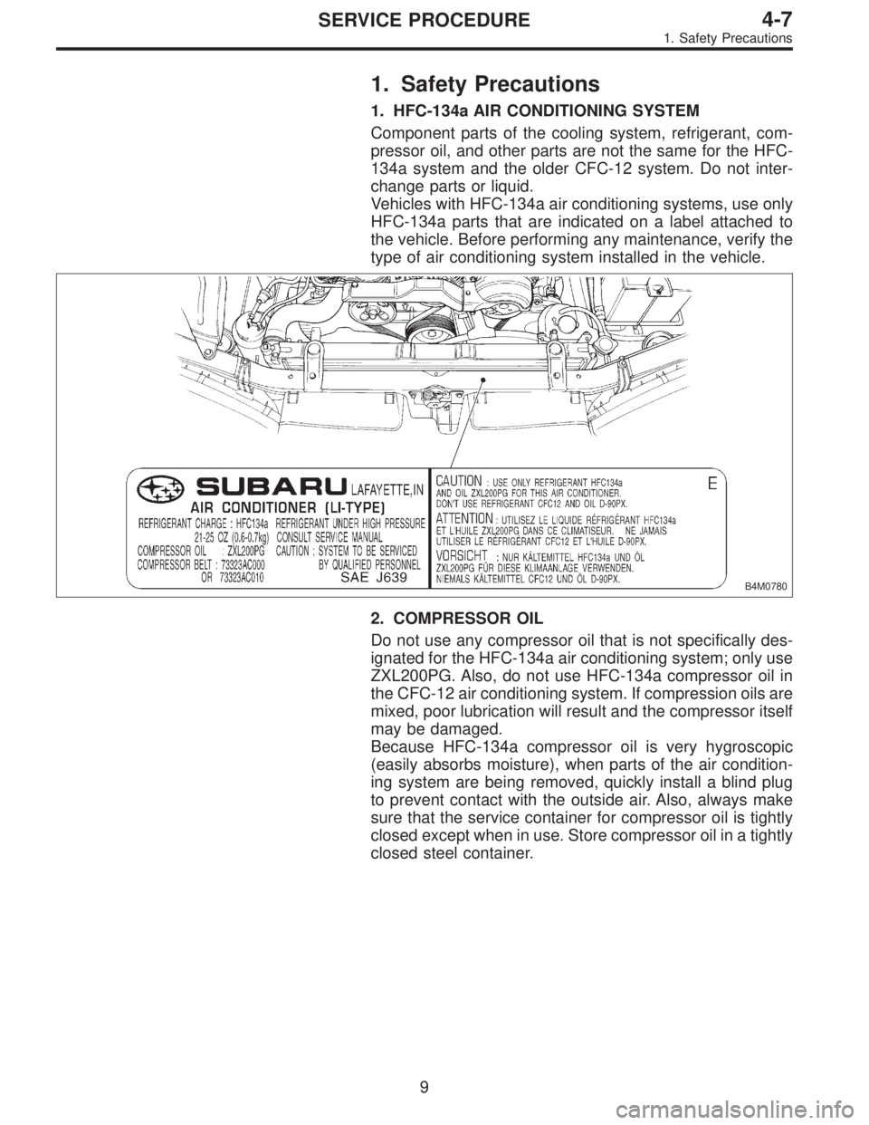
Vehicles with HFC-134a air conditioning systems, use only
HFC-134a parts that are indicated on a label attached to
the vehicle. Before performing any maintenance, verify the
type of air conditioning system installed in the vehicle.
B4M0780
2. COMPRESSOR OIL
Do not use any compressor oil that is not specifically des-
ignated for the HFC-134a air conditioning system; only use
ZXL200PG. Also, do not use HFC-134a compressor oil in
the CFC-12 air conditioning system. If compression oils are
mixed, poor lubrication will result and the compressor itself
may be damaged.
Because HFC-134a compressor oil is very hygroscopic
(easily absorbs moisture), when parts of the air condition-
ing system are being removed, quickly install a blind plug
to prevent contact with the outside air. Also, always make
sure that the service container for compressor oil is tightly
closed except when in use. Store compressor oil in a tightly
closed steel container.
9
4-7SERVICE PROCEDURE
1. Safety Precautions
Page 1385 of 2890

3. Tools and Equipment
The following section provides information about the tools
and equipment that will be necessary to properly service
the A/C system.
Since equipment may vary slightly depending on the
manufacturer, it is important to always read and follow the
manufacturer’s instructions.
CAUTION:
When working on vehicles with the HFC-134a system,
only use HFC-134a specified tools and parts. Do not
mix with CFC-12 tools and parts. If HFC-134a and
CFC-12 refrigerant or compressor oil is mixed, poor
lubrication will result and the compressor itself may be
destroyed.
In order to help prevent mixing HFC-134a and CFC-12
parts and liquid, the tool and screw type and the type
of service valves used are different. The gas leak
detectors for the HFC-134a and CFC-12 systems must
also not be interchanged.
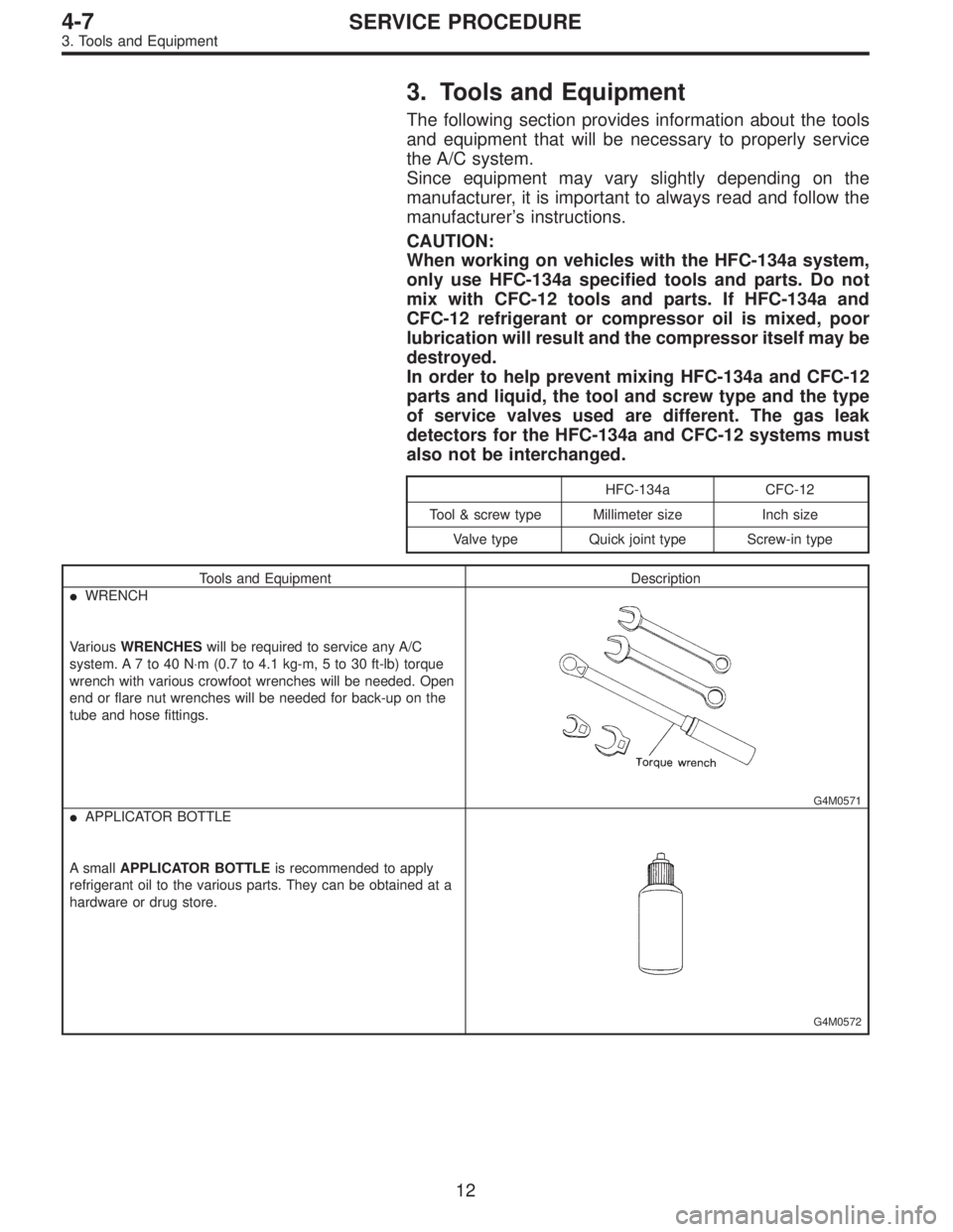
HFC-134a CFC-12
Tool & screw type Millimeter size Inch size
Valve type Quick joint type Screw-in type
Tools and Equipment Description
�WRENCH
VariousWRENCHESwill be required to service any A/C
system. A 7 to 40 N⋅m (0.7 to 4.1 kg-m, 5 to 30 ft-lb) torque
wrench with various crowfoot wrenches will be needed. Open
end or flare nut wrenches will be needed for back-up on the
tube and hose fittings.
G4M0571
�APPLICATOR BOTTLE
A smallAPPLICATOR BOTTLEis recommended to apply
refrigerant oil to the various parts. They can be obtained at a
hardware or drug store.
G4M0572
12
4-7SERVICE PROCEDURE
3. Tools and Equipment
Page 1396 of 2890

8. Leak Testing
The following points should be kept in mind when conduct-
ing a refrigerant leak test.
1) The A/C system to be tested must have an adequate
refrigerant charge to begin with.
2) The area where the leak test is conducted must be free
of wind and drafts, with still air being the ideal condition.
3) The atmosphere where the leak test is conducted must
be free of refrigerant contamination.
4) Operate the A/C system for approx. 10 minutes, then
turn the engine off an begin the leak test.
5) Refrigerant gas is heavier than air, therefore always
hold the probe below the connection being tested.
6) When checking for a leak along a length of hose or
tube, the leak detector probe must be moved slowly,
approx. 25 mm (1 in) per second making sure probe does
not come in contact with the component being tested.
7) When checking for a leak at a certain point, the leak
detector probe must be held at that point for at least 5
seconds.
G4M0609
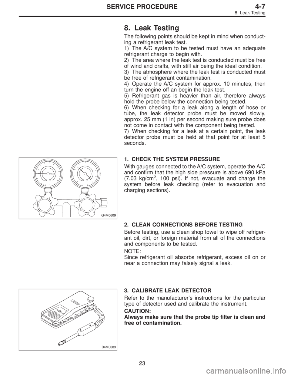
1. CHECK THE SYSTEM PRESSURE
With gauges connected to the A/C system, operate the A/C
and confirm that the high side pressure is above 690 kPa
(7.03 kg/cm
2, 100 psi). If not, evacuate and charge the
system before leak checking (refer to evacuation and
charging sections).
2. CLEAN CONNECTIONS BEFORE TESTING
Before testing, use a clean shop towel to wipe off refriger-
ant oil, dirt, or foreign material from all of the connections
and components to be tested.
NOTE:
Since refrigerant oil absorbs refrigerant, excess oil on or
near a connection may falsely signal a leak.
B4M0089
3. CALIBRATE LEAK DETECTOR
Refer to the manufacturer’s instructions for the particular
type of detector used and calibrate the instrument.
CAUTION:
Always make sure that the probe tip filter is clean and
free of contamination.
23
4-7SERVICE PROCEDURE
8. Leak Testing