Page 173 of 2890
![SUBARU LEGACY 1996 Service Repair Manual 6-3
[D601]
WIRING
DIAGRAM
6
.
Wiring
Diagram
6
.
Wiring
Diagram
Batterycurrent
1
.
POWER
SUPPLY
ROUTING
Current
fromignition
switch
IG
terminal
---
Current
fromignition
switch
ACC
terminal
-----](/manual-img/17/57433/w960_57433-172.png "SUBARU LEGACY 1996 Service Repair Manual 6-3
[D601]
WIRING
DIAGRAM
6
.
Wiring
Diagram
6
.
Wiring
Diagram
Batterycurrent
1
.
POWER
SUPPLY
ROUTING
Current
fromignition
switch
IG
terminal
---
Current
fromignition
switch
ACC
terminal
-----")
6-3
[D601]
WIRING
DIAGRAM
6
.
Wiring
Diagram
6
.
Wiring
Diagram
Batterycurrent
1
.
POWER
SUPPLY
ROUTING
Current
fromignition
switch
IG
terminal
---
Current
fromignition
switch
ACC
terminal
-------
Other
currents
Mainfuse
box
(M/B)
g27
SBF-5
45A
~
L
SBF-4
45A
,
BY
r-,
coc_
:
/CA
1
Do
BF-1
30A
BF-2
30A
N
m
m
M/B
FUSE/RELAY
LOCATION
826
-
MB-1
2
Rw
M
B-2
1
MB-3
R
-
MB-4
(
:8
~V
:
9)
,
R
F35
Headlight
No
.
22
15A
5
W
relay
LHNo
.
23
20A
Br
6
°
No
.
24
15A
RL
-----
---------
------0'
~-P--
1
---------°^----
MB-6
7
LB
7
No
.
26
15A
BY
°
~
~
_
No
.
25
15A
3
--°--°
BR
MB-8
.J
4
LR
2
MB-9
Headlight
relay
RH
F38
r~W
WC
relay
holder
mmllmm
O
~
SBFSBF
~~~
~
Head
i~25
N0
'
24
Headlight
4A
No,
relay
RH
~
SBF
~
38fSBf
N0
.
b
F/B
a
N0
.
--
2
:
0
N0
.f
o
N
.
176
N
RU7
.
R-DEF
N0
.
7
N0
.
N
.
3
0N
.
It
.4
~~
P
I
.7
LEI]
o
O
N0
.
19N0
.
12N0
.
~y~~~,~~~
ILLUrtI
.
O
N0.21
N0
.
14
N0
.7
MAIN
FAN
,
D
2
IF--
F26
F38
(B
I
ec
k)
2
B27
123
--'----
ALT-1
B26
(B
I
ac
k)
F26
(Grey)
12
F35
(B
I
ec
k)
1234
5678
BURO1-01A
Page 968 of 2890
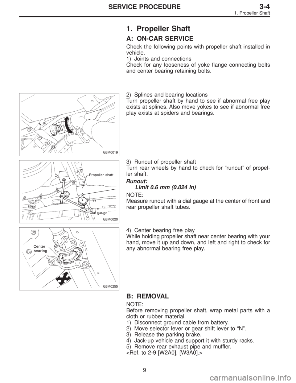
1. Propeller Shaft
A: ON-CAR SERVICE
Check the following points with propeller shaft installed in
vehicle.
1) Joints and connections
Check for any looseness of yoke flange connecting bolts
and center bearing retaining bolts.
G3M0019
2) Splines and bearing locations
Turn propeller shaft by hand to see if abnormal free play
exists at splines. Also move yokes to see if abnormal free
play exists at spiders and bearings.
G3M0020
3) Runout of propeller shaft
Turn rear wheels by hand to check for“runout”of propel-
ler shaft.
Runout:
Limit 0.6 mm (0.024 in)
NOTE:
Measure runout with a dial gauge at the center of front and
rear propeller shaft tubes.
G3M0255
4) Center bearing free play
While holding propeller shaft near center bearing with your
hand, move it up and down, and left and right to check for
any abnormal bearing free play.
B: REMOVAL
NOTE:
Before removing propeller shaft, wrap metal parts with a
cloth or rubber material.
1) Disconnect ground cable from battery.
2) Move selector lever or gear shift lever to“N”.
3) Release the parking brake.
4) Jack-up vehicle and support it with sturdy racks.
5) Remove rear exhaust pipe and muffler.
9
3-4SERVICE PROCEDURE
1. Propeller Shaft
Page 1415 of 2890
![SUBARU LEGACY 1996 Service Repair Manual B4M0103
B4M0764
16. Flexible Hose
A: REMOVAL AND INSTALLATION
1) Disconnect battery negative terminal.
2) Discharge refrigerant using refrigerant recovery system.
<Ref. to 4-7 [W601].>
3) Remove low-p](/manual-img/17/57433/w960_57433-1414.png "SUBARU LEGACY 1996 Service Repair Manual B4M0103
B4M0764
16. Flexible Hose
A: REMOVAL AND INSTALLATION
1) Disconnect battery negative terminal.
2) Discharge refrigerant using refrigerant recovery system.
<Ref. to 4-7 [W601].>
3) Remove low-p")
B4M0103
B4M0764
16. Flexible Hose
A: REMOVAL AND INSTALLATION
1) Disconnect battery negative terminal.
2) Discharge refrigerant using refrigerant recovery system.
3) Remove low-pressure hose.
(1) Remove hose attaching bolts.
CAUTION:
Plug the opening to prevent foreign matter from get-
ting in.
(2) Disconnect the connector at evaporator module.
4) Remove high-pressure hose.
(1) Disconnect hose attaching bolt (compressor side).
(2) Disconnect hose attaching bolt (condenser side).
CAUTION:
Plug the opening to prevent foreign matter from get-
ting in.
5) Installation is in the reverse order of removal.
6) Charge refrigerant.
G4M0649
17. Relay and Fuse
A: LOCATION
Relays used with A/C system are located as shown in fig-
ure.
1) A/C relay
2) Main fan (radiator fan) relay
3) Sub fan (condenser fan) relay
4) Sub fan (condenser fan) water temperature relay
5) Fuses (10 A and 20 A)
G4M0651
B: INSPECTION
1) Check conduction with a circuit tester (ohm range)
according to the following table in figure.
B4M0105A
2) Replace relays which do not meet specifications.
39
4-7SERVICE PROCEDURE
16. Flexible Hose - 17. Relay and Fuse
Page 1416 of 2890
![SUBARU LEGACY 1996 Service Repair Manual B4M0103
B4M0764
16. Flexible Hose
A: REMOVAL AND INSTALLATION
1) Disconnect battery negative terminal.
2) Discharge refrigerant using refrigerant recovery system.
<Ref. to 4-7 [W601].>
3) Remove low-p](/manual-img/17/57433/w960_57433-1415.png "SUBARU LEGACY 1996 Service Repair Manual B4M0103
B4M0764
16. Flexible Hose
A: REMOVAL AND INSTALLATION
1) Disconnect battery negative terminal.
2) Discharge refrigerant using refrigerant recovery system.
<Ref. to 4-7 [W601].>
3) Remove low-p")
B4M0103
B4M0764
16. Flexible Hose
A: REMOVAL AND INSTALLATION
1) Disconnect battery negative terminal.
2) Discharge refrigerant using refrigerant recovery system.
3) Remove low-pressure hose.
(1) Remove hose attaching bolts.
CAUTION:
Plug the opening to prevent foreign matter from get-
ting in.
(2) Disconnect the connector at evaporator module.
4) Remove high-pressure hose.
(1) Disconnect hose attaching bolt (compressor side).
(2) Disconnect hose attaching bolt (condenser side).
CAUTION:
Plug the opening to prevent foreign matter from get-
ting in.
5) Installation is in the reverse order of removal.
6) Charge refrigerant.
G4M0649
17. Relay and Fuse
A: LOCATION
Relays used with A/C system are located as shown in fig-
ure.
1) A/C relay
2) Main fan (radiator fan) relay
3) Sub fan (condenser fan) relay
4) Sub fan (condenser fan) water temperature relay
5) Fuses (10 A and 20 A)
G4M0651
B: INSPECTION
1) Check conduction with a circuit tester (ohm range)
according to the following table in figure.
B4M0105A
2) Replace relays which do not meet specifications.
39
4-7SERVICE PROCEDURE
16. Flexible Hose - 17. Relay and Fuse
Page 2738 of 2890
2. Basic Diagnostics Procedures
The most important purpose of diagnostics is to determine
which part is malfunctioning quickly, to save time and labor.
A: IDENTIFICATION OF TROUBLE SYMPTOM
Determine what the problem is based on the symptom.
B: PROBABLE CAUSE OF TROUBLE
Look at the wiring diagram and check the system’s circuit.
Then check the switch, relay, fuse, ground, etc.
C: LOCATION AND REPAIR OF TROUBLE
1) Using the diagnostics narrow down the causes.
2) If necessary, use a voltmeter, ohmmeter, etc.
3) Before replacing certain component parts (switch, relay,
etc.), check the power supply, ground, for open wiring
harness, poor connectors, etc. If no problems are
encountered, check the component parts.
D: CONFIRMATION OF SYSTEM OPERATION
After repairing, ensure that the system operates properly.
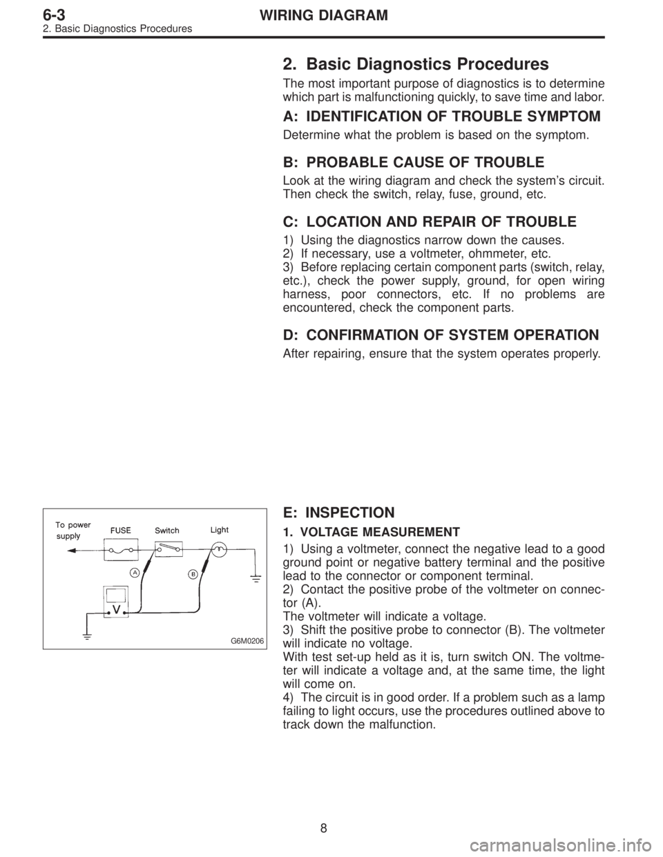
G6M0206
E: INSPECTION
1. VOLTAGE MEASUREMENT
1) Using a voltmeter, connect the negative lead to a good
ground point or negative battery terminal and the positive
lead to the connector or component terminal.
2) Contact the positive probe of the voltmeter on connec-
tor (A).
The voltmeter will indicate a voltage.
3) Shift the positive probe to connector (B). The voltmeter
will indicate no voltage.
With test set-up held as it is, turn switch ON. The voltme-
ter will indicate a voltage and, at the same time, the light
will come on.
4) The circuit is in good order. If a problem such as a lamp
failing to light occurs, use the procedures outlined above to
track down the malfunction.
8
6-3WIRING DIAGRAM
2. Basic Diagnostics Procedures